heavy cast iron brackets I in Fig. 1, each'. 12"&(12". .... beams is plane polarized at the initial angle 0 at ... angles to the fiber axis, nor can the light be projected ...
JULY 15, i936
PH
YSI CAL REVIEW
Mechanical Detection and Measurement RIcHARD A. BETH,
voLUM E 50
of the Angular Momentum
of Light
Worcester Polytechnic Institlte, Worcester, Mass. and Palmer Physical Laboratory, Princeton
University
(Received May 8, 1936)
The electromagnetic theory of the torque exerted by a beam of polarized light on a doubly refracting plate which alters its state of polarization is summarized. The same quantitative result is obtained by assigning an angular momentum of )I'i ( — k) to each quantum of left (right) circularly polarized light in a vacuum, and assuming the conservation of angular momentum holds at the face of the plate. The apparatus used to detect and measure this effect
ELEcTRQMAGNETIc
FIELD THEoRY
HE moment of force or torque exerted on a doubly refracting medium by a light wave passing through it arises from the fact that the dielectric constant K is a tensor. Consequently the electric intensity E is, in general, not parallel to the electric polarization P or to the electric displacement
D = KE = E+4+P
The torque per unit volume produced by the action of the electric held on the polarization of the medium is in the medium.
1=PXE= (DXE)/4~. Following Sadowsky and Epstein' we may calculate this torque for a simple case as follows: Assume a doubly refracting medium of permeability unity and take as x, y, and s axes the principal axes of the tensor K for the light frequency in question. Denote the principal values of K by n, ', ri„'and nP so that n, n„and n, will be the principal indices of refraction. Let the electric components of a plane light wave * Member
was designed to enhance the moment of force to be measured by an appropriate arrangement of quartz wave plates, and to reduce interferences. The results of about 120 determinations by two observers working independently show the magnitude and sign of the effect to be correct, and show that it varies as predicted by the theory with each of three experimental variables which could be independently adj usted. -
propagated
+s direction
be given by
E=A cos 8 cos (Zy+6),
A sin 0 cos (Z~ — 6),
D=KE=n, 'A
0,
(Zr+6), n„'A sin 0 cos (Z~ —6), 0, (2)
cos 0 cos
=— (n„+n,)/2, . = 2 ~c/X; /— s(n, n, ) X; value of s (in particular s=0)
where Z&
~(t
ns/c);
n
cv
For any for which the wave plate thickness 6/m is a whole number the light is plane polarized and Z makes an angle +0 with the x axis. The torque per unit volume at any point in the crystal is calculated from (2) according to (1) 1=0, 0,
(A'/8~)(n,
' —I„')sin
28 cos
(Z~+6) cos
(Z~
—5)
and the time average value of the s component is
(A/4m)'(e,
' n') s— in 20 cos 2A.
Integrating from s& to s2 we get the torque per unit area on the crystal between these values:
L = —(A/47r)'nX sin 20(sin 262 —sin
of the
Worcester Physics Department, Polytechnic Institute. Preliminary work and final calculations were carried on at Worcester. Experimental work was done on leave-of-absence from Worcester as Research Associate at Palmer Physical Laboratory, Princeton University. Additional measurements were made by Mr. W. Harris at Princeton, as will be explained later. ' Sadowsky, Acta et Commentationes Imp. Uni, A. versitatis Jurievensis /, No. 1—3 (1899); 8, No. 1—2 (1900). P. S. Epstein, Ann. d. Physik 44, 593 (1914). The derivation is repeated here because the first articles are in Russian and relatively inaccessible, while in the last there seems to be a misprint in the result. I wish to thank Dr. Boris Podolsky for translating parts of Sadowsky's articles for me from the Russian. I am also deeply indebted to Professor A, Einstein not only for his advice in checking Professor Epstein's calculation but also for several interesting discussions about the experimental part of the work here reported.
in the
2A&).
(3)'
This torque, which has hitherto been generally considered too small for experimental detection, was detected and measured in the present experiment. '
' J. H. Poynting, Proc. Roy. Soc. A82, 560 (1909), infers from an ingenious mechanical analogy that circularly polarized light should exert a torque equal to the light energy per unit volume times X/2' on unit area of a quarter-wave plate which makes the light plane polarized. This result, which neglects surface reflections, is contained
(3}. R. A. Beth, Phys. Rev. 48, 471 (1935); also Annual Meeting of the Am. Phys. Soc., St. Louis, Missouri, January 1, 1936. A. H. S. Holbourn, Nature 13'7, 31 (1936), in
3
also reports successful measurement
of the effect.
ii6
RICHARD QUANTUM
THEORY
It is worth observing that (3) may be derived from the quantum theory by assigning an angular momentum or spin of Ii( fi)4 t— o each photon of left (right) circularly polarized light, the spin axis being in the direction of propagation of the light. ' Consider an elliptically polarized light wave, propagated in the +s direction in a vacuum, whose components in the directions of the principal axes of the ellipse (phase difference= ir/2) have amplitudes Xo and I'0. Let the components of the same wave, when resolved along an arbitrary pair of perpendicular x and y axes in the plane of the ellipse, be given by
E=X cos (Z+6),
Ycos (Z —6), 0,
(4)
nd 2A is the phase angle by where Z= co(t z/c) a— which the y component lags behind the x component of the wave. It may be shown that'
XYsin 25=XOYO,
X'+ Y'=Xo'+ Yo'.
(5)
If we now regard the wave (4) as the superposition of left and right circularly polarized components of amplitudes L and R, respectively, calculation shows that
L' R'=XY sin—2A
L'+R'= (X'+ Y')/2.
The number of left circularly polarized photons transmitted per unit area per second is the Poynting energy flow cL'/47r divided by the energy per photon 27rfiv=2irfic/'A, or XL'/Sir%. Multiplying by 5 gives XL2/8ir2, the angular momentum transmitted per unit area per second by the left circularly polarized component. Taking account of the similar expression for the right circularly polarized component, the angular momentum transmitted per unit area per second by the wave (4) is DE= X(L' — R')/8m'= XX Y sin 2A/Sir'
= XXn Yo/8x'
It
is well known
(6)
that the linear momentum
A =h/27r. 'A. E. Ruark and H. C. Urey, Proc. Nat. Acad. Sci. 13, 763 (1927); Harnwell and Livingood, Experimental Atomic Physics (1933), p. 81; Brillouin, les Stctistiques Qucntigues, Chap. III (1930). 'See, e, g. , Schuster and Nicholson, Theory of Optics, third edition, pp. 14, 15 (1924), especially Eqs. (15) and
A. BETH transmitted per unit area per second energy How divided by c, in this case:
is the
(L'+R')/4' = (X'+ Y')/8n. = (Xo'+ Yo')/8ir. Thus the angular and linear momenta are proportional to the natural invariants (5) of the wave (4). For Xo —Yo their ratio is Ii=X/2ir, which is another form of Poynting's result. ' The value (6) of the angular momentum, which is independent of the quantum constant k, can be derived from the linear momentum (Poynting vector divided by c) in a finite beam, but the elementary method given is more descriptive in bringing out the fact that the quantum theory leads to the same value (3) as the wave theory for the torque on a section of a crystal. To show this equivalence we have now to obtain the angular momentum for a wave (2) in the crystal from the expression (6) for a wave in a vacuum, by placing the face of the crystal at z=zi (vacuum for z(z&) and using the conservation of angular momentum and Fresnel's expressions for the amplitudes of the, reHected and transmitted waves. In the reHected wave the y component of amplitude Y(n„1)/(n— „+&) of amplitq. de lags behind the x component X(n 1)/(n—+1) by the phase angle 2A. We get the angular momentum transmitted through the face z=zi by calculating (6) for the direct and reflected waves in the vacuum (taking account of direction of transmission of each) and assuming the conservation of angular momentum at the face
M, = X Y(ii, +nv) X sin 2A/4''(n,
+1)(nv+1)
Using Fresnel's expressions for the amplitudes, we identify the transmitted wave in the crystal with (2) at z=zi by choosing
+ 1); A sin 0 = 2 Y/(n v+1); ~=a, =~z, (n„— n, )/l .
A cos 0 = 2X/(n,
Hence the angular (2) at z = zi is
momentum
3Ei —(A/4ir)'n)
transmitted
sin 28 sin 2hi.
by
(7)
4
(17).
It can now be seen directly that the torque (3) is equal to the excess of the angular momentum (7) per unit area per second flowing into a section of the crystal at s=s& over that flowing out at s = z2. Hence both the field and the
ANGULAR
MOMENTUM
OF LIGHT
117
IN
4 J~
TO
7. ~
7 VRPJ. ~
XXXXM.MM. 4 /rr rrsy~p
M. M. XXXXX l&IV X l
P~ I'AVAXV
lhiiiiiii
f
of apparatus.
P~
bXNW 'AX'AV:A V. iiMXA Yi'DAl/p
I
)
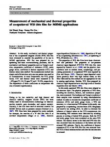
FIG. 2. Photograph
f
I
,I
l
I I
I I
stray heating effects, radiometer and gas effects, and variations in light pressure, the apparatus was constructed as shown in Figs. 1, 2, 3, and 4. Some of the precautions taken to avoid these interferences may have been unnecessary, but they were sufficient. The whole apparatus is supported on the heavy cast iron brackets I in Fig. 1, each' 12"&(12"., which are bolted to a brick pier to avoid mechanical disturbances, especially torsional vibrations of a period comparable to that
II \
/
FIG. 1. Diagram of apparatus.
quantum theories predict the same value for the effect which has been measured in the present experiment. APPARATUS
The basic idea used in detecting and measuring the effect~ is to observe the deflection of a quartz wave plate hung from a fine quartz fiber when suitably polarized light is sent through the plate. In order to increase the effect to be measured and to avoid as far as possible interfering effects due to mechanical and electrostatic disturbances,
~(LOW
M
L I
O
„I ~ See Poynting, reference 2, A. Kastler, Societe des Sciences physiques et naturelles de Bordeaux, Jan. 28, 1932. R, A. Beth, abstract, Boston Meeting, American Physical Society, Phys. Rev. 45, 296 (1934).
I I I I
PI. AHE, OF EI-KCTRIC VECTOR
L
OF llCIIT FAOHI NICOI-
FIG. 3. Wave plate arrangement.
RI CHARD -'jI'
":gpss
A. BETH measurements which might be ascribed to radiometer or gas effects. Light from a three-millimeter tungsten ribbon filament Ii is focused by the fused quartz lens 10.7 centimeters in diameter, through a large Nicol prism N, the lower plate 8 (Fig. 3), the fused quartz window W, and the hanging plate M, on the reflecting layer of aluminum on the top of the upper plate T in the chamber. The maximum deviation of the light from the vertical was about 1. 0'. W has a circular aperture one inch in diameter. A round one-quarter inch copper disk d fastened in the middle of W prevents light from passing through the hole II in the top plate 'r. With this arrangement no light energy reaches the fiber and most of the energy is reflected out of the vacuum chamber altogether, thus minimizing fluctuations in the position of the pendulum due to unequal heating of the fiber and light pressure on the small mirror m. These undesirable effects are found to be present if the shield d is removed. The lower plate is placed outside the vacuum chamber in a brass ring bushing held so it is free to turn in a brass frame attached to the upper cast iron bracket. The position of the lower wave plate may be read on a circular scale by means of a pointer attached to the bushing. A circular brass plate P attached to the under side of the bushing carries adjustable stops S, and the plate may be rotated from one stop to the other while observing the swing of the pendulum (with a telescope placed in front of the apparatus) by means of cords running in grooves on the edge of the plate P'. Frame, plate P,. cords, stops, pointer and circular scale are visible at the top of Fig. 4. The ideas underlying the wave plate arrangement, Fig. 3, may be qualitatively understood as follows. The light coming upward through the plates is reflected by the aluminum player on the top, side of T, passing downward again through and the plates. For a certain wave-length ) o, axes as their with T are quarter wave plates shown at 90' to those of the hanging half-wave plate 3f. If light of wave-length Xo from the Nicol, plane polarized at 0 = 45', enters the bottom plate 8, both direct and reflected beams will be circularly polarized in each space between the plates in the directions indicated by the
I,
FrG. 4. Detail showing method by which light beam could be given lateral adjustment.
of the torsional pendulum formed by the oneinch circular wave plate 3II hanging at the bottom of the quartz fiber (about ten minutes). The fiber is about 25 centimeters long and hangs in a quarter inch hole bored lengthwise through a copper cylinder two inches in diameter. The upper end of the fiber is attached with a bit of flake shellac to a conical copper plug which was carefully ground in place and sealed with Apiezon grease. Thus the zero position as well as the amplitude of the torsional pendulum can be changed while the chamber is evacuated. The hanging plate and the fixed plate above it, Fig. 3, are located in the cylindrical vacuum chamber C which is of copper, three inches in diameter with walls one-half inch thick. The heavy copper chamber is intended to eliminate unequal heating effects from the room as well as to shield off stray light and electrostatic dis-
turbances. 8 The chamber was evacuated through wide tubing by a high speed diffusion pump and three liquid-air traps. A two-stage diffusion pump and forepump provided the forevacuum for the high speed pump. According to the rated air calibration of the Western Electric ionization gauge, pressures below 10 ' mm of mercury existed in the chamber while the effect was being measured; no noticeable fluctuations appeared in the actual
' I wish to thank Professor G. P. Harnwell for this and many other helpful suggestions concerning the mech@nica] and optical design of the apparatus.
8
8
ANGULAR
MOMENTUM
curved arrows. Thus the angular momentum delivered per second to the half-wave plate 3f is almost four times what could be obtained by simply absorbing the same amount of circularly polarized light. For wave-lengths ) different from )0 it will be seen that, because of the alternate advancing and retarding of each component with respect to the other, light in both direct and reflected beams is plane polarized at the initial angle 0 at the bottom of 8, the middle of M, and the top of T. If the plates vary somewhat from the exact specifications these levels of plane polarization will be correspondingly shifted. In general the light will be elliptically polarized in each space between the plates. Careful consideration shows that the angular momentum delivered to M is in the same sense as that for ) 0 for all wave-lengths ) for which
(n„— n, ) g/k(2(n„—n, ))„/Xp or, approximately,
X)Xo/2.
If the lower plate 8 is rotated 90' from the position shown, the torque due to light of wavelength Xo will be just reversed. For this position the contributions to the torque of other wavelengths is not easily considered qualitatively, but detailed calculation shows, as might be expected, that the integrated torque for all values of X used is smaller in magnitude and opposite ih direction compared to the torque similarly calculated for the position shown in Fig. 3. The torque is a continuous function of the position angle of the bottom plate, and its value can, with some labor, be calculated for each position. . The design wave-length ) 0 is determined'on the basis of (3) by noting that A' is practically proportional to the energy in the light at each wave-length, and that ) enters as a factor. The energy distribution has a rather sharp peak in the region just above 1.0 p for the tungsten filament temperatures to be considered. By a series of trial calculations ) ~ —1.2 p was chosen to make the light torque a maximum. The actual plates used, of course, vary somewhat from the ideal specifications. The most accurate plates obtained were made to. within a few percent of the specified thickness by the Bryden Company of Waltham, Massachusetts, whom I wish to thank for this excellent coopera-
OF LIGHT
tion. For the purposes of the exact calculations the plates were measured by means of a Babinet type compensator with sodium light. From the known values of the refractive indices of quartz' the retardation was then calculated for each plate for all wave-lengths contributing to the effect. Besides almost quadrupling the torque compared to what would be obtained if the light were simply absorbed, and furthermore reducing and gas effects in the heating, radiometer, vacuum chamber, this plate arrangement greatly reduced difficulties due to radiation pressure. The disk 3I cannot be mounted exactly at right angles to the fiber axis, nor can the light be projected exactly in a vertical direction. Thus the resultant light pressure integrated over the disk will not be quite vertical and will produce a "light pressure torque" unless its line of action lies in a vertical plane containing the fiber axis. Without special precautions this torque might very easily mask the effect to be detected and measured. '0 A tungsten filament light source was chosen, pt a sacrifice of light intensity compared to an arc, in order to keep the resultant light pressure on the disk 3II as steady as possible, both in position and magnitude, and to give a steady and reproducible spectral energy distribution for purposes of calculation. The undesirable resultant light pressure on the disk M is decreased in the plate arrangement described, first, because most of the energy is allowed to pass through the disk and, secondly, because the pressure due to surface reflections and absorption for the upward beam is largely cancelled by the similar pressure for the beam reflected downward. Finally, the moment arm for the residual light pressure can be varied by shifting the entire light beam parallel to itself. This is done by A mounting the entire optical system up to A — in Fig. 1 on the double slide D, which in turn is supported in the lower of the two cast iron brackets I. The detail view, Fig. 4, shows the two micrometer screws by which the lateral Critical TabLes, VI, 341—342. smallness of the eEect itself, the light pressure torque is perhaps the greatest difficulty in this experiment. I wish to thank Professor A. Kastler of the University of Bordeaux for a personal communication emphasizing this fact. International
"Besides the
RI CHARD
120
motion in two coordinates is produced. These are calibrated in thousandths of an inch so that any particular setting is easily repeated at a later time. By using this arrangement and leaving the lower wave plate 8 in a fixed position, the change in the sum of light torque, and light and gas effect torque pressure, radiometer, produced by a ten-percent change in filament current was measured for various settings of one of the double slide screws, the other being kept fixed. The results when plotted give a smooth curve crossing the zero torque line when the filament image lies across the middle of the window t/t/' as nearly as the eye can judge. This indicates that the spurious torques are probably of the nature anticipated and, in any event, can be held steady and made very small by appropriate setting of the double slide. In making the of the light torque effect itself, measurements the filament current was held constant to better than one percent, and the filament image was placed across the middle of the window. Care was also taken to use the same lengthwise portion of the filament in all cases. The entire optical system can be rotated in its support on the double slide. Changes in the angle 0 so produced are read on the circular scale visible in Fig. 4 on top of the double slide and below the Nicol housing N. As described below, changes in the light torque effect corresponding to definite rotations of the bottom plate were measured and found to be reproducible for the same settings to within a few percent. When the bottom plate was removed, . or when it was replaced by a fused quartz plate, rotation in the same manner produced no measurable effect. Hence it may be assumed that rotating the lower plate leaves the light energy, light pressure, heating, radiometer and gas effects sensibly unchanged. In other words, the apparatus used successfully eliminates the interfering effects, and enhances the light torque effect to be measured.
A. BETH first aim, that of detecting the effect, was accomplished. The second aim, that of measuring the effect, was carried out by a resonance method (see reference 7). One of the first series of measurements taken is shown in Fig. 5, which illustrates both the definiteness of the effect observed and the kind of minor fluctuations encountered. At the top of Fig. 5 are given the readings a„(v=0, 1, 2, ) in centimeters on the scale (338 centimeters from the fiber axis) corresponding to the end points of the swing of the torsional pendulum. Tenths of millimeters on the scale could be estimated by means of the cross hairs in the telescope. The bottom plate was in the position shown in Fig. 3 (8=45', right stop 8) while the readings ao to u4 were being taken, but 45', to left was turned 90' to the left (to 0= — the I. at instant the at which stop ) end point a5 was read. The change in light torque produced by this rotation of 8 was such as to oppose the swing of the pendulum from c5 to a6. At a6 the was turned back to R, the torque change plate again opposing the ensuing swing from a6 to a7. The plate was turned similarly in "antiresonance" at ay and a8 as indicated, but was then left in the position R when a9, a~o and a~~ were
8
8
II bl
I
Ili
VXI. VE' S
OW
IV ~
C
, t.
85'6
() ()
MEASUREMENTS
2
The apparatus
constructed according to the plan described showed the effect in the predicted direction and of about the predicted magnitude at the first trial on July 10, 1935. With this, the
tg I
4
)(
X
()
0
6 lvA/LL/ES
Q
0
()
)(
()
() 8 OP'
()
Q
DarA
OI I
/O
V-
/8
/4
/6
0
JWV Iy /aaa I
/8
ZO
HALF CYCLES
FIG. 5. ESect of light torque in resonarice and out of on the vibration amplitude of the torsion
resonance pendulum.
ANGULAR
a~2 the plate was turned R to L, the change in torque now aiding the swing of the pendulum between @~2 and a~3. At a~3 the plate was turned L to R. This "resonance" turning was continued at aj4 and a~5, and then the plate was again left in the position R for the drift readings a~6 to a2O. For most of the readings taken another "antiresonance" series was added to the schedule described, and, for the readings taken by Mr. Harris, the "drift" periods were shortened while the "resonance" series in the middle of the schedule was lengthened to six half-cycles. From the end-point readings taken according to such a schedule 4A„=— a„+~ and 4Z, =a, ~+2a„+a,+~ were calculated. The absolute values of the "amplitudes" A„are plotted in the upper part of Fig. 5 and the "zeros" Z„ (circles) in the lower part. For small values of damping (see "drift" slopes) the arithmetic means used differ by much less than the experimental error from the ideally correct geometric means for the quantities calculated. From each such set of readings we wish to determine the value of the change in light torque on the hanging plate 3f when the bottom plate is turned R to L or L to R. Since the torsional amplitude of the pendulum was at most a few degrees, we may assume that the light torque on M was a constant for a given position of the bottom plate B. We may consider a change in the position of the bottom plate to be equivalent to a change in the equilibrium position about which the torsional pendulum executes its oscillations. Let x be the corresponding change in scale reading. Careful consideration shows that, leaving damping out of account, the change in A„per cycle must then be 2x during "resonance" or "antiresonance" sequences. With a small amount of damping, x is therefore very nearly equal to the average of the rates of change of A, per half cycle during -"resonance" and "antiresonance. For example, in Fig. 5, the magnitudes of the slopes A and 8, by least squares, are 0.341 and 0.289 centimeter per half-cycle, respectively. Hence x = 0.315 centimeter. This method of taking readings and calculating affords several checks on the self-consistency of the sequence of readings a„used to determine one value of x. For example, the damping slopes
read. At
a„~+2a„—
8
"
OF LIGHT
MOMENTUM
121
b, and c should be approximately equal to (A — 8)/2 in magnitude. Furthermore Z„+x/2 during the "resonance". and "antiresonance" intervals (plotted as crosses) should form a smooth sequence with the values of Z„during the drift intervals. Slight disturbances, such as between a9 and u&o, may be taken into account in evaluating these diagrams. The quartz fibers were made in a gas-oxygen blast Hame. Of those which seemed straight and uniform over a length of a foot or so, the /nest was taken. X for the first pendulum, (smal/ with which the measurements of Fig. 5 were taken, was 8. 52X10 ' dyne-cm/radian, or 1.26
a,
X)"
X 10
8
dyne-cm/scale centimeter. Hence the change in light torque in Fig. 5 was 3.97&10 ' dyne-cm. This first fiber was accidentally broken and most of the measurements were taken with the second fiber for which X was 10.1&(10 ' dyne-cm/radian or 1.50X 10 s dyne-cm/scale centimeter. The period in the latter case was about nine minutes, so that most of the determinations of x required consecutive observation of end-points for practically two hours. I made about 80 determinations during July, August and September, 1935, and Mr. Wilbur Harris made about 40 determinations during October, November and December, 1935, after I had left Princeton. Each of us worked in the absence of the other, and each made determinations of the three types to be described. Mr. Harris used a different bottom plate from the one
"With regard to the choice of the torsion constant K (in dyne-cemtimeters per radian) for the fiber, the following is of interest. During a "resonance" interval the amplitude (neglecting damping) increases by an amount 2Nx in N cycles. For a given torque change, x is inversely proportional to X. The number of cycles in a given time is directly proportional to QX, assuming the moment of inertia of the pendulum is a constant. Hence the change in amplitude 2Nx in a given time is inversely proportional to QE. In other words, the time required to achieve a given increase in amplitude by the resonance method varies directly as QE, other factors being constant. Increasing X in this experiment would therefore involve an increase in the time required for each measurement, a disadvantage which was not present in the corresponding case of the Einsteinde Haas experiment, in which the impulse per half cycle was independent of the length of the cycle. Nevertheless, Professor Einstein has pointed out that it would also be worth while in this experiment to increase X considerably, in spite of the increase in time required to achieve a given change in amplitude, because then the ratio of the energy in the effect desired to the energy of random disturbances would become much more favorable. Furthermore, it is
an advantage to have the end-point readings e„come at shorter intervals insofar as the possible segregation of the larger random disturbances is concerned.
RI CHARD
122
DES&EES ABSOI U7E-VII
O
I
IOOD4
2/OO4
I
22OO'
I
AMEIV7 TEAfP.
25OO4
I
2POO4
FrG. 6. Comparison of theory and experiment. Type I measurements: light torque as a function of filament temperature.
which I used, which seems to eliminate the possibility that the results, which were throughout consistent, could have been influenced by irregular patches of "infrared dirt" on the clear crystal quartz plates. Mr. Harris also investigated very thoroughly whether any effects were obtainable in the absence of the bottom plate, and found absolutely nothing. These checks were invaluable in substantiating the results of the present experiment, and Mr. Harris deserves much credit for the thoroughness and enthusiasm with which he carried out the tedious observa-
tions. Three types of measurements, presented in Figs. 6, 8 and 9, were taken to show that the effect varies as required by the theory. The crosses represent my determinations and the circles those of Mr. Harris. Each point is derived from observations over a period of one and onehalf to two hours as described in connection with Fig. 5. The smooth curves give the corresponding theoretical variation in each case. For type I (Fig. 6) the torque change was measured for various filament temperatures as determined by the current through the lamp.
A. BETH The bottom plate was turned between stops at 45', and the plane of polariza0 =45' and 0 = — tion of the Nicol was at 45' to the axes of the plates as in Fig. 3. Mr, Harris' values (circles), taken consecutively, without shifting the position of the lamp, form the smoothest sequence obtained. The scattering of my values (crosses) taken with a different bottom plate is partly explained-by the fact that I did not make these determinations consecutively, but shifted the lamp position a number of times for other readings. The total amount of light entering the plate system changes rather sharply with the position of the lamp in its socket and the setting of the double slide because of the presence of the small light shield d in the middle of the window W. The measurements previously reported" of this type, were made with a different lamp and fiber, and were made with a somewhat larger light shield on the window 8'. The values were therefore somewhat smaller than those shown in Fig. 6, but the magnitudes increased in a similar way with temperature. The torque to be expected at various filament temperatures was calculated from (3) and the spectral energy distributions as follows. From the Poynting vector, the energy flow in the plate M is A'(n, cos' 0+m„sin' 0)c/8m or, practically, A2nc/87r = 2Irc(A/4~)'n ergs/cm2-sec. Hence, if J&,'dl is the total energy flow (integrated over the area of the plate) in M, in the wave-length range X to X+0), the net torque on the plate from the energy flow in this wave-length range will be L~'dX dyne-centimeters,
I
I' = sin
where
sin 2hr —
28I, '(sin 26&)XJI,'/2Irc. ' Here tan 0), is, in general, the ratio of the amplitudes of the components of the light in the directions of the axes of the plates T and 3I. 0&' = 0 only when the position of the bottom plate 8 is such that the directions of its axes coincide with those for 3f and T. If the total energy. flow entering the plate system in this wave-length range is JI,d'h ergs/sec. , we set JI,'= JI,FI„for each of the light beams contributing to the effect (enumerated by the index It), and compute using Edison Pettit's values for the reflectivity of aluminum (top surface of T)" and the re-
FI„
"R. A. Beth, Phys. Rev. 48, 471 (1935).
"Edison Pettit, Pub. Astronom. (1934).
Soc. PaciAc 46, 27
ANGULAR
MOMENTUM
fractive indices of quartz, which enter into Fresnel's expressions for the transmitted and refIected intensities at the plate surfaces. The absorption in the quartz plates may be neglected because the light has been filtered through the fused quartz lens I. and the calcite and Canada balsam of the Nicol prism. From the theory for elliptically polarized light, the angles 0&' and the phases 2A may be calculated for each beam and each wave-length and for any position of the bottom plate, because the incoming light from the Nicol is plane-polarized, and the plate thicknesses, as measured by the compensator in wave plates for sodium light, were: T=0.649, 3E= 1.051, Bz —0.535 (my torque measurements), 82=0.454 (Harris' torque measurements). The whole torque on half is then
L = jLq Jqdk dyne-centimeters, where the torque factors
I.
&
„—
QXF&, — I sin 28q'(sin 2d
Lq
~
(8)
are given by
—sin
2h~) ) q„/2mc
seconds.
(9)
The torque factors Iq were calculated for the sum q of the effects of the main beam going upward through M, the main beam reflected downward from the aluminized top surface of T, and for the refIections of these beams at the surfaces of 8, W, 3I, and T, repeated surface 25
2.0
i.S
0 l
4 1.0
'0 i" os 0 o 00
4I
-05 b II
r
I
O
—l. O
-(5
0.8
/.
0
l,
gA VE-L E NG7'H
FiG.
7'.
4
I, C
2
IN
Torque factor as a function of wave-length.
2. 0
OF LIGHT
123
reflections being neglected. These values of (9) are shown in Fig. 7, the angles denoting the azimuthal position of the bottom plate; at 45' the direction of the "fast" axis of 8 coincides with the direction of the "slow" axis of 3f and the "fast" axis of' T (see Fig. 3). The full curve refers to the calculations for 82, , the dotted curve to those for B~. Using a rocksalt spectrometer and thermoMr. Harris compared the couple arrangement amount of radiation from a black body at a known temperature (radiation from the interior of a furnace made out of an alundum cylinder 2-,'inches in diameter and a foot long at 766'C and 784'C was used) with the amount of radiation coming through the Nicol in the same solid angle at intervals of 0. 1 p for each of six different lamp currents. The energy factors J), were computed in absolute terms from these measurements using calculated values of black body radiation, Lambert's law, and constants of the optical system to determine the solid angle of the cone of light entering the plate system from the Nicol. Replacing the integral in (8) by the corresponding sum for 0. 1 p intervals from 1.0 p to 2.0 p inclusive, the change in total torque 45' for each of the six filafrom 0=45' to 0= — ment currents and for the bottom plate 82 was obtained. These theoretical torque values are plotted against the temperatures, 1948', 2069', 2297', 2506', 2701' and 2879' absolute, corresponding to the filament currents used, in Fig. 6 and connected by straight lines A. The irregularity of this broken line A indicates the difficulties encountered in making the energy determinations. The principal sources of error are: The spectrometer was not set up especially for this purpose, but was originally designed for somewhat longer wave-lengths; the solid angle of the, light cone is difficult to determine with accuracy; the neglected effect below 1.0 p, is probably not exactly compensated by assuming that the Nicol actually polarizes all the light out to 2.0 p. There is reason to believe, from the energy measurements themselves, that the energies computed for the upper two temperatures are somewhat too low. The root-mean-square deviation of the measured torques (circles) from
124
RICHARD
the computed values A is 0.29X10 ' dynecentimeter. A second attempt was made to get the values of the energy factors J), in absolute terms by extrapolating the tungsten emissivities given by Forsythe and Worthing" (assuming the emissivity to be a linear function of temperature at each wave-length), multiplying by the black body radiation at the temperature of the filament, taking account of the solid angle of radiation collected from each point on the filament by the lens L, , and making an allowance for the reflections from the surfaces of the bulb of the lamp, the lens, and the Nicol prism. The change was calculated in torque at each temperature from (8) as before, the integral in this case being sum for 0.2 p, replaced by the corresponding intervals from 0.8 p, to 2. 0 p inclusive. The results must be reduced by about 15 percent to give the curve 8 in Fig. 6. This 15 percent may be caused by the absorption of the Canada of the balsam in the Nicol, by nonpolarization light near 2.0 p, and by inaccuracies in the deviemissivities used. The root-mean-square ation of the circles from the curve 8 as drawn It should be is 0.24&(10 ' dyne-centimeter. emphasized that the uncertainties in 8 leave the absolute vulue in considerably greater doubt than in the case of A. conclusion from Fig. 6 is, An important however, that the slope and shape of the theoretically determined curves A and 8 agrees within the limits of error with the trend of the measured torque values. The trend of 8 relative to the torque values (measured for certain lamp clrremts) depends on the current-temperature calibration. of the lamp which was extrapolated from one value at 2941' absolute by comparison 'with the calibration for a similar lamp, while the trend of A relative to the torque values measured does not depend on this calibration, the energy distributions having been measured for given lamp currents also. The dotted smooth curve C, empirically fitted to the upper nine of Harris' torque measurements, appears as a natural compromise between the trends of A and B. Half of the circles lie within one percent of this curve. Their root-mean-square deviation from the curve is 0.054&(10 ' dyne-centimeter. I4
Forsythe and Worthing, Astrophys.
J. 61, 151 (1925).
A. BETH
()~~ /n
0-4o -50 -/$0-kS-/24'
-/0$ PLANE
Fro. 8. Type
«90' "78'
-~ ~-M'
W ~4B/ZAP'lON
EI measurements:
—
-/5
O
/8
30 45
60'
AiV6LE'8
variation of light torque of light and the
with angle between plane of polarization
axes of the plates.
If we choose to think of C as an empirical calibration curve, this indicates that we may determine the temperature of the lamp in this range with a probable error of about 7' by measuring the torque with the accuracy attained by Mr. Harris, the lamp position being left unchanged. The type I measurements may be regarded as a test of the factors XJ&,/2~c in the calculation of the torque from (8) and (9). For the type II measurements (Fig. 8) the lamp current, and therefore the light intensity, was maintained constant and the plate B~ was rotated between the same stops as in type I, but the. plane of polarization of the light was rotated to various angles 0 with the axes of the plates. These measurements are intended to test the factor sin 20 in the formula for the torque. The root-mean-square deviation of the measured values from the computed sine curve shown is 0.34X10 ' dyne-centimeter. A small deviation - from the sine curve systematic may be due to the diAiculty encountered in lining up the plate axes accurately in setting up the apparatus. In setting the angle 0 the whole lamp housing and optical system, including the Nicol, was rotated and the double slide reset as described. Because of the presence of the light shield d this causes a greater scattering of the than would be obtained if the measurements lamp could be left fixed in position. The measurements shown were made by Mr. Harris, .In my measurements of this type only a
ANGULAR
MOMENTUM
/0 I0 h
of this type, but did not cover a whole cycle. They are in similar agreement with the predicted values.
05'
CQNcLUsIoN
QG
0 -/O
y5 0 Pos/ rloN
LEs
FIG. 9. Type
OF LIGHT
III
r
4Q
oF Q(5H r STop Sros ~r -+~~
measurements:
light torque as a function
of position of the right stop.
quarter cycle of a sine curve was covered, but at 15' intervals. These points also form a smooth segment of a sine curve; though the root-meansquare deviation is considerably less, the test is not as critical and the result not as interesting as the full cycle curve shown. For the type III measurements (Fig. 9) the light intensity was again maintained constant and the plane of polarization of the optical system was again put at 45' to the directions of the axes of plates 3f and T as in type I. The left stop was fixed at —94-, and measurements made for different positions of the right stop. Since the torque for B~ at the left stop was constant, the curve shows how the light torque in this plate system varies with the position of the bottom plate. The elliptical polarization produced by the bottom plate depends on its position, and these measurements are, therefore, in the main a test of the phase factors (sin 2hj —sin 262) in the formula. From the torque factors of Fig. 7 the smooth curve shown in Fig. 9 was calculated from the energy distribution. The root-meansquare deviation of the measured values of the torque from this curve is 0.073&(10—' dynecentimeter. This very good, agreement is again to be expected because the lamp position was left fixed. Mr. Harris also made measurements
"
The change in the angular momentum of polarized light in passing through a crystal plate has been detected and measured with the apparatus described. This conclusion rests on the fact that the measured effect agrees in sign and, within the limits of error, in magnitude with the effect as predicted both by the wave and by the quantum theories of light. In particular it has been shown that the effect varies as required by the theory with each of three experimental variables studied: filament temperature (light intensity), azimuth of the plane of polarization, and position of the bottom plate. I am deeply indebted to Professor A. W. Duff of the Worcester Polytechnic Institute who first suggested this problem to me and who personally helped me with the purchase of apparatus in the preliminary stages of the investigation. I wish to thank the National Research Council for a Grant-in-Aid for the purchase of apparatus and the Palmer Physical Laboratory of Princeton for providing all the specially made apparatus and technical assistance as well as for the hospitality of the Laboratory. In particular I wish also to thank Professors H am well, Einstein, Condon, Robertson, Shenstone, Bleakney, and Dr. Barnes of Princeton for their willing helpfulness in discussing the work with me on numerous occasions. Dr. S. N. Van Voorhis and Messrs. C. W. Curtis and C. W. Lampson of Princeton helped me both with suggestions about experimental details and in actually taking readings. Mr. Curtis shared the work of taking readings with me for many weeks. The very valuable part of the work done by Mr. W. Harris has been noted in detail above. Finally, I want to thank Mr. A. H. S. Holbourn of the Clarendon Laboratory, Oxford, for his interesting correspondence with me about the problem.