Please note that this is an author-produced PDF of an article accepted for publication following peer review. The definitive publisher-authenticated version is available on the publisher Web site
Applied Composite Materials Volume 13, Number 1 / January, 2006; P1-22
Archimer, archive institutionnelle de l’Ifremer http://www.ifremer.fr/docelec/
http://dx.doi.org/10.1007/s10443-005-9000-9 ©2006 Springer Science+Business Media The original publication is available at http://www.springerlink.com
Mechanical Properties of Composites Based on Low Styrene Emission Polyester Resins for Marine Applications Christophe Baley1,* Y. Perrot1, Peter Davies2, A. Bourmaud1 and Yves Grohens1 (1) Université de Bretagne Sud, L2PIC, BP 92116, 56321 Lorient Cedex, France (2) IFREMER, Materials & Structures group (ERT/MS), BP70, 29280 Plouzané, France Corresponding author :
[email protected]
Abstract: Glass fibre reinforced polyester composites are used extensively for hulls and decks of pleasure boats. Boat-builders must optimise manufacturing technology, not only with respect to mechanical properties but also limiting volatile organic compounds (VOC) emissions. One way to achieve this is through modified polyester resin formulations such as low styrene content, low styrene emission or combinations of these. The resin matrix selection procedure is based on design specification (mechanical behaviour) but also manufacturing requirements and cost considerations. For this application post-cure is rarely used so it is important to optimise curing conditions. In this study the influence of the curing cycle on mechanical properties was examined first for two polyester resins. Then for one cycle (16 h at 40°C) the properties of eight resins have been determined. Significant differences in failure strain are observed, from 0.9% to 3.3%. The resins with improved VOC performance are the most brittle. The transverse tensile behaviour of these resins in composites with unidirectional glass fibre reinforcement and the limit of linearity for composites with glass mat both depend on these failure strains. These results are discussed in terms of admissible composite strains for boat design. Key words : composite materials - unsaturated polyester - transverse properties - styrene emission - glass fibres - unidirectional - mat
tensile - mechanical
1
14/03/07
ACMA430 Revised
2
1. Introduction Glass fibre reinforced polyester resin composites are popular for the fabrication of hulls and decks of pleasure boats. Polyester resins allow large, thick structures to be produced at reasonable cost and generally show good resistance to the marine environment. However, in recent years legislation concerning VOC (volatile organic compounds) emissions has increased pressure on boat-builders to optimise their manufacturing technology. To produce large numbers of pleasure boats hand lay-up is still widely used. This method does not necessarily result in high scatter in properties [1] but the safety factors used to dimension these structures are very conservative [2] and the fibre contents are quite low (fibre volume fraction around 32% for woven reinforcement, 25% for mat), which limits mechanical performance [3]. There is a tendency today towards other manufacturing routes such as injection and infusion, to improve mechanical behaviour, improve reproducibility, reduce costs and improve working conditions. To meet legislative requirements on the maximum level of styrene acceptable in boatyards new resin formulations have been proposed by resin suppliers, such as : - Low styrene content resins. The reduction in styrene content requires a reduction in the molecular weight of the pre-polymer to maintain low viscosity. - Low styrene emission resins. The use of additives (film-forming agents) which migrate to the surface to form a film limiting styrene emission (e.g. wax, paraffin). - Mixed formulations : low content and low emission of styrene. The substitution of styrene by an alternative solvent is another possibility, but this approach poses problems such as increase in cost, limited availability of solvents and unknown toxicity risks. The fabrication conditions and cure cycle play an important role in resin cross-linking. Postcuring is usually required to complete the reaction [4] but in practice large industrial structures such as boat hulls are not post-cured. If the performance of resins is to be studied it is important to use realistic cure cycles. The aims of the present paper are to : - Examine selection criteria for polyester resins, - Study the influence of curing conditions (time, temperature) on the mechanical properties of a polyester resin, - Compare the mechanical properties of different polyester resins formulated to limit styrene emissions, for a given cure cycle, - Study the influence of matrix properties on those of a composite reinforced with unidirectional fibres and loaded under transverse tension, - Study the influence of matrix properties on the tensile behaviour of a composite reinforced by glass mat layers. This reinforcement is widely used in boat construction. The present paper only examines the relationship between resin and composite properties. The influence of industrial fabrication conditions is not studied here.
14/03/07
ACMA430 Revised
3
2. Selection criteria for unsaturated polyester resins In composite materials the main role of the matrix is usually to transfer the load between fibres, but the resin may also protect the fibres, prevent fluid ingress, ensure required electrical properties and maintain the geometry of the component. The matrix properties influence the composite behaviour, its stiffness, strength, failure strain, aging resistance, damage tolerance and temperature behaviour. The selection criteria given for polyester resins for pleasure boat construction depend on the department concerned (manufacturing, design office or purchasing). For manufacturing the main criteria are: - the amount of styrene emission in the workshop during impregnation and cure, - ease of impregnation of the fibres (wetting, compaction), - reactivity (gel time, maximum exotherm), - degree of cross-linking under industrial conditions, - influence of the manufacturing environment (temperature, relative humidity), - viscosity (impregnation of vertical surfaces), - delivery reliability. The cost / performance ratio, availability and delivery conditions are the main criteria which interest the purchasing department. For the design office the aim is to dimension the structure correctly. This is not a simple task as the loads applied to pleasure boats are not accurately known. The conditions of use depend on the owner (from occasional fair weather trips to ocean navigation) and on the geographic location. The design office requires mechanical properties after manufacture (mean values and variability) and information on how these will evolve with time (fatigue, wet aging, exposure to sunlight…). These properties, over a range of temperatures, include stiffness, failure stress, damage threshold and toughness. In general only macroscopic ply data are examined. The definition of the stacking sequence and thickness of a boat hull is then performed based on the experience of the boatyard and on standards and classification society requirements. Allowable stresses and strains are defined using global safety factors.
3. Materials and test methods The resins examined in the present study (Table 1) are either polyester or vinylester and are used for boat hull construction. The orthophthalic polyesters are most used due to their lower cost. The low styrene resins studied are also orthophthalic. The more expensive isophthalic polyester and vinylester resins provide improved aging resistance and have been included to provide a comparison of mechanical performance. Tensile tests (standard ISO 527) have been performed on dog-bone resin specimens, (milled in cast resin plates). This technique was chosen to limit porosity and surface defects. Strain was measured using a Hansfield HSC extensometer with free length 50mm. Loading rate was 1mm/minute. Degree of cure was studied by DSC (DSC 822 Mettler T.A. Instruments) and dynamic mechanical behaviour by DMA (DMA 2980 T.A. Instruments). Each DSC sample was subjected to two heating cycles, a first cycle at 10°C/minute up to 240°C, followed by a
14/03/07
ACMA430 Revised
4
second at 20°C/minute up to 180°C. DMA samples were tested in flexure at 1 Hz and heated at 4 °C/minute, according to ISO standard 6721. Tests on composites were performed on both unidirectional E-glass fibre reinforced plies loaded under transverse tension, and on glass mat reinforced resins. The unidirectional bands are used in wet lay-up of hull and deck structures (Saertex – Unidirectional-Glass-Fabric). They are composed of layers of 540g/m² fibres stitched together by glass (50g/m²), there are no transverse fibres. The mat is an emulsion type reinforcement from Vetrotex (M 123) of surface weight 300 g/m². Tensile tests on composites were performed according to French standard NF T 57-101 on parallel sided specimens of width 25 mm using the same extensometer as for resin tests. Loading rate was again 1 mm/minute. The composite panels were produced in a press with spacers to define thickness and hence fibre content. Fibre content was measured by burn-off tests on 5 samples. Unidirectional composites consisted of 5 reinforcement layers, mat composites were reinforced with 3 fibre layers. For all the tensile tests at least 8 specimens were tested per condition. For DSC and DMA 3 samples of each resin were tested for each condition.
4. Influence of cure cycle on matrix properties. Discussions with several boatyards indicated the minimum period between hull manufacture and launching to be 3 weeks. This is typical for small boat production. Such craft are generally cured at room temperature. The influence of cure cycles on the properties of two resins has been studied (a standard orthophthalic polyester: Reichhold Polylite 420) and a low styrene orthophthalic polyester (DSM Synolite 8388-L-7). Specimens were either cured at room temperature or subjected to post-cure cycles at temperature (after hardening at room temperature for 24 hours). The times and temperatures were chosen to correspond to conditions which might be possible industrially (maximum temperature 50°C). The aim was to study different post-cure conditions in order to achieve results similar to those obtained over a longer period at room temperature. The properties of these two resins were studied after 6 different cycles (Tables 2, 3). The degree of cure, expressed in per cent, is defined as the ratio of enthalpies : ((ΔH total - ΔH peak) / ΔH total)*100 where ΔH total is the total enthalpy measured during cure from the liquid, and ΔH peak is the residual enthalpy of the solid resin after cure. Tables 2 and 3 indicate that 100 % cure is never achieved under these curing conditions. The glass transition temperature (Tg) increases with post-cure time and temperature. The damping measured by DMA at room temperature decreases, corresponding to a reduction in the viscous contribution to the dynamic modulus. The Tg measured by DSC during the second heating cycle (i.e. after the resin has been heated once to 240°C) is practically identical for all the cure conditions. Tensile tests were performed on specimens of both resins cured under all conditions. The results show: - an increase in stiffness with cure time and temperature, - a large drop in failure strain, - little influence on failure stress,
14/03/07
ACMA430 Revised
5
- the post-cure cycle of 16h at 40°C provides similar results to those at ambient temperature (20°C). This cycle was therefore employed subsequently to compare the different resins.
5. Properties of all resins A cure cycle of 24h at room temperature and 16h at 40°C was applied to specimens of the eight resins described in Table 1. The results show very similar values of Young’s modulus for all the resins (around 3000 MPa) but significant differences in failure stresses and strains (Figure 1). To illustrate these differences three examples of stress-strain plots are shown in Figure 2. The response is not linear but the first parts of the curves are very similar. Failure strains vary from 0.9% to 3.3 %. Some of these values are quite low given that the fibre failure strain is around 2.8%. Compston et al. Showed that failure strain in similar resins was directly related to KIc values [5]. The lower the failure strain the lower KIc and the more brittle the resin is. The low styrene resins are thus more brittle than the standard polyester resins. In a previous study on low cure epoxy resins (Axson - Epolam 2015) [6], increasing post-cure temperature was shown to have a significant effect : lower modulus and higher strain to failure was observed. The opposite effect is seen with these polyester resins. For the epoxies the decrease in stiffness was related to the amplitude of molecular movements. The spatial dimensions of these movements increase, with crosslink density, going from a local scale (βrelaxation) to larger scale rearrangements (co-operative movements). This increases dissipation phenomena (molecular friction) and lowers the modulus [7]. In unsaturated polyester resins the influence of cure time and temperature affect the presence of residual styrene in the crosslinked resin. This styrene acts as a plasticizer and lowers Tg and stiffness, increasing strain to failure. Thus between 21 and 42 days at room temperature the crosslink density remains unchanged but evaporation of styrene can result in an increase in Tg and lower failure strain. Heating to 40°C has the same effect. There is no significant difference between standard resin and the low styrene content formulation, the evaporation of residual styrene is similar in both [8]. These resins are rarely used without reinforcement, it is therefore interesting to examine the influence of resin properties on composite behaviour. First the transverse tensile behaviour of a unidirectional composite will be examined.
6. Transverse tensile behaviour of a composite reinforced with unidirectional glass fibres The transverse tensile strength of unidirectional composites is generally low and often corresponds to first ply failure in laminates [9]. Failure occurs after initiation and development of damage in the matrix and at the fibre/matrix interface. Many previous studies have examined the parameters which influence transverse tensile strength such as : - Matrix failure strain [10]. - The quality of the fibre/matrix interface [10] and that of an interphase [11] [12]. - Fibre content [13]. - Fibre distribution in the composite, fibre and resin zones rich regions are often noted [14]. - Fibre diameter variation [15].
14/03/07
ACMA430 Revised
6
- Loading temperature [13]. - Residual stresses [11] which have two sources : - resin volume shrinkage (mainly during cross-linking) which is around 8 to 10% by volume in polyesters, - the difference between manufacturing and testing temperatures. The matrix expansion coefficient (≈ 70 10-6/°C) is significantly higher than that of E-glass fibres (≈ 5 10-6/°C) [16]. - The presence of microcracks, Sjögren [17] revealed the presence of defects (fibre-matrix debonds, matrix cracks) in a glass/polyester laminate just after cure. - The presence of porosity [14]. Defects modify the mechanical properties. The origins of these defects depend on the material components, the cure cycle and the impregnation method [6]. Smith [18] indicated that the level of voids in marine composites is generally below 5 %. This may appear high but there is very little pressure applied during compaction in hand layup fabrication during cross-linking. The void content depends on the quality of a manual rolling operation performed on structures which are often of complex geometry. The void content is not sufficient to evaluate this parameter, it is also important to know: - the void distribution throughout the thickness [19], - the shape of voids (spherical, cylindrical, …) and their dimensions [19] [20], - the distribution of voids in resin-rich and fibre-rich regions, - the presence of porosity in areas of reinforcement layer overlap (ply drops). The influence of fibre content on transverse tensile properties of an unidirectional standard orthophthalic polyester composite has been studied here (SO1). The fibre volume content was varied from 0 to 60 %. The transverse modulus increases with fibre content, the increase corresponds quite closely to that predicted by the micro-mechanics model proposed by Chamis [21] : (Measurement of modulus over the strain range from 0 to 0.1%)
ET = Em /[1 − (1 − Em / Ef ) Vf ] with
(1)
Em : the elastic modulus of the polyester resin Ef : the elastic modulus of the glass fibres Vf : the fibre volume fraction
Strain to failure decreases from 0.3% to 0.1% when the fibre content is increased from 25% to 60% (Figure 3). The low value of failure strain (and strength) under this type of loading is due to the non-uniform strains in the composite due to stress concentrations around fibres. Kies [22] proposed an analytical model to determine the strain concentration factor F which can be expressed as :
F=
ε mu 1 = εUD d [ Em − 1] + 1 s E fT
with
εmu : matrix failure strain εUD : transverse failure strain of unidirectional ply Em : matrixYoung’s modulus Eft : fibre transverse Young’s modulus
(2)
14/03/07
ACMA430 Revised
7
d : fibre diameter S : distance between fibres The model assumptions are : - perfect fibre/matrix bond, - uniform fibre distribution in the matrix, - linear elastic behaviour of fibres and matrix, - no voids nor internal stresses. The ratio (d/s) is related to fibre content (Vf), by the expression
Vf =
π ⎛d⎞
2
⎜ ⎟ 4⎝s⎠
(3)
For square and triangular fibre distributions : Vf =
π ⎛d⎞
⎜ ⎟ 2 3⎝ s⎠
2
(4)
If the fibre content increases F increases and the failure strain decreases while the modulus increases. This type of model cannot be used directly as the fibre distribution is not homogeneous in the composites studied here. There are resin-rich and fibre rich zones and the distance between fibres varies (Figure 4). The determination of F only applies to regular fibre arrays, which is not the case here, so it is difficult to define the RVE (Representative Volume Element) of these materials. The diameter of the glass fibres also varies (Figure 4). Given these conditions the Kies model will not be applied here. The influence of matrix failure strain on composite transverse behaviour was then examined for one fibre content (40%). Four resins were tested (SO1, LS, LES and SV2) whose failure strains vary from 0.7% to 3.2%. These composites were post-cured for 16h at 40 °C. The composite transverse failure strain is directly proportional to matrix strain (Figure 5) but there is no simple relationship to failure stresses. The latter may be explained by the small differences in Young’s moduli and different amounts of non-linear behaviour. There are other parameters which influence the transverse tensile failure of a ply reinforced by unidirectional fibres, such as : - the quality of the fibre/matrix interface, - the presence of micro and/or macro-porosity, - matrix shrinkage during cure, - fibre reinforcement geometry, i.e. the relative placement of fibre yarns. Microscopic examination of failure regions did not reveal any particular phenomena of this type. To limit the influence of damage introduced during specimen cutting the specimen edges were polished before testing.
14/03/07
ACMA430 Revised
8
7. Composite glass mat /polyester under tensile loading Finally a study of the tensile behaviour of random fibre mat reinforced composites was performed. This type of reinforcement is widely used in small boats produced by hand lay-up. The aim was to provide boat-builders with information on how the choice of matrix influences the behaviour of a standard composite in terms of easily identified characteristics, so that they are able to compare with results for the materials they use. For this reason detailed characterisation of damage initiation and development is not studied here. The mat is composed of cut fibres randomly distributed in the plane. This results in quasiisotropic in-plane macroscopic behaviour. Locally the behaviour is very anisotropic, depending on the fibre length, aspect ratio (length/diameter), local fibre content, spatial distribution and the quality of the fibre/matrix interface. The microstructure is thus complex and heterogeneous. The material can be characterised on either a macroscopic or a microscopic scale. The stress-strain curve for tensile tests is only linear at the very beginning of loading (Figure 6), the non-linearity increases with damage development [23]. The start of non-linearity is often considered to be a damage threshold, the point beyond which irreversibly damage begins. Meraghni et al. [24] [25] [26] studied the chronological development of damage in similar glass mat reinforced polyester composites using acoustic emission and noted the first damage as matrix cracks (cracking in the reinforcement yarns transverse to the loading direction). Then as strain increased these cracks coalesced resulting in fibre debonding. Fibre failure was only noted in the final stage before complete failure. Bourban et al [27] studied chopped strand mat reinforced vinyl esters and showed that the threshold strain above which damage was detected was strongly dependent on the type of vinyl ester matrix. As these are discontinuous fibres their aspect ratio (L/Df) must also be considered. Piggott [28] studied the influence of this parameter. For unidirectional composites as (L/Df) increases the stress/strain plot becomes linear and the elastic modulus in the fibre direction can be determined using the law of mixtures. For lower (L/Df) the behaviour is more non-linear. Piggott [29] included (L/Df) in the stress-strain relationship to obtain the expression :
σ t = ε E L − Aε 2
(5)
σt : the composite tensile strength
with
EL : the Young’s modulus for discontinuous unidirectional fibres ε : the strain A is a parameter defined by the expression :
A=
V f E 2fL ⎛ L 4τ i ⎜ ⎜D ⎝ f
in which
(6)
⎞ ⎟ ⎟ ⎠ Efl : the longitudinal elastic fibre modulus Vf : the fibre volume fraction τi : mean interfacial shear strength
14/03/07
ACMA430 Revised
9
L : fibre length Df : fibre diameter As the ratio L/Df goes to infinity, A tends towards zero and the material behaviour becomes linear. The quadratic relationship between stress and strain reflects the influence of the quality of the fibre/matrix interface through the parameter A. This relationship enables the non-linear nature of the tensile behaviour to be modelled. Figure 7 shows how initial Young’s modulus of glass mat reinforced composites varies with fibre content. The resins are different (both standard and low styrene) but all have moduli around 3000 MPa. Predictions based on the micro-mechanics equations proposed by Gay et al. [30] are also shown, using a mean value of E of 3000 MPa. The correlation is reasonable. This model assumes that mat composite behaviour can be estimated from that of unidirectional plies with the same fibre content. The Young’s modulus is given as : E mat =
[2(E
L
)
][ )
+ ET + 4ν TL E L E L + ET − 2ν TL E L + 4G LT ⎡3 ⎤ 4 ⎢ E L + ET + ν TL E L + 2G LT ⎥ ⎣2 ⎦
(
]
(7)
in which, ET =
EL =
ET
(8)
EL
(9)
1 − ν LTν TL
1 − ν LTν TL
with EL, ET, GLT, νLT, νTL the ply characteristics. The assumption that the properties of mat composites can be calculated from unidirectional ply equivalence is frequently employed, to cover all possible directions an infinite number of unidirectional plies are superposed. This approach requires that the fibres are sufficiently long to transfer loads between matrix and fibres without debonding. In-plane isotropy is also assumed. The failure stress and strain appear relatively insensitive to the resin type (Figures 8 and 9). The failure stress depends on fibre content but the failure strain does not. The onset of non-linearity was determined from stress-strain plots for three polyesters and a vinyl ester resin (SO1, LS, LES and SV2) for the same fibre content of 19% by volume. Figure 10 shows this value as a function of resin failure strain and there is a reasonably linear correlation.
14/03/07
ACMA430 Revised
10
8. Discussion The results presented above show that there are significant differences between the mechanical properties of resins intended for marine composite structures. In particular the resins formulated to reduce styrene emission are brittle (low failure strains). This characteristic can be related to composite transverse failure tensile strain and to the onset of non-linearity in mat reinforced composites. The correlation with failure stresses is less clear. Quasi-static tests on new materials manufactured under laboratory conditions provide a first indication of performance but are insufficient. The marine environment can be very severe and material properties change with time. The lifetime of small composite boats can exceed 30 years and the hulls will be subjected to a wide range of conditions (mechanical loading, temperature variations, together with exposure to sunlight, sea-water, biological fouling…..) which are factors accelerating aging. For example, the influence of aging in water has been shown to depend on the nature of the matrix and the quality of the fibre/matrix interface [31][32][33]. In design of pleasure boats different criteria are used [34] and it is important to examine how these criteria are affected by matrix properties. Dimensioning generally includes two parts : - A study of the stiffness of the structure. The designer checks for various load cases that displacements are acceptable. - A study of the strength of the structure to ensure that risk of damage or failure is acceptable. With respect to strength, for traditional metallic structures admissible stresses are defined with respect to elastic limits (or fatigue limits). As composites do not show large plastic strains admissible stresses are based on failure stresses divided by a safety factor. These safety factors can be very large, for example Gibbs and Cox [35] propose a factor of 6 for fatigue loading, which they justified by : - Uncertainties in calculation given the anisotropy and scatter in composite material properties. - Fabrication defects. - The influence of unknown factors affecting long term behaviour (fatigue, creep, aging). It is also possible to define admissible strains : - A limit strain may be defined as a function of component behaviour (fibres, matrix), for example if in the orthotropic directions the maximum strain is below that of the matrix or the fibres. - Strains can be measured directly by strain gauges. - Strains may be defined above which there is a risk of cracking. These cracks may cause water ingress and risk of accelerated aging. Several published documents suggest admissible strains for glass/polyester composites and these are summarized in Table 4. The experimental results from the present study indicate: - The transverse tensile failure strain AUDT (in %) of unidirectionally reinforced can be expressed in terms of the matrix failure strain Amu (in %) as : AUDT = 0.07 Amu + 0.17, - The tensile strain at the onset of non-linearity of a composite reinforced by chopped strand mat Amat lim (in %) can be expressed in terms of the matrix failure strain Amu (in %) as : A mat lim = 0.09 Amu + 0.13.
14/03/07
ACMA430 Revised
11
For a standard polyester resin cured for 16h at 40°C (SO1) the failure strain is 2.1%. The strains determined using the two expressions are the same, 0.32% for the unidirectional transverse tensile failure and the limit of linearity in the mat reinforced composite. These values are close to published values. Below 0.32%, microcracks may exist but are considered non-critical. From a stress viewpoint the ratio of stress at non-linearity to failure stress depends strongly on the matrix and can vary from 18 to 32 % (Figure 11). Mayer [36] indicated a value of 30% for a similar material. As discussed in the Introduction section the selection of resins for boat-building depends on many factors. Mechanical performance is one of these and the efforts to meet legislative requirements on styrene emissions result in a class of resins which are more brittle than the resins used traditionally. The degree of cross-linking, never 100%, will also affect the resin ductility. The practical significance of this result will depend on the safety coefficients used in design and the conditions of use of the vessel during its lifetime. This topic is of considerable current interest as an ISO standard for boat scantlings is currently in preparation [2].
9. Conclusion There are two important conclusions from this study. First, boatbuilders are increasingly required to take environmental legislation into account, and it is apparent that the resin formulations proposed to limit styrene emission are significantly more brittle than those traditionally employed for boat-building. Failure strains are below 1.5% for the resins tested here. Second, the consequences of the low resin ductility are transferred directly to the transverse tensile failure strain of unidirectionally reinforced composites, but the effect on failure strain of random glass mat reinforced composites is less obvious. However, for the latter there appears to be a direct relation between matrix failure strain and onset of non-linearity, suggesting that damage initiation is controlled by matrix failure strain. Damage parameters are not currently used directly in pleasure boat design, but if new resin formulations limiting styrene emission are to be used correctly further study of these phenomena is required. The lifetime of pleasure boats is up to 30 years and more work is required to establish the degradation mechanisms for these resins, in particular with respect to interface adhesion and formulation parameters. Acknowledgements The authors acknowledge the support of the French Nautical Industry representative body F.I.N. (Fédération des Industries Nautiques) and in particular Gregoire Dolto for helpful discussions. The support of the Région de Bretagne is also gratefully acknowledged.
14/03/07
ACMA430 Revised
12
15. References 1. Davies, P. and Petton, D., ‘An experimental study of scale effects in marine composites’, Composites Part A 30, 1999, 267-275. 2. ISO/DIS 12215, Hull construction – Scantlings – Part 5 : Design pressures for monohull, design stress, scantling determination, 2004. 3. Mouritz, A.P., Gellert, E., Burchill, P., Challis, K., ‘Review of advanced composite composite structures for naval ships and submarines’, Composite Structures 53, 2001, 21-41. 4. Tucker, R., Compston, P., Jar, P.Y.B., ‘The effect of post-cure duration on the mode I interlaminar fracture toughness of glass-fibre reinforced vinylester’, Composites Part A 32, 2001, 129-134. 5. Compston P, Jar P.-Y.B., Davies P, ‘Matrix effect on the static and dynamic interlaminar fracture toughness of glass-fiber marine composites’, Composites, Part B, 29B, 1998, 505516. 6. Baley, C., Davies, P., Grohens, Y., Dolto, G., ‘Application of interlaminar tests to marine composites. A review’, Applied Composite Materials 11, 2004, 96-126. 7. Pascault, J.P., Sautereau, H., Verdu, J., Williams, R., Thermosetting polymers, Macel Dekker (ed.), Inc. New York, 2002. 8. Skrifvars, M., Berglund, L., Ericson, M., ‘Microscopy of the morphology in low styrene emission glass fiber/unsaturated polyester laminates’, Journal of Applied Polymer Science 71, 1999, 1555-1562. 9. Gibson, R.F., Principles of composites material mechanics, McGraw-Hill International (ed.), New York, 1994. 10. Benzarti, K., Cangemi, L., Dal Maso, F., ‘Transverse properties of unidirectional glass/epoxy composites : influence of fibre surface treatments’, Composites part A 32, 2001, 197-206. 11. de Kok, J.M.M. and Meijer, H.E.H., ‘Deformation, yield and fracture of unidirectional composites in transverse loading. 2 . Influence of fibre-matrix adhesion’, Composites part A 30, 1999, 917-932. 12. Keusch, S. and Haessler, R., ’Influence of surface treatment of glass fibres on the dynamic mechanical properties of resin composites’, Composites Part A 30, 1999, 997-1002. 13. de Kok, J.M.M. and Meijer, H.E.H., ‘Deformation, yield and fracture of unidirectional composites in transverse loading. 1 . Influence of volume fraction and test-temperature’, Composites part A 30, 1999, 905-916. 14. Zhang, L., Ernst, L.J., Brouwer, H.R., ‘Transverse behaviour of a unidirectional composite (glass fibre reinforced unsaturated polyester). Part I. Influence of fibre packing geometry’, Mechanics of Materials 27, 1998, 13-26.
14/03/07
ACMA430 Revised
13
15. Gusen, A.A., Hine, P.J., Ward, I.M., ’Fiber packing and elastic properties of a transversely random unidirectional glass/epoxy composite’, Composite Science and Technology 60, 2000, 535-541. 16. Zhang, L., Ernst, L.J., Brouwer, H.R., ‘Transverse behaviour of a unidirectional composite (glass fibre reinforced unsaturated polyester). Part II. Influence of shrinkage strains geometry’, Mechanics of Materials 27, 1998, 37-61. 17. Sjögren, B.A. and Berglund, L.A., ’The effects of matrix and interface on damage in GRP cross-ply laminates’, Composites Science and Technology 60, 2000, 9-21. 18. Smith, C.S., Design of Marine Structures in Composite Materials, Elsevier Applied Science, London, 1990. 19. Bowles, K.J.and Frimpong, S., ‘Void effects on the interlaminar shear strength of unidirectional graphite-fiber-reinforced composites’, Journal of Composite Materials 26(10), 1991, 1487-1509. 20. Wisnom, M.R., Reynolds, T., Gwilliam, N., ‘Reduction in interlaminar shear strength by discrete and distributed voids’, Composites Science and Technology 56, 1996, 93-101. 21. Chamis, C.C., ‘Simplified composite micromechanics equations for hygral, thermal, and mechanical properties’, SAMPE Quarterly, 1984, 14-23. 22. Kies, J.A., Maximum strains in the resin of fibre glass composites, US Naval Research Laboratory Report N° 5752, 1962. 23. Fitoussi, J., Guo, G., Baptiste, D., ‘A statistical micromechanical model of anisotropic damage for SMC composites’, Composites Science and Technology 58, 1998, 759-763. 24. Meraghni, F., Desmuraux, F., Benzeggagh, M.L., ‘Implementation of a constitutive micro-mechanical model for damage analysis in glass mat reinforced composite strurctures’, Composites Science and Technology 62, 2002, 2087-2097. 25. Meraghni, F., Blakeman, C.J., Benzeggagh, M.L., ‘Effect of interfacial decohesion on stiffness reduction in a random discontinuous-fibre composite containing matrix microcracks’, Composites Science and Technology 56, 1996, 541-555. 26. Meraghni, F. and Nenzeggagh, M.L., ‘Micromechanical modelling of matrix degradation in randomly oriented discontinuous-fibre composites’, Composites Science and Technology 55, 1995, 171-186. 27. Bourban PE, Cantwell WJ, Kausch HH, Youd SJ, Damage initiation and development in chopped strand mat composites, Proc ICCM-9, Madrid, July 1993, pp79-86. 28. Piggott, M.R., Load bearing fibre composites, Pergamon Press, Oxford, 1980. 29. Piggott, M.R., ‘How the interface controls the properties of fibre composites’, Progress in Science and Engineering of Composites, ICCM IV, Tokyo, 1982.
14/03/07
ACMA430 Revised
14
30. Gay, D., Joubert, F., ‘Isotropie de rigidité et quasi-isotropie de résistance des stratifiés à orientations périodiques’, Revue des Composites et des Matériaux Avancés 4(2), 1994, 241260. 31. Autran, M., Pauliard, R., Gautier, L., Mortaigne, B., Mazeas, F., Davies P., ‘Influence of mechanical stresses on the hydrolytic aging of standard and low styrene unsaturated polyester composites’, Journal of applied Polymer Science 84, 2002, 2185-2195. 32. Davies, P., Mazéas, F., Casari, P., ‘Sea water aging of glass reinforced composites’, J. Comp Materials 35( 15), 2001, 1343-1372. 33. Gautier, L., Mortaigne, B., Bellenger, V., ‘Interface damage study of hydrothermally aged glass fibre reinforced polyester composites’, Composites Science and Technology 59, 1999, 2329-2337. 34. Baley, C., ‘Estimation de la valeur réelle du coefficient de sécurité de la coque d'un voilier en matériaux composites à partir du traitement des données enregistrées en cours de navigation’, Actes de la 96 ième session de l'ATMA (Association Technique Maritime et Aéronautique), Paris, 1996, 23 pages. 35. Gibbs and Cox, Marine design manual for fiberglass reinforced plastics, McGraw-Hill Book Company, New York, 1960. 36. Mayer, R.M., Design with reinforced plastics. A guide for engineers and designer, Pubished by The Design Council, London, 1993. 37. NFT 57 900, Réservoirs et appareils en matières plastiques renforcées. Code de construction, Norme Française, Edité par l’Afnor, 1987. 38. Manera, M., Massot, J.J., Morel, G., Manuel de calcul des composites verre-resine, Pluralis, Paris, 1988.
14/03/07
ACMA430 Revised
15
List of Tables Table 1. Resins studied. Table 2. Results of DSC, DMA and tensile tests for SO1 resin Table 3. Results of DSC, DMA and tensile tests for LS resin. Table 4. Admissible strains proposed for glass/polyester composites. Published values and experimental results (Amu : matrix failure strain).
14/03/07
ACMA430 Revised
16
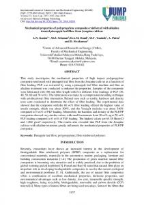
List of figures Figure 1. Tensile failure stresses and failure strains of the resins studied. Figure 2. Tensile behaviour. Stress-strain plots for three resins. Figure 3. Failure strain versus fibre content Figure 4. Fibre distribution in composite showing resin and fibre rich zones and variation of glass fiber diameter. Figure 5. Transverse tensile failure strain versus matrix failure strain. Figure 6. Example of tensile stress-strain curve for glass mat/polyester composite. Figure 7. Initial Young’s modulus in tension for glass mat/polyester composites versus fibre Figure 8. Tensile failure stress for glass mat/polyester versus fibre content. Figure 9. Tensile failure strain for glass mat/polyester versus fibre content. Figure 10. Composite strain at onset of non-linearity versus matrix failure strain. Figure 11. Glass mat/polyester. Ratio of stress at non-linearity to failure stress.
14/03/07
ACMA430 Revised
17
Reference SO1 SO2 LS LE
Product
Supplier
Resin type
Type
Polylite 420-731 Synolite 3785-L1 Synolite 8388-L7 Polylite 505-M800
Reichhold DSM DSM Reichhold
polyester orthophthalic polyester orthophthalic polyester orthophthalic DCPD polyester orthophthalic
LES
Synolite 8388-P1
DSM
polyester orthophthalic DCPD
DSM Reichhold DSM
polyester isophthalic vinylester vinylester
standard standard Low styrene content Low styrene emission Low styrene content emission standard standard standard
Synolite 3720-I1 SI Dion 9100-700 SV1 Atlac 580 ACT SV2 Table 1. Resins studied.
&
14/03/07
ACMA430 Revised
Standard Orthophthalic Polyester (SO1) DSC Cycle
Tg 1st cycle (°C)
Degree of cure (%)
Tg 2nd cycle (°C)
DMA Tan Delta at 20°C
21 days 42.9 ± 2.3 86.3 ± 0.3 96.9 ± 0.1 0.040 ± 0.002 ambient 42 days 51.8± 0.7 91.9 ± 0.4 101.3 ± 1.7 0.039 ± 0.002 ambient 63 days 62.3 1.4 91.4 ± 0.4 95.7 ± 0.4 0.033 ± 0.001 ambient 57.8 ± 0.8 88.9 ± 0.4 97.7 ± 1.4 0.037 ± 0.001 16 h 40°C 62.7 ± 0.5 90.9 ± 0.6 96.2 ± 0.9 0.034 ± 0.002 48 h 40°C 77.8 ± 1.6 95.2 ± 0.8 97.9 ± 0.5 0.024 ± 0.002 72 h 50°C Table 2. Results of DSC, DMA and tensile tests for SO1 resin
18
Tensile tests E (MPa)
Failure stress (MPa)
Failure strain (%)
2491 ± 213
46.2 ± 4.7
3.5 ± 0.3
2695 ± 64
46.9 ± 6.5
2.3 ± 0.5
2757 ± 87
48.5 ± 3.2
2.3 ± 0.3
3077 ± 192 3152 ± 79 3447 ± 75
49.4 ± 7.1 46.7 ± 2.9 49.7 ± 4.1
2.1 ± 0.5 1.9 ± 0.2 1.7 ± 0.2
14/03/07
ACMA430 Revised
Low styrene content Orthophthalic Polyester (LS) DSC DMA Cycle
Tg 1st cycle (°C)
Degree of cure (%)
Tg 2nd cycle (°C)
Tan Delta at 20°C
21 days 41.7 ± 0.5 86.7 ± 0.2 106.3 ± 0.6 0.033 ± 0.001 ambient 42 days 53.2 ± 1.5 87.4 ± 0.8 93.0 ± 4.5 0.030 ± 0.002 ambient 63 days 61.3 ± 3.4 91.2 ± 0.3 105.3 ± 1.2 0.028 ± 0.001 ambient 62.7 ± 2.2 89.1 ± 1.7 103. 7 ± 0.2 0.034 ± 0.003 16 h 40°C 65.2 ± 0.8 92.3 ± 2.4 101.2 ± 1.1 0.027 ± 0.001 48 h 40°C 76.0 ± 0.9 95.5 ± 0.1 99.7 ± 0. 9 0.023 ± 0.001 72 h 50°C Table 3. Results of DSC, DMA and tensile tests for LS resin.
19
Tensile tests E (MPa)
Failure stress (MPa)
Failure strain (%)
2926 ± 128 39.1 ± 6.4
1.6 ± 0.3
3011 ± 37
29.6 ± 3.4
1.1 ± 0.1
3334 ± 71
26.9 ± 4.2
1.1 ± 0.2
3120 ± 188 30.2 ± 7.2 3121 ± 75 26.2 ± 5.6 3788 ± 174 26.6 ± 7.1
1.2 ± 0.4 0.9 ± 0.2 0.8 ± 0.2
14/03/07
References [37] [38] [36] [18] Experimental results present study
ACMA430 Revised
20
Admissible strain 0.2 % 0.2 to 0.25 % 0.3 % (0.2 Amu) to (0.3 Amu) Transverse tensile failure strain for UD composite AUDT = 0.07 Amu + 0.17 Onset of non-linearity in tension of glass mat reinforced composite A mat lim = 0.09 Amu + 0.13 Table 4. Admissible strains proposed for glass/polyester composites. Published values and experimental results (Amu : matrix failure strain).
14/03/07
ACMA430 Revised
Figure 1. Tensile failure stresses and failure strains of the resins studied.
21
14/03/07
ACMA430 Revised
22
Stress (MPa)
.
80
60
40
20
SV2 SO1 LS
0 0
1
2 Elongation (%)
Figure 2. Tensile behaviour. Stress-strain plots for three resins.
3
4
ACMA430 Revised
23
.
14/03/07
0.4
UD 's ultimate elongation (%)
0.3
0.2
0.1
0.0 20
30
40
50
Fibre volume fraction (%)
Figure 3. Failure strain versus fibre content
60
70
14/03/07
ACMA430 Revised
24
Figure 4. Fibre distribution in composite showing resin and fibre rich zones and variation of glass fibre diameter.
ACMA430 Revised
25
.
14/03/07
0.5
UD's ultimate elongation (%)
0.4 0.3 0.2 0.1 0 0
1
2
3
4
Matrix ultimate elongation (%) Figure 5. Transverse tensile failure strain versus matrix failure strain.
14/03/07
ACMA430 Revised
26
80
Stress (MPa)
.
60
40
20
0 0
0.002
0.004
0.006
0.008
0.01
0.012
Strain
Figure 6. Example of tensile stress-strain curve for glass mat/polyester composite.
14/03/07
ACMA430 Revised
27
.
12000
CSM Young's modulus (MPa)
10000 8000
6000
4000 Experimental data
2000
D. Gay 0 10
15
20
25
30
Fibre volume fraction (%)
Figure 7. Initial Young’s modulus in tension for glass mat/polyester composites versus fibre content.
14/03/07
ACMA430 Revised
28
140
.
120
CSM ultimate stress (MPa)
100 80 60 40 Standard polyester
20
Limiting styrene emission polyester 0 10
12
14
16
18
20
Fibre volume fraction (%)
Figure 8. Tensile failure stress for glass mat/polyester versus fibre content.
22
14/03/07
ACMA430 Revised
29
.
2.5
CSM ultimate elongation (%)
2
1.5
1
0.5
Standard polyester Limiting styrene emission polyester
0 10
12
14
16
18
20
Fibre volume fraction (%) Figure 9. Tensile failure strain for glass mat/polyester versus fibre content.
22
Composite strain at non-linearity (%)
.
14/03/07
ACMA430 Revised
30
0.5
0.4
0.3
0.2
0.1
0 0
1
2
3
4
Matrix ultimate elongation (%) Figure 10. Composite strain at onset of non-linearity versus matrix failure strain.
Ratio stress non-linear/failture (%)
.
14/03/07
ACMA430 Revised
31
40
30
20
10
0 LES
LS
SO1
SV2
Figure 11. Glass mat/polyester. Ratio of stress at non-linearity to failure stress.