MECHANICAL SYSTEM MODELLING OF ROBOT DYNAMICS USING A MASS/PULLEY MODEL L. J. Stocco and M. J. Yedlin The Department of Electrical and Computer Engineering, The University of British Columbia 2332 Main Mall, Vancouver, BC, Canada, V6T 1Z4
[email protected],
[email protected]
Keywords:
Mass matrix, inertia matrix, MP model, pulley, differential transmission, mechanical system representation, robot dynamics, impedance, equivalent electric circuit.
Abstract:
The well-known electro-mechanical analogy that equates current, voltage, resistance, inductance and capacitance to force, velocity, damping, spring constant and mass has a shortcoming in that mass can only be used to simulate a capacitor which has one terminal connected to ground. A new model that was previously proposed by the authors that combines a mass with a pulley (MP) is shown to simulate a capacitor in the general case. This new MP model is used to model the off-diagonal elements of a mass matrix so that devices whose effective mass is coupled between more than one actuator can be represented by a mechanical system diagram that is topographically parallel to its equivalent electric circuit model. Specific examples of this technique are presented to demonstrate how a mechanical model can be derived for both a serial and a parallel robot with both two and three degrees of freedom. The technique, however, is extensible to any number of degrees of freedom.
1
INTRODUCTION
The concept of impedance and its generalization reactance, has been used to define equivalent circuits of mechanical and electro-mechanical systems since the development of the Maxwell model of solids. The idea that driving point impedances could be decomposed into terms that parallel electrical elements was initiated by (Foster, 1924) who showed that the frequency response of any system is determined by the poles and zeros of its transfer function. The conditions for network synthesis are described by (Brune, 1931) and later applied by (Paynter 1961) who introduced bond graphs to distinguish and represent effort and flow variables in a graphical setting. Examples of electro-mechanical system simulations are numerous and include magnetic circuits (Hamill, 1993), mechatronics and electromechanical transducers (Tilmans, 1996), (van Amerongen & Breedveld, 2003), (Sass et al., 2004). Mechanical block diagrams are routinely used to model robot dynamics although some (Eppinger & Seering, 1992) limit them to a single axis while others (Yamakita et al., 1992) rely entirely on equivalent electric circuits to avoid the inherent difficulties of creating mechanical models of multiaxis devices, transmission systems or other systems
with coupled dynamics. Section 2 of this paper describes the conventional electro-mechanical analogy and points out a limitation of the mass model. It goes on to describe a new mass/pulley (MP) model which overcomes the inherent deficiency in the conventional mass model. In Section 3, it is shown how the new MP model can be used to model the dynamics of devices which have coupled effective masses. Examples are provided which include both 2-DOF and 3-DOF serial and parallel manipulators. Lastly, concluding remarks are made in Section 4.
2
ELECTRO-MECHANICAL ANALOGIES
The ability to define an electro-mechanical equivalent circuit stems from the parallelism in the differential equations that describe electrical and mechanical systems, each of which involve an across variable, a through variable and an impedance or admittance variable. In electrical circuits, voltage E(s) is the across variable and current I(s) is the through variable. In mechanical systems, velocity V(s) is the across variable and force F(s) is the through variable (i.e. flow variable
25
ICINCO 2007 - International Conference on Informatics in Control, Automation and Robotics
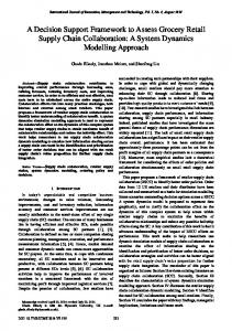
(Fairlie-Clarke, 1999)). This results in a correspondence between resistance R and damping B, inductance L and spring constant K, and capacitance C and mass M shown in (1-3). An alternate approach treats force as the across variable and velocity as the through variable but that approach is not used here. By (1-3), the electromechanical equivalents shown in Figure 1 can be substituted for one another to model a mechanical system as an electrical circuit and vise versa.
terminal open circuited.
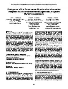
Figure 3: RC circuit and mechanical equivalent.
In Figure 3, the capacitor carries no current and therefore, has no effect on the output voltage eo. In other words, the voltages at n1and n2 are equal so the capacitor behaves like a short circuit. In the mechanical “equivalent”, it is not possible to connect a non-zero mass M to node n1 without affecting the output velocity vo. This is due to the implicit ground reference of the mass (shown by a dotted line) which prevents it from ever behaving like a mechanical short circuit. Note that this same limitation does not apply to the spring or damper since they both act as a mechanical short circuit (infinitely stiff connection) if one terminal is left unconnected, just like their electrical counterparts, the inductor and resistor. Figure 1: Admittance of electro-mechanical equivalents.
2.1
Classical Mass Model Limitation
Each of the components in Figure 1 has two terminals except for the mass which has only one. This is due to the fact that the dynamic equation of a mass (3) does not accommodate an arbitrary reference. Acceleration is always taken with respect to the global reference, or ground. Consider the two systems in Figure 2 which are well known to be analogous.
Figure 2: LC circuit and mechanical equivalent.
In Figure 2, the voltage across the capacitor ec corresponds to the velocity of the mass v. Both of these are relative measurements that only correspond to one another because both are taken with respect to ground. Consider, on the other hand, the circuit in Figure 3 which contains a capacitor with one
26
2.2
The Mass/Pulley (MP) Model
Because of the above limitation, there are mechanical systems which can not be modelled using a mechanical system diagram. Elaborate transmission systems such as robotic manipulators may contain mass elements that are only present when relative motion occurs between individual motion stages. Currently, systems such as these can only be modelled using electric circuits since capacitors can be used to model this type of behaviour but masses cannot. It would be useful to have a mechanical model which simulates the behaviour of a capacitor without an implicit ground connection so that any mechanism (or electric circuit) could be modelled by a mechanical system diagram. This new model should have two symmetric terminals (i.e. flipping the device over should not affect its response), obey Ohm’s Law, and be able to accommodate non-zero velocities at both terminals simultaneously. A model proposed by the authors (Stocco & Yedlin, 2006) combines a mass with the pulley-based differential
MECHANICAL SYSTEM MODELLING OF ROBOT DYNAMICS USING A MASS/PULLEY MODEL
transmission shown in Figure 4. The pulley system obeys the differential position / velocity relationship shown in (4,5).
Figure 4: Pulley based differential transmission.
MP model operates in zero gravity so the mass is only accelerated as a result of cable tension and/or compression. Unlike practical cables, the ideal cables never become slack. When an attractive force is applied between n1 and n2, F