minor differences in the surface oxide on fatigue crack initiation. KEY WORDS: Fatigue crack initiation, fatigue life, light water reactor, austenitic stainless steel, ...
Transactions of the 17th International Conference on Structural Mechanics in Reactor Technology (SMiRT 17) Prague, Czech Republic, August 17 –22, 2003
Paper # D03-4
Mechanism of Fatigue Crack Initiation in Austenitic Stainless Steels in Light Water Reactor Environments O. K. Chopra,1 W. J. Shack,1 and J. Muscara2 1)
Energy Technology Division, Argonne National Laboratory 9700 South Cass Avenue, Argonne, Illinois 60439 USA 2) Office of Nuclear Regulatory Research, U.S. Nuclear Regulatory Commission, Washington, DC 20555
ABSTRACT This paper examines the mechanism of fatigue crack initiation in austenitic stainless steels (SSs) in light water reactor (LWR) coolant environments. The effects of key material and loading variables on the fatigue lives of wrought and cast austenitic SSs in air and LWR environments have been evaluated. The influence of reactor coolant environments on the formation and growth of fatigue cracks in polished smooth SS specimens is discussed. The results indicate that the fatigue lives of these steels are decreased primarily by the effects of the environment on the growth of cracks 0.04 ppm DO) and only moderate (less than a factor of 2 decrease in life) in low–DO water. The reduction in fatigue life of carbon and low–alloy steels in LWR environments has been explained by the slip oxidation/dissolution mechanism for crack advance [16]. The requirements for the model are that a strain increment occur to rupture the protective surface oxide film and thereby expose the underlying matrix to the environment; once the passive oxide film is ruptured, crack extension is controlled by dissolution of freshly exposed surfaces and their oxidation characteristics. Unlike the case of carbon and low–alloy steels, environmental effects on the fatigue lives of austenitic SSs are significant in low–DO (i.e., ∆σ1
0.4
0.6
0.8
Non– Propagating Cracks
∆σ 1 LEFM
1
Life Fraction
Crack Length
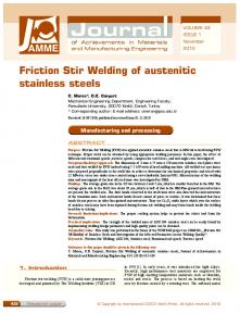
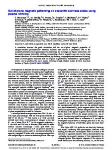
(a) (b) Figure 1. Schematic illustration of (a) growth of short cracks in smooth specimens as a function of fatigue life fraction and (b) crack velocity as a function of crack length. LEFM = linear elastic fracture mechanics; MSC = microstructurally small cracks. At low stress levels, e.g., ∆σ1 in Fig. 1b, the transition from MSC growth to accelerating crack growth does not occur. This circumstance represents the fatigue limit for the smooth specimen. Although cracks can form below the fatigue limit, they can grow to engineering size only at stresses greater than the fatigue limit. However, cracks larger than the transition length, either preexisting, e.g., defects in welded samples, or those created by growth of MSCs at high stresses, can grow at stress levels below the fatigue limit. GROWTH RATES OF SMALL CRACKS IN LWR ENVIRONMENTS Studies on growth of short cracks in smooth fatigue specimens in LWR environments [17] indicate that at the same number of cycles, the crack length is longer in low–DO (PWR) water than in air (Fig. 2). For example, after 1500 cycles the crack length in air, high-DO (BWR) water, and low–DO (PWR) water is ≈40, 300, and 1100 µm, respectively. The growth of cracks during the initiation stage, i.e., growth of MSCs, is enhanced in water; fatigue cycles needed to form a 500–µm crack are a factor of ≈12 lower in low–DO water than in air. Figure 2 shows that the number of cycles required to produce a 500–µm crack is 800, 3000, and 9,000 in low–DO, high-DO, and air environments, respectively; thus, the number of cycles is more than a factor of 10 lower in low–DO water than in air. 5
10
o
Type 304 SS, 288 C, Strain Range: 0.75% PWR BWR Air Air (calc) o Type 316L SS, 25 C, Strain Range: 0.2%
4
Crack Depth (µm)
10
Air 3
10
2
10
101
103
104 105 Number of Cycles
106
Figure 2. Depth of largest crack plotted as a function of fatigue cycles for austenitic stainless steels in air and water (Refs. 23,27) 3
The crack growth rates (CGRs) during the propagation stage, i.e., growth of mechanically small cracks, in air and water environments are plotted as a function of crack length in Fig. 3; they were calculated from the best fit of the data in Fig. 2. In high–DO water, the CGRs of a specimen that was soaked only for 24 h (closed diamonds in Fig. 3) instead of 120 h are also included in the figure; for this specimen, growth rates were determined from measurements of fatigue striations on the fracture surface. The CGRs are a factor of 2–6 higher in water than in air. Growth rates in PWR water or high–DO water with a 24–h soak period are higher than those in high–DO water with a 120–h soak period. At a crack length of ≈1000 µm, the CGRs in air, high–DO water, and low–DO PWR environment are 0.30, 0.64, and 1.05 µm/cycle, respectively. For the 0.75% strain range and 0.004%/s strain rate, these values correspond to growth rates of ≈1.6 x 10⁻⁹, 3.4 x 10⁻⁹, and 5.6 x 10⁻⁹ m/s in air, high–DO water, and low–DO water, respectively. Growth rates are a factor of 3.5 greater in low–DO water than in air. 0
10
Estimated
-1
PWR High–DO Water Air (Estimated)
Crack Growth Rate ( µm/Cycle)
Crack Growth Rate ( µm/Cycle)
Austenitic SS Air
Type 304 SS 288°C 0.75% Strain Range: Strain Rate: 0.004%/s
101
100
10
-2
10
-3
10
Strain Range Type 304 SS 288°C 0.75% 0.24%
-1
10
Open Circles: 120-Soak Closed Circles: 24-h Soak 2
10
Type 316L SS 25°C
-4
10 3
10
0.20% 1
4
10
10
Crack Length ( µm)
2
10
3
10
4
10
Crack Length (µm)
Figure 3. Crack growth rates plotted as a function of crack length for stainless steels in air and water environments (Refs. 23,27) The CGRs determined from the ε–N tests are consistent with the data obtained from fracture–mechanics tests [28]. However, the large reductions in fatigue life of austenitic SSs in PWR environments cannot be explained entirely on the basis of enhanced CGRs during the propagation stage, i.e., growth of mechanically small cracks. For example, the CGRs in low–DO water are a factor of 1.6 greater than those in high–DO water, but the fatigue life is a factor of ≈4 lower in low–DO water than in high–DO water. As shown in Fig. 2, the decrease in fatigue lives of austenitic SSs in PWR environments is caused predominantly by the effects of environment on the growth of cracks