Tese (Doutorado) - Escola Politécnica da Universidade de ... ateliê oferece um
repositório de fragmentos de método que contempla distintas fases de ...
Sara Jane Casare
MEDEE: A METHOD FRAMEWORK FOR MULTIAGENT SYSTEMS
Tese apresentada à Escola Politécnica da Universidade de São Paulo para a obtenção do Título de Doutor em Ciências
São Paulo 2012
Sara Jane Casare
MEDEE: A METHOD FRAMEWORK FOR MULTIAGENT SYSTEMS
Tese apresentada à Escola Politécnica da Universidade de São Paulo para a obtenção do Título de Doutor em Ciências
Área de Concentração: Sistemas Digitais
Orientador:
Prof. Dr. Jaime Simão Sichman
São Paulo 2012
Este exemplar foi revisado e alterado em relação à versão original, sob responsabilidade única do autor e com a anuência de seu orientador. São Paulo, 27 de janeiro de 2012.
Assinatura do autor ____________________________
Assinatura do orientador _______________________
FICHA CATALOGRÁFICA
Casare, Sara Jane Medee: a method framework for the multiagent systems / S.J. Casare. -- ed.rev. -- São Paulo, 2012. 285 p. Tese (Doutorado) - Escola Politécnica da Universidade de São Paulo. Departamento de Engenharia de Computação e Sistemas Digitais. 1. Sistemas multiagentes 2. Agentes inteligentes 3. Engenharia de software 4. Engenharia de método 5. Fragmento de método I. Universidade de São Paulo. Escola Politécnica. Departamento de Engenharia de Computação e Sistemas Digitais II. t.
A os m eus pais, W arner e D elurdes A o A ndrei
« Le texte, c’est la trace écrite qui fait qu’une œuvre dépasse, dans une certaine mesure, l’intention subjective de son auteur. Dans la production même de son œuvre, l’auteur dit plus qu’il ne croit dire » (DEJOURS, 2010, p. 96).
Acknowledgements
It’s with great pleasure that I thank the all the people who made this thesis possible. For Professor Jaime Sichman, for his careful and thorough guidance. In addition, I thank Jaime for his friendship during my eight years of research at the Laboratório de Tecnicas Inteligentes (LTI). Professor Zahia Guessoum, for the welcome I received at the Laboratoire d'informatique de Paris 6 (LIP6) and for her guidance during the research period I undertook at the lab. Anarosa Brandão for friendship and support in this important piece of work, especially during the preparation and execution of the case study. Professors Selma Melnikoff, Viviane Torres da Silva, Jomi Fred Hübner, and Jeferson Soares for having accepted to be members of my jury and for having honored me with their presence Also, Professor Carlos Lucena for his valuable comments and suggestions on my qualifying exam. I am privileged and thankful for their careful reading and thoughtful comments. For the staff and fellow researchers at LIP6. A special thanks to Amel Boustil, Javier Gil-Quijano and Hélène Giroire. To my colleagues at LTI, especially Gustavo Pacianotto for his support in conducting the case study. To my managers at IBM, Antonio Froes and Eduardo Villela, who made it possible for me to take a year out to study. CAPES, FAPESP and the Post Graduate Program in Electrical Engineering from the Polytechnic School at USP, for financial support. Finally, I thank my family for their understanding and unconditional support over the years. (agradeço a minha familia pela compreensão e apoio incondicional ao longo de todos esses anos).
Resumo
Esta tese propõe o desenvolvimento de SMAs centrados em organizações de forma disciplinada, mesmo nos casos em que os modelos organizacionais de agentes utilizados não estejam incorporados aos métodos oferecidos pela Engenharia de Software Orientada a Agentes (AOSE). A fim de atingir tal objetivo, esta tese adota os principios da Engenharia de Método Situational e propõe o Ateliê Medee, que permite a composição de métodos situacionais para SMAs usando fragmentos de método adequados à situação de cada projeto. Este ateliê oferece um repositório de fragmentos de método que contempla distintas fases de desenvolvimento de um projeto, tais como elucidação de requisitos, análise, design, e implementação, envolvendo os principais componentes de um SMA, como agentes, ambientes, interações e organizações. Tal repositório contém fragmentos extraidos de diversas abordagens para o desenvolvimento de SMAs, entre elas os métodos Gaia, Tropos, Ingenias, PASSI, e os modelos organizacionais MOISE+ e OperA. Além disso, esta tese mostra como tais métodos situationais podem contribuir no estabelecimento de um ciclo de melhoria do método de desenvolvimento para SMAs. Este ciclo aplica os principios da Engenharia de Software a fim de prover um procedimento empirico para a adaptação, avaliação e melhoria de métodos situacionais para o desenvolvimento de SMAs centrados em organizações. Dessa forma, este ciclo contribui para uma utilização mais ampla de aplicações orientadas a agentes pela indústria.de software. Finalmente, esta tese apresenta um estudo de caso conduzido para investigar o uso do Ateliê Medee na composição de métodos situacionais para SMAs. Este estudo de caso envolveu o desenvolvimento de SMAs centrados em organizações para resolver o problema proposto pelo Torneio de Programação Multiagentes usando dois métodos situacionais distintos, compostos a partir de fragmentos de método extraídos de Tropos, Gaia e MOISE+.
Abstract
This thesis proposes the development of organization centered MAS in a disciplined way, even though some agent organizational models are not currently incorporated into AOSE methods. In order to do that, this thesis proposes the Medee Framework for composing MAS situational methods out of method fragments according to a given project situation,
by applying the principles
proposed by Situational Method Engineering. Thus, it offers a method fragment repository that covers different development phases, like requirements, analysis, design, implementation, as well as the main components of a MAS application, such as agents, environments, interactions, and organizations. Such a repository has been sourced from several MAS development approaches, as such Gaia, Tropos, Ingenias, PASSI, MOISE, and OperA. Furthermore, this doctoral dissertation shows how such MAS situational methods could contribute to establish a method improvement cycle. Such a cycle applies principles of the Software Engineering discipline to provide an empirical procedure for tailoring, evaluating, and enhancing MAS situational methods. In this way, this cycle allows the continuous improvement of the Medee Method Repository, towards a steady and well founded path for MAS method maturation and, consequently, for a broader utilization of agent-oriented software development in the software industry. Finally, this dissertation presents a case study conducted to investigate the use of the Medee Framework for composing MAS situational methods, sourced mainly from Tropos, Gaia, and MOISE+. Moreover, these situational methods were used within an improvement cycle for MAS development methods. This case study, called the USP Farmer project, involved the development of organization centered MAS to solve the problem proposed by the Multiagent Programming Contest.
List of Figures
FIGURE 1.1 CURRENT DEVELOPMENT SCENARIO FOR ORGANIZATION CENTERED MAS ........................................... 4 FIGURE 1.2 THREE DEVELOPMENT SCENARIOS FOR ORGANIZATION CENTERED MAS: FROM CURRENT TO TARGET . 6 FIGURE 1.3: RESEARCH OBJECTIVES IN A DIAGRAMMATICAL PERSPECTIVE.............................................................. 9 FIGURE 1.4: MAIN COMPONENTS OF THE RESEARCH APPROACH ............................................................................. 11 FIGURE 1.5: DISSERTATION STRUCTURE ................................................................................................................ 12 FIGURE 2.1: FOUR SOFTWARE ENGINEERING LAYERS (PRESSMAN, 2010, P.14)................................................. 16 FIGURE 2.2: THE PROCESS IMPROVEMENT CYCLE (SOMMERVILLE, 2007)....................................................... 19 FIGURE 2.3: QIP SIX STEPS .................................................................................................................................... 21 FIGURE 2.4: AN ABSTRACT GQM STRUCTURE COMPOSED OF GOALS, QUESTIONS AND METRIC (BASILI, 1992) .. 25 FIGURE 2.5: RUP BI-DIMENSIONAL REPRESENTATION (KRUCHTEN, 2003)......................................................... 31 FIGURE 3.1: AOSE METHODS AND THEIR RELATIONSHIP WITH OBJECT-ORIENTED PARADIGM, INSPIRED BY (GIORGINI; HENDERSON-SELLERS, 2005)........................................................................................... 49 FIGURE 4.1: AN ITERATIVE PROCEDURE FOR BUILDING SITUATIONAL METHODS, INSPIRED BY HARMSEN (1997) .. 60 FIGURE 4.2: S3 MODEL (HARMSEN, 1997) .......................................................................................................... 63 FIGURE 4.3: METHOD COMPONENT MAIN ELEMENTS .............................................................................................. 66 FIGURE 4.4: SPEM CORE CONCEPTS AND THEIR RELATIONSHIPS (HAUMER, 2007A)........................................... 69 FIGURE 4.5: SPEM KEY CONCEPTS MAPPED TO METHOD CONTENT AND PROCESS (OMG, 2008A, P.14).............. 69 FIGURE 4.6: SPEM CONCEPTUAL USAGE FRAMEWORK INSPIRED BY (OMG, 2008A, P.10)..................................... 73 FIGURE 4.7: EPF COMPOSER ARCHITECTURE, INSPIRED ON (OMG, 2008A) .......................................................... 75 FIGURE 4.8: AN EXAMPLE OF AN ACTIVITY DIAGRAM ........................................................................................... 76 FIGURE 4.9: AN EXAMPLE OF AN ACTIVITY DETAILED DIAGRAM .......................................................................... 76 FIGURE 4.10: THE SEMIOTIC LADDER (STAMPER, 1996)..................................................................................... 78 FIGURE 5.1: ELABORATING METHOD FRAGMENTS AND COMPOSING SITUATIONAL METHODS USING THE MEDEE METHOD FRAMEWORK, INSPIRED BY RALYTÉ (2001)................................................................................... 87 FIGURE 5.2: THE MAIN ELEMENTS OF MEDEE MAS SITUATIONAL METHOD AND MEDEE MAS METHOD FRAGMENT ................................................................................................................................................... 89 FIGURE 5.3: FROM THE MAS PROJECT SITUATION TO THE APPROPRIATE SITUATIONAL METHOD USING THE MEDEE COMPOSITION MODEL .................................................................................................................................. 93 FIGURE 5.4 PEOPLE FACTORS OF THE MEDEE PROJECT FACTORS TAXONOMY....................................................... 95 FIGURE 5.5: PROBLEM FACTORS OF THE MEDEE PROJECT FACTORS TAXONOMY .................................................. 96 FIGURE 5.6: PRODUCT FACTORS OF THE MEDEE PROJECT FACTORS TAXONOMY .................................................. 97 FIGURE 5.7: RESOURCE FACTORS OF THE MEDEE PROJECT FACTORS TAXONOMY ................................................ 98 FIGURE 5.8: THE FIVE LEVELS OF THE MEDEE MAS SEMIOTIC TAXONOMY .......................................................... 99 FIGURE 5.9: SOCIAL LEVEL OF THE MEDEE MAS SEMIOTIC TAXONOMY ............................................................. 100
FIGURE 5.10: PRAGMATIC LEVEL OF THE MEDEE MAS SEMIOTIC TAXONOMY.................................................... 101 FIGURE 5.11: SEMANTIC LEVEL OF THE MEDEE MAS SEMIOTIC TAXONOMY ...................................................... 103 FIGURE 5.12: SYNTACTIC LEVEL OF THE MEDEE MAS SEMIOTIC TAXONOMY .................................................... 104 FIGURE 5.13: EMPIRICAL LEVEL OF THE MEDEE MAS SEMIOTIC TAXONOMY ..................................................... 104 FIGURE 5.14: INSTABLE REQUIREMENTS GUIDELINE ........................................................................................... 106 FIGURE 5.15: MAIN CONCEPTS OF THE MEDEE METHOD FRAMEWORK DEPICTED THROUGH A UML CLASS DIAGRAM .................................................................................................................................................... 109
FIGURE 5.16: THE MEDEE MAS WORK PRODUCT FRAMEWORK DEPICTED THROUGH A UML CLASS DIAGRAM .. 110 FIGURE 5.17: THE MAS ACTIVITY METHOD FRAGMENT DEPICTED THROUGH A UML CLASS DIAGRAM ............. 112 FIGURE 5.18: THE MAS ITERATION METHOD FRAGMENT DEPICTED THROUGH A UML CLASS DIAGRAM............ 113 FIGURE 5.19: THE MAS PHASE METHOD FRAGMENT DEPICTED THROUGH A UML CLASS DIAGRAM .................. 115 FIGURE 5.20: THE MAS PROCESS METHOD FRAGMENT DEPICTED THROUGH A UML CLASS DIAGRAM............... 116 FIGURE 5.21: THE MEDEE MAS SITUATIONAL METHOD DEPICTED THROUGH A UML CLASS DIAGRAM ............. 117 FIGURE 5.22: THE MEDEE COMPOSITION MODEL DEPICTED THROUGH A UML CLASS DIAGRAM......................... 118 FIGURE 6.1: MAIN COMPONENTS OF THE MEDEE FRAMEWORK............................................................................ 122 FIGURE 6.2: THREE PILLARS OF THE MEDEE METHOD REPOSITORY..................................................................... 124 FIGURE 6.3: THE MEDEE METHOD REPOSITORY DEPICTED THROUGH A UML CLASS DIAGRAM .......................... 126 FIGURE 6.4: THE MEDEE ELEMENTS PILLAR DEPICTED THROUGH A UML CLASS DIAGRAM................................. 127 FIGURE 6.5: THE MEDEE FRAGMENT PILLAR DEPICTED THROUGH A UML CLASS DIAGRAM ................................ 129 FIGURE 6.6: MEDEE MAS SEMIOTIC TAXONOMY, DESCRIBING THE VALIDATION DEGREE CATEGORY ............... 130 FIGURE 6.7: MEDEE COMMON ROLES, DESCRIBING THE MAS DESIGNER ROLE .................................................... 131 FIGURE 6.8: MEDEE WORK PRODUCT SLOTS, DESCRIBING THE MPS ORGANIZATION ANALYSIS ........................ 133 FIGURE 6.9: MAS WORK PRODUCT VARIABILITY FOR EXTENDING TROPOS ........................................................ 135 FIGURE 6.10: MAS WORK PRODUCT VARIABILITY FOR EXTENDING MOISE+ .................................................... 135 FIGURE 6.11: MAS TASK VARIABILITY FOR EXTENDING MOISE+...................................................................... 136 FIGURE 6.12: MTV ANALYZE MAS ORGANIZATION, AFTER THE FULFILLMENT OF INPUT WORK PRODUCTS ....... 136 FIGURE 6.13: THE MEDEE METHODS PILLAR DEPICTED THROUGH A UML CLASS DIAGRAM................................ 137 FIGURE 6.14: SOME TERM DEFINITIONS OF THE MEDEE GLOSSARY ..................................................................... 138 FIGURE 6.15: THE THREE ELEMENTS OF THE MEDEE COMPOSITION MODEL AND THEIR RELATIONSHIPS ............. 139 FIGURE 6.16: MEDEE DELIVERY PROCESS ACTIVITY DIAGRAM ........................................................................... 140 FIGURE 6.17: METHOD ELEMENT CAPTURE PHASE REPRESENTED AS AN ACTIVITY DIAGRAM ............................. 141 FIGURE 6.18: CAPTURE METHOD CONTENT ACTIVITY DETAILED DIAGRAM ......................................................... 142 FIGURE 6.19: BUILD AOSE METHOD AS IS ACTIVITY DETAILED DIAGRAM ........................................................ 144 FIGURE 6.20: PUBLISHED AOSE METHOD AS IS ACTIVITY DETAILED DIAGRAM ............................................... 145 FIGURE 6.21: METHOD FRAGMENT ELABORATION PHASE ACTIVITY DIAGRAM ................................................... 146 FIGURE 6.22: CREATE ACTIVITY METHOD FRAGMENT ACTIVITY DETAILED DIAGRAM ........................................ 147 FIGURE 6.23: CREATE INTERMEDIATE METHOD FRAGMENT ACTIVITY DETAILED DIAGRAM................................ 149 FIGURE 6.24: CREATE PROCESS METHOD FRAGMENT ACTIVITY DETAILED DIAGRAM ......................................... 150 FIGURE 6.25: MEDEE METHOD COMPOSITION PHASE ACTIVITY DIAGRAM .......................................................... 151 FIGURE 6.26: CHARACTERIZE MAS PROJECT SITUATION ACTIVITY DETAILED DIAGRAM .................................... 152
FIGURE 6.27: SELECT CANDIDATE MAS METHOD FRAGMENT ACTIVITY DETAILED DIAGRAM ............................ 153 FIGURE 6.28: COMPOSE MAS SITUATIONAL METHOD ACTIVITY DETAILED DIAGRAM......................................... 155 FIGURE 6.29: PUBLISH MAS SITUATIONAL METHOD ACTIVITY DETAILED DIAGRAM .......................................... 156 FIGURE 6.30: GENERATE MEDEE AOSE METHOD ACTIVITY DETAILED DIAGRAM .............................................. 157 FIGURE 6.31: THE SEVEN STEPS OF THE MEDEE IMPROVEMENT CYCLE ............................................................... 160 FIGURE 6.32: BIG PICTURE OF THE MEDEE IMPROVEMENT CYCLE, INSPIRED BY SOMMERVILLE (2007)............. 165 FIGURE 7.1: ELABORATING METHOD FRAGMENTS USING THE MEDEE METHOD FRAMEWORK ............................. 170 FIGURE 7.2: GAIA MODELS AND THEIR RELATIONSHIPS WITH THE DEVELOPMENT PHASES (ZAMBONELLI; JENNINGS; WOOLDRIDGE, 2003) ........................................................................................................ 171 FIGURE 7.3: TASKS AND WORK PRODUCTS CAPTURED FROM GAIA, DETAILING THE DEFINE AGENT MODEL TASK. ................................................................................................................................................................... 174 FIGURE 7.4: GUIDANCE CAPTURED FROM GAIA, DETAILING THE AGENT CONCEPT .............................................. 175 FIGURE 7.5: GAIA AS IS PUBLISHED BY EPF COMPOSER ...................................................................................... 175 FIGURE 7.6: MAS WORK PRODUCT VARIABILITY FOR GAIA, DETAILING THE MPV GAIA AGENT DESIGN MODEL ...... 177 FIGURE 7.7: MAS TASK VARIABILITY FOR GAIA, DETAILING THE MTV DEFINE AGENT MODEL ................................. 177 FIGURE 7.8: MAS ACTIVITY METHOD FRAGMENTS SOURCED FROM GAIA, DETAILING MMF DESIGN AGENT WITH GAIA ................................................................................................................................................................... 179 FIGURE 7.9: MAS PHASE METHOD FRAGMENTS SOURCED FROM GAIA, DETAILING THE MMF DESIGN PHASE WITH GAIA ................................................................................................................................................................... 180 FIGURE 7.10: MILESTONE OF THE MMF DESIGN PHASE WITH GAIA............................................................................. 180 FIGURE 7.11: MAS PROCESS METHOD FRAGMENTS SOURCED FROM GAIA, DETAILING THE MMF GAIA BASE METHOD ................................................................................................................................................................... 181 FIGURE 7.12: TROPOS PHASES AND WORK PRODUCTS .......................................................................................... 183 FIGURE 7.13: TASKS AND WORK PRODUCTS CAPTURED FROM TROPOS, DETAILING THE IDENTIFY STAKEHOLDERS TASK ........................................................................................................................................................... 185
FIGURE 7.14: GUIDANCE CAPTURED FROM TROPOS, DETAILING THE ACTOR MODELING GUIDELINE ................... 186 FIGURE 7.15: TROPOS AS IS PUBLISHED BY THE EPF COMPOSER ......................................................................... 187 FIGURE 7.16: MAS WORK PRODUCT VARIABILITY FOR TROPOS, DETAILING THE MPV TROPOS ACTOR DIAGRAM ..... 189 FIGURE 7.17: MAS TASK VARIABILITY FOR TROPOS, DETAILING MTV IDENTIFY STAKEHOLDERS ............................. 189 FIGURE 7.18: MAS ACTIVITY METHOD FRAGMENTS SOURCED FROM TROPOS, DETAILING THE MMF IDENTIFY INITIAL REQUIREMENTS WITH TROPOS .......................................................................................................................... 190 FIGURE 7.19: MAS PHASE METHOD FRAGMENTS SOURCED FROM TROPOS, DETAILING THE MMF REQUIREMENTS PHASE WITH TROPOS ...................................................................................................................................... 191 FIGURE 7.20: MAS METHOD FRAGMENTS SOURCED FROM TROPOS, ORGANIZED IN THE MMF TROPOS BASE METHOD ................................................................................................................................................................... 192 FIGURE 7.21 MOISE+ STRUCTURAL SPECIFICATION FOR A SOCCER TEAM (HUBNER; SICHMAN; BOISSIER, 2002, 2007) ................................................................................................................................................ 194 FIGURE 7.22: MOISE+ FUNCTIONAL SPECIFICATION FOR SCORING A SOCCER GOAL (HUBNER; SICHMAN; BOISSIER, 2002)....................................................................................................................................... 195
FIGURE 7.23: TASKS AND WORK PRODUCTS CAPTURED FROM MOISE+, DESCRIBING THE ANALYZE MAS ORGANIZATION TASK ................................................................................................................................. 197 FIGURE 7.24: GUIDANCE CAPTURED FROM MOISE+, DETAILING THE ORGANIZATION MANAGEMENT INFRASTRUCTURE FOR JASON ..................................................................................................................... 199 FIGURE 7.25: MAS WORK PRODUCT VARIABILITY FOR MOISE+, DETAILING THE MPV ORGANIZATIONAL SPECIFICATION ................................................................................................................................................................... 200 FIGURE 7.26: MAS TASK VARIABILITY FOR MOISE+, DETAILING THE MTV ANALYZE MAS ORGANIZATION............... 201 FIGURE 7.27: MAS ACTIVITY METHOD FRAGMENTS SOURCED FROM MOISE+, DETAILING THE MMF ANALYZE ORGANIZATION WITH MOISE+ .......................................................................................................................... 202 FIGURE 7.28: TASKS AND WORK PRODUCTS CAPTURED FROM USDP, DETAILING FIND ACTORS AND USE CASES TASK ........................................................................................................................................................... 204
FIGURE 7.29: MAS ACTIVITY METHOD FRAGMENTS SOURCED FROM USDP, DETAILING THE MMF IDENTIFY REQUIREMENTS WITH USDP............................................................................................................................. 205 FIGURE 8.1: MAS ENVIRONMENT COMPOSED BY COWBOYS (RED AND BLUE TRIANGLES), FENCES (GREEN OVALS), COWS (WHITE OVALS), AND OBSTACLES (BEHRENS ET AL., 2009) ........................................................... 212
FIGURE 8.2: APPLYING THE MEDEE IMPROVEMENT CYCLE TO THE USP FARMER PROJECT ................................ 214 FIGURE 8.3: GQM MODEL FOR USP FARMER PROJECT, INSPIRED BY (BASILI; CALDIERA; ROMBACH, 1994) ................................................................................................................................................................... 220 FIGURE 8.4: TOP-DOWN SITUATIONAL COMPOSITION, DETAILING SITUATIONAL PHASES USING TROPOS AND MOISE+..................................................................................................................................................... 229 FIGURE 8.5: TROPOS-MOISE SITUATIONAL METHOD PUBLISHED AS WEB PAGES ................................................. 230 FIGURE 8.6: BOTTOM-UP SITUATIONAL COMPOSITION, DETAILING SITUATIONAL PHASES USING GAIA, MOISE, USDP ......................................................................................................................................................... 231 FIGURE 8.7: GAIA-MOISE SITUATIONAL METHOD PUBLISHED AS WEB PAGES ..................................................... 232 FIGURE 8.8: A PARTIAL VIEW OF QUESTIONNAIRE A – DEVELOPER VIEWPOINT .................................................. 234 FIGURE 8.9: THE MOISE+ ESTIMATION CONSIDERATION, DETAILING ITS IMPLEMENTATION ESTIMATION........... 244 FIGURE 8.10: THE IMPROVED MMF IMPLEMENT AGENT WITH MOISE+ ........................................................................ 245 FIGURE 8.11: THE IMPROVED MEDEE COMPOSITION MODEL ............................................................................... 245 FIGURE 8.12: IMPROVING MEDEE MAS METHOD FRAGMENTS SOURCED FROM TROPOS AND MOISE+............... 246 FIGURE 8.13: IMPROVING MEDEE MAS METHOD FRAGMENTS SOURCED FROM GAIA AND USDP ....................... 247 FIGURE 8.14: IMPROVING MEDEE SITUATIONAL METHODS CLASSIFICATION ....................................................... 247 FIGURE 10.1: PASSI DEVELOPMENT PHASES (COSSENTINO, 2005).................................................................. 271 FIGURE 10.2: MAS METHOD FRAGMENTS SOURCED FROM PASSI, DETAILING THE MMF PASSI BASE METHOD USING USDP .......................................................................................................................................................... 272 FIGURE 10.3: METHOD FRAGMENTS SOURCED FROM INGENIAS, DETAILING THE MMF ENHANCED ELABORATION PHASE WITH INGENIAS ............................................................................................................................................... 274
FIGURE 10.4: OPERA ARCHITECTURE (DIGNUM, 2004) ..................................................................................... 276 FIGURE 10.5: MAS TASK VARIABILITY AND ACTIVITY METHOD FRAGMENTS SOURCED FROM OPERA.............. 277 FIGURE 11.1: FIRST PAGE OF QUESTIONNAIRE C – DEVELOPER VIEWPOINT ......................................................... 279 FIGURE 11.2: SECOND PAGE OF QUESTIONNAIRE C – DEVELOPER VIEWPOINT ................................................... 280
FIGURE 11.3: THIRD PAGE OF QUESTIONNAIRE C – DEVELOPER VIEWPOINT ...................................................... 280 FIGURE 11.4: FIRST PAGE OF QUESTIONNAIRE C – PROJECT MANAGER VIEWPOINT ............................................ 281 FIGURE 11.5: SECOND PAGE OF QUESTIONNAIRE C – PROJECT MANAGER VIEWPOINT ........................................ 281 FIGURE 12.1: MEDEE METHOD FRAGMENTS FOLDER AND THE FIREFOX INDEX FILE ............................................ 283 FIGURE 12.2: BROWSING MEDEE MAS METHOD FRAGMENTS.............................................................................. 283 FIGURE 12.3: BROWSING THE MEDEE SITUATIONAL METHOD CREATED DURING USP FARMER PROJECT ............. 284 FIGURE 12.4: BROWSING THE AOSE METHODS AS IS ........................................................................................... 285 FIGURE 12.5: BROWSING THE MEDEE DELIVERY PROCESS .................................................................................. 285
List of Tables
TABLE 3.1: AGENT ORGANIZATIONAL MODELS SUMMARY ..................................................................................... 46 TABLE 3.2: AOSE METHODS SUMMARY ................................................................................................................. 55 TABLE 5.1: THE MEDEE COMPOSITION GUIDELINES ............................................................................................ 107 TABLE 7.1: MEDEE METHOD REPOSITORY POPULATION SUMMARY .................................................................... 207 TABLE 8.1: USP FARMER PROJECT SITUATION - PEOPLE FACTORS ...................................................................... 215 TABLE 8.2: USP FARMER PROJECT FACTORS ASSESSMENT USING MEDEE COMPOSITION MODEL........................ 225 TABLE 8.3: THE SIX QUESTIONNAIRES FOR COLLECTING GQM METRICS ............................................................. 234 TABLE 8.4: COLLECTED GQM METRICS FROM A DEVELOPER’S VIEWPOINT ......................................................... 237 TABLE 8.5: COLLECTED GQM METRICS FROM A PROJECT MANAGER’S VIEWPOINT ............................................. 239 TABLE 8.6: LESSONS LEARNED AND .IMPROVEMENT OPPORTUNITIES - MEASUREMENT GOALS 1 TO 4 ................. 241 TABLE 8.7: LESSONS LEARNED AND .IMPROVEMENT OPPORTUNITIES - MEASUREMENT GOALS 5 TO 7 ................. 242
List of Abbreviations
ADELFE
Atelier de Développement de Logiciels à Fonctionnalité Emergente
AOSE
Agent-oriented Software Engineering
AUML
Agent Unified Model Language
CASE
Computer-Aided Software Engineering
EPF
Eclipse Process Framework
JADE
Java Agent Development Framework
MAS
Multiagent System
MOISE+
Model of Organization for Multiagent Systems
MMF
Medee MAS Method Fragment
MPS
Medee work Product Slot
MPV
Medee work Product Variability
MTV
Medee Task Variability
OMG
Object Management Group
PASSI
Process for Agent Societies Specification and Implementation
OperA
Organization Per Agent
SPEM
Software & Systems Process Engineering Meta-Model Specification
RUP
Rational Unified Process
UML
Unified Model Language
USDP
Unified Software Development Process
Table of Contents
CHAPTER 1
INTRODUCTION....................................................................................................... 1
1.1 MOTIVATION ................................................................................................................................... 1 1.1.1 Multiagent Systems Development ........................................................................................... 2 1.1.2 Quality Focus in MAS Development....................................................................................... 5 1.2 RESEARCH QUESTIONS .................................................................................................................... 7 1.3 RESEARCH APPROACH..................................................................................................................... 7 1.3.1 Situational Method Engineering............................................................................................. 8 1.3.2 Research Objective ................................................................................................................. 8 1.3.3 Research Procedure.............................................................................................................. 10 1.4 TEXT STRUCTURE.......................................................................................................................... 12 PART I BACKGROUND AND RELATED WORK ........................................................................ 14 CHAPTER 2 SOFTWARE ENGINEERING..................................................................................... 15 2.1 INTRODUCTION .............................................................................................................................. 15 2.2 SOFTWARE QUALITY FOCUS ......................................................................................................... 18 2.2.1 Overview............................................................................................................................... 18 2.2.2 Quality Improvement Paradigm ........................................................................................... 21 2.2.3 Goal Question Metric Paradigm .......................................................................................... 24 2.3 SOFTWARE DEVELOPMENT METHOD ............................................................................................ 26 2.3.1 Main notions ......................................................................................................................... 26 2.3.2 Methods Overview ................................................................................................................ 28 2.3.3 Unified Software Development Process (USDP).................................................................. 29 2.3.4 Rational Unified Process (RUP)........................................................................................... 30 2.3.5 Method Quality Attributes .................................................................................................... 32 2.4 DISCUSSION ................................................................................................................................... 33 CHAPTER 3
MULTIAGENT SYSTEMS DEVELOPMENT ...................................................... 36
3.1 INTRODUCTION ............................................................................................................................ 36 3.2 THE AGENT-ORIENTED PARADIGM ............................................................................................. 38 3.2.1 Vowel: Agent, Environment, Interaction, Organization ....................................................... 38 3.2.2 Agent Architectures .............................................................................................................. 39 3.2.3 Agent Applications............................................................................................................... 40 3.2.4 Organization Centered MAS................................................................................................. 42
3.3 AGENT ORGANIZATIONAL MODELS ............................................................................................. 43 3.3.1 Overview............................................................................................................................... 43 3.3.2 AGR ..................................................................................................................................... 44 3.3.3 MOISE+ ............................................................................................................................... 44 3.3.4 OperA .................................................................................................................................. 45 3.3.5 Islander................................................................................................................................ 45 3.3.6 Agent Organizational Models Summary............................................................................... 46 3.4 AGENT-ORIENTED SOFTWARE ENGINEERING ................................................................................ 47 3.4.1 Overview............................................................................................................................... 47 3.4.2 Gaia ...................................................................................................................................... 49 3.4.3 MaSE and O-MaSE.............................................................................................................. 50 3.4.4 Prometheus ........................................................................................................................... 51 3.4.5 Tropos.................................................................................................................................. 51 3.4.6 ADELFE .............................................................................................................................. 52 3.4.7 PASSI................................................................................................................................... 52 3.4.8 Ingenias and MESSAGE ..................................................................................................... 53 3.4.9 ASEME ................................................................................................................................. 54 3.4.10 AOSE Methods Summary................................................................................................... 54 3.5 DISCUSSION ................................................................................................................................... 56 CHAPTER 4 SITUATIONAL METHOD ENGINEERING............................................................. 58 4.1 INTRODUCTION .............................................................................................................................. 58 4.2 MAIN APPROACHES ....................................................................................................................... 60 4.2.1 Method Fragment ................................................................................................................. 61 4.2.2 Method Chunk....................................................................................................................... 63 4.2.3 Work Product Description .................................................................................................... 64 4.2.4 Method Component............................................................................................................... 65 4.3 META-MODELS, FRAMEWORKS, AND TOOLS ................................................................................. 67 4.3.1 Overview............................................................................................................................... 67 4.3.2 Software and System Process Engineering Meta-model (SPEM)......................................... 68 4.3.3 Eclipse Process Framework Composer ................................................................................ 74 4.3.4 Semiotic Ladder.................................................................................................................... 77 4.4 SITUATIONAL METHOD ENGINEERING FOR MAS .......................................................................... 78 4.4.1 Overview............................................................................................................................... 78 4.4.2 FIPA’s Approach.................................................................................................................. 79 4.4.3 Cossentino et al. Approach................................................................................................... 81 4.4.4 Henderson-Sellers et al. Approach...................................................................................... 82 4.5 DISCUSSION ................................................................................................................................... 82
PART II DEVELOPING ORGANIZATION CENTERED MULTIAGENT SYSTEMS.............. 84 CHAPTER 5 MEDEE METHOD FRAMEWORK BUILDING BLOCKS .................................... 85 5.1 INTRODUCTION .............................................................................................................................. 85 5.2 MEDEE MAS METHOD FRAGMENT AND MEDEE MAS SITUATIONAL METHOD ........................... 87 5.2.1 Definition .............................................................................................................................. 87 5.2.2 Main Elements ...................................................................................................................... 89 5.2.3 Medee MAS Method Fragment Layers ................................................................................. 90 5.2.4 Medee MAS Work Product Framework................................................................................ 91 5.2.5 Medee MAS Internal and External Views............................................................................. 91 5.3 MEDEE COMPOSITION MODEL ...................................................................................................... 92 5.3.1 Overview............................................................................................................................... 92 5.3.2 Medee Project Factors Taxonomy........................................................................................ 94 5.3.3 Medee MAS Semiotic Taxonomy.......................................................................................... 99 5.3.4 Medee Composition Guidelines .......................................................................................... 105 5.4 MEDEE CONCEPTUAL MODEL ..................................................................................................... 107 5.4.1 Overview............................................................................................................................. 108 5.4.2 MAS Work Product Framework ......................................................................................... 109 5.4.3 MAS Activity Method Fragment ......................................................................................... 111 5.4.4 MAS Iteration Method Fragment........................................................................................ 113 5.4.5 MAS Phase Method Fragment............................................................................................ 114 5.4.6 MAS Process Method Fragment and MAS Base Method ................................................... 115 5.4.7 MAS Situational Method..................................................................................................... 117 5.4.8 Medee Composition Model ................................................................................................. 118 5.5 CONCLUSIONS ............................................................................................................................. 119 CHAPTER 6 THE MEDEE FRAMEWORK................................................................................... 121 6.1 INTRODUCTION ............................................................................................................................ 121 6.2 MEDEE METHOD REPOSITORY .................................................................................................... 123 6.2.1 Architecture ........................................................................................................................ 123 6.2.2 Medee Elements Pillar........................................................................................................ 127 6.2.3 Medee Fragments Pillar ..................................................................................................... 128 6.2.4 Medee Methods Pillar......................................................................................................... 137 6.3 MEDEE DELIVERY PROCESS ........................................................................................................ 139 6.3.1 Overview............................................................................................................................. 140 6.3.2 Method Element Capture Phase ........................................................................................ 141 6.3.3 Method Fragment Elaboration Phase ................................................................................ 145 6.3.4 Medee Method Composition Phase .................................................................................... 150 6.4 MEDEE IMPROVEMENT CYCLE ................................................................................................... 157 6.4.1 Overview............................................................................................................................. 158 6.4.2 Managing the Medee Method Repository ........................................................................... 160
6.4.3 Characterizing MAS Project Situation ............................................................................... 161 6.4.4 Setting MAS Project Measurement with a GQM Model ..................................................... 161 6.4.5 Composing MAS Situational Method.................................................................................. 163 6.4.6 Executing MAS Project and Collecting Metrics ................................................................. 163 6.4.7 Analyzing MAS Project Execution...................................................................................... 164 6.4.8 Packaging MAS Project Experience................................................................................... 164 6.4.9 Summing up with an Iterative Perspective.......................................................................... 165 6.5 CONCLUSIONS ............................................................................................................................. 166 PART III APPLICATION OF THE MEDEE FRAMEWORK ................................................... 168 CHAPTER 7 POPULATING THE MEDEE METHOD REPOSITORY ................................... 169 7.1 INTRODUCTION ............................................................................................................................ 169 7.2 GAIA AS MEDEE SOURCE ............................................................................................................ 171 7.2.1 Gaia in a Nutshell............................................................................................................... 171 7.2.2 Capturing Method Elements from Gaia.............................................................................. 173 7.2.3 Elaborating MAS Method Fragments Sourced from Gaia ................................................. 176 7.2.4 Summing up Gaia as a Medee Source ............................................................................... 182 7.3 TROPOS AS MEDEE SOURCE ........................................................................................................ 182 7.3.1 Tropos in a Nutshell ........................................................................................................... 182 7.3.2 Capturing Method Elements from Tropos .......................................................................... 185 7.3.3 Elaborating MAS Method Fragments Sourced from Tropos ............................................. 188 7.3.4 Summing up Tropos as a Medee Source ............................................................................ 193 7.4 MOISE+ AS MEDEE SOURCE ...................................................................................................... 193 7.4.1 MOISE+ in a Nutshell ........................................................................................................ 193 7.4.2 Capturing Method Elements from MOISE+ ....................................................................... 197 7.4.3 Elaborating MAS Method Fragment Sourced from MOISE+ ............................................ 200 7.4.4 Summing up MOISE+ as a Medee Source.......................................................................... 202 7.5 UNIFIED SOFTWARE DEVELOPMENT PROCESS AS MEDEE SOURCE.............................................. 203 7.5.1 Introduction ........................................................................................................................ 203 7.5.2 Capturing Method Elements from USDP ........................................................................... 204 7.5.3 Elaborating MAS Method Fragment sourced from USDP ................................................. 205 7.5.4 Summing up USDP as a Medee Source .............................................................................. 206 7.6 CONCLUSIONS ............................................................................................................................. 206 CHAPTER 8 USP FARMER PROJECT CASE STUDY................................................................ 209 8.1 INTRODUCTION ............................................................................................................................ 209 8.1.1 Overview............................................................................................................................. 209 8.1.2 Multiagent Programming Contest ...................................................................................... 211 8.1.3 Applying the Medee Improvement Cycle to the USP Farmer Project .............................. 213 8.2 CHARACTERIZING THE USP FARMER PROJECT SITUATION ......................................................... 215 8.2.1 People Related Factors....................................................................................................... 215
8.2.2 Problem Related Factors.................................................................................................... 216 8.2.3 Product Related Factors..................................................................................................... 217 8.2.4 Resource Related Factors................................................................................................... 218 8.2.5 USP Farmer Project Factors Summary.............................................................................. 218 8.3 SETTING USP FARMER PROJECT GQM MODEL .......................................................................... 219 8.3.1 Overview............................................................................................................................. 219 8.3.2 GQM Model for USP Farmer Project ................................................................................ 221 8.4 COMPOSING THE USP FARMER PROJECT SITUATIONAL METHODS ............................................. 223 8.4.1 Select MAS Method Fragments........................................................................................... 223 8.4.2 Compose and Publish Tropos-MOISE Situational Method (Top-down) ............................ 228 8.4.3 Compose and Publish Gaia-MOISE Situational Method (Bottom-up) ............................... 230 8.5 EXECUTING THE USP FARMER PROJECT AND COLLECTING METRICS ......................................... 233 8.5.1 Design Questionnaire for Collecting Metrics..................................................................... 233 8.5.2 Execute USP Farmer Project ............................................................................................. 235 8.5.3 Collect and Validate Metrics .............................................................................................. 236 8.6 ANALYZING THE USP FARMER PROJECT ..................................................................................... 236 8.6.1 Developer Viewpoint Goal Analysis ................................................................................... 236 8.6.2 Project Manager Viewpoint Goal Analysis ........................................................................ 239 8.7 PACKAGING THE USP FARMER PROJECT EXPERIENCE ................................................................ 241 8.8 MANAGING THE MEDEE METHOD REPOSITORY .......................................................................... 243 8.8.1 Improving MAS Method Fragment Description ................................................................. 243 8.8.2 Improving the Medee Composition Model.......................................................................... 245 8.8.3 Improving MAS Method Fragments Classification ............................................................ 246 8.8.4 Tropos-MOISE and Gaia-MOISE Situational Methods Classification .............................. 247 8.9 CONCLUSIONS ............................................................................................................................. 248 CHAPTER 9 CONCLUSIONS .......................................................................................................... 249 9.1 CONTRIBUTIONS .......................................................................................................................... 249 9.2 FUTURE WORK ............................................................................................................................ 252 REFERENCES.................................................................................................................................... 255 APPENDIX A PASSI, INGENIAS, OPERA AS MEDEE SOURCES ........................................... 270 APPENDIX B QUESTIONNAIRES FOR COLLECTING GQM METRICS.............................. 279 APPENDIX C ACCESSING THE MEDEE FRAMEWORK ........................................................ 282
1
Chapter 1 Introduction This thesis addresses the following issue: how to promote the development of agentoriented software applications based on agent organizational models in a disciplined way1, even though such models are not currently incorporated into a software development method. As its main contributions, this doctoral dissertation presents a controlled and computer-assisted approach for providing methods to develop this class of software project. Such methods are built out of reusable parts taken from several proposals for developing agent-oriented software applications, mainly agent-oriented development methods and agent organizational models.
Moreover, this dissertation shows how such an approach can
contribute to establishing an improvement cycle for MAS development methods.
1.1 Motivation The agent-oriented paradigm is a matter of an Artificial Intelligent field called Multiagent Systems (MAS). MAS are computer systems originally composed of several agents that interact in order to achieve individual or common goals. Such interaction involves both cooperative and competitive situations. In the former, several agents tend to combine together to achieve a specific goal, while in the latter, agents act in order to get what only a part of them can achieve (WEISS, 2001). Thus, among agents and their interactions, MAS involves the agent organization notion, which leads to social cooperation patterns among agents, based on role definitions, task divisions, communication channels, and possibly hierarchy structures (PICARD et al., 2009). Dignum (2004) suggests that the agent paradigm is suitable for building a broad class of computer systems, encompassing open systems, i.e. those characterized by a dynamic change in their structure, the complex systems, which exhibit aspects that are not derived from their interconnected parts, and the ubiquitous systems, which fit the human environment.
1
A disciplined way for developing agent-oriented software applications means adopting a development method
for guiding such a development, instead of doing that in an ad hoc manner.
2
Moreover, Weiss (2001) outlines two main situations to use agent-oriented development: it is suitable for managing modern computing systems that require high-level interactions among them and are tightly connected with each other and their users (e.g. the Internet), and it is suitable for analyzing the interactive process among human beings, as such negotiations, conflict resolution, and organization formation. However, as outlined in the next section, the adoption of the agent paradigm in software development gives rise to several issues, among them those relating to the development method to guide such a development in a disciplined way, instead of doing it in an ad hoc manner.
1.1.1 Multiagent Systems Development Lemaitre and Excelente (1998) suggest that there are two main approaches for MAS development: agent centered and organization centered. The agent centered points of view propose several formalisms for representing individual agent architecture and agent “internal” knowledge, such as beliefs, intentions and desires (BRATMAN; ISRAEL; POLLACK, 1988, RAO, GEORGEFF, 1992),
among others. Organization centered approaches adopt a sociological and
organizational vision for modeling MAS (LEMAITRE; EXCELENTE, 1998), involving organizations, teams and inter-agent relationship notions. An agent organizational model offers both a conceptual framework and syntax for designing organizational specifications that can be implemented on a traditional agent platform or using some organizational middleware. In order to participate in a MAS organization, agents are supposed to previously know the main organizational characteristics. Thus, they can play available organization roles, contribute to achieve global goals, participate in organization interactions and be aware of organizational norms, such as permissions, obligations and rights. As such, a MAS organization is made up of individuals (agents) that demonstrate a certain type of behavior and involves concepts such as roles (functions and positions), groups, tasks (also called activities) and interaction protocols, also called dialogue structures (FERBER; GUTKNECHT; MICHEL, 2004). Nonetheless, Horling and Lesser (2005a) suggest that no single approach for representing agent organizations is suitable for all MAS project situations. Thus, the choice of a given agent organizational model should take into account several project characteristics, like the MAS application goals and environments, as well as the available resources.
3
Being an area of research concerned with software products, the MAS field deals with issues relating to how one can engineer agent-oriented software artifacts. Thus, AgentOriented Software Engineering (AOSE) (JENNINGS; WOOLDRIDGE, 1999) is the engineering discipline concerned with software production based on the agent paradigm, encompassing development methods for building MAS, as well as development platforms and programming languages (BERGENTI; GLEIZES: ZAMBONELLI, 2004). Several researches in AOSE have proposed methods for structuring and guiding development of MAS, among them Gaia (ZAMBONELLI; JENNINGS; WOOLDRIDGE, 2003), Tropos (BRESCIANI et al., 2004), MaSE (WOOD; DELOACH, 2001), O-MaSE (GARCIA-OJEDA; DELOACH; ROBBY, 2008), 2002),
MESSAGE (CAIRE et al., 2001), Prometheus (PADGHAM; WINIKOFF,
ADELFE (BERNON et al., 2002), PASSI (COSSENTINO, 2005), Ingenias (PAVON; GOMEZ-
SANZ; FUENTES, 2005),
and ASEME (SPANOUDAKIS, 2009, SPANOUDAKIS; MORAITIS, 2010).
However, AOSE methods are still at an early stage, mainly being applied in the context of academic projects (GIORGINI; HENDERSON-SELLERS, 2005). Some aspects confirm this. Firstly, most of these methods do not offer a whole development cycle covering the main software development phases - that is requirements, analysis, design, implementation, test, and deployment. Whereas, most of them are focused on analysis and design phases, usually only outlining the remaining phases, like Gaia, Ingenias, and MaSE. Secondly, some of these methods do not deal with the four main components of a MAS application - agents, environments, interactions and organizations - as proposed in the Vowel paradigm (DEMAZEAU, 1995). For instance, Tropos and PASSI only deal with agent and interactions. Finally, given that there is no consensus in the MAS research field concerning key concepts, such as agents, roles, interaction, and organization, these AOSE methods do not rely on a common MAS meta-model. Most AOSE methods adopt an agent centered MAS approach, focusing on agent behavior, such as Tropos, MaSE, Prometheus, PASSI, and ASEME. Nonetheless some of them – such as Gaia and Ingenias - propose developing MAS based on the notion of agent organizations. However, several agent organizational models have been proposed in MAS literature for developing organization centered MAS beyond AOSE methods, such as AGR (FERBER; GUTKNECHT; MICHEL, 2004),
MOISE+ (HUBNER; SICHMAN; BOISSIER, 2002, 2007), Islander
(ESTEVA; PADGET; SIERRA, 2002), and OperA (DIGNUM, 2004).
Some of these agent
organizational models encompass aspects that are not currently covered by AOSE methods. For instance, they allow specifying organizational characteristics during development of the
4
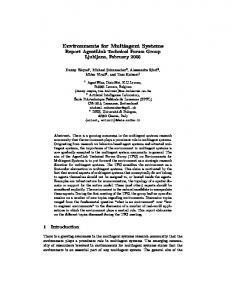
MAS application and possibly changing them during application execution. Such changes are done through organizational acts, e.g. agent actions that can modify the organization, like adding roles or changing organizational structure (PICARD et al., 2009). Figure 1.1 depicts such a MAS development issues, related to both AOSE methods and agent organizational models: they do not offer a whole software development cycle, usually only covering a sub-set of MAS components that are specified without a common meta-model.
AOSE Methods
Partial development cycle Ingenias Prometheus Gaia Tropos Partial coverage of MESSAGE ADELFE O-MaSE MASASEME components Lack of common MAS PASSI metamodel MaSE
Organization Frameworks AGR ISLANDER Lack of development method
MOISE OperA
Figure 1.1 Current development scenario for organization centered MAS
Thus, a project team that looks for a disciplined way to develop a MAS application involving such organizational characteristics will not find a method ready to be used. Nevertheless, using AOSE methods or agent organizational models separately may cause some project drawbacks. On one hand, AOSE methods offer a structured development cycle but may not support the required organizational aspects. On the other, most agent organizational models do not provide a structured MAS development cycle in terms of phases, tasks, roles1, and work products. Therefore, a project team could not take advantage of both AOSE methods and agent organizational models for developing the required MAS application. Nonetheless, without a software development method, a project is developed in an ad hoc manner. In this scenario,
1
Here we consider the notion of software development role from the Software Engineering discipline, instead of
the notion of agent role from the MAS field.
5
the project success relies on the extraordinary efforts of dedicated and well skilled individual contributors (KRUCHTEN, 2003, p. 15). Furthermore, the variety of AOSE methods suggests that historically specific needs have arisen on MAS development and that MAS developers have adopted different approaches to deal with them. This variety shows that a method cannot be general enough in order to be applied to any MAS development project without some level of customization (GUESSOUM; COSSENTINO; PAVON, 2004). An important point to notice is that this customization requires a depth of knowledge in AOSE methods and other MAS development approaches, as such agent organizational models.
1.1.2 Quality Focus in MAS Development Developing software with a focus on quality requires performing projects based on repeatable and reliable development processes, considering both the quality of delivered software and the timeliness of delivery. Development tools, methods, and processes should be built on a continuous software process improvement in order to focus on quality commitment (PRESSMAN, 2010). Roughly speaking, a software process improvement concerns understanding the development processes, including technical methods and tools, and changing them to increase product quality and reduce both development cost and time. Moreover, it is based on the assumption that the quality of the development processes is critical for both the software product quality and software development productivity (SOMMERVILLE, 2007). In resume, software process improvement consists of a cycle composed of three main stages: process measurement, analysis, and change (SOMMERVILLE, 2007, p. 667). Firstly, current quality process attributes are measured, such as process understandability and product reliability. Secondly, these measurements are assessed to identify current process strengths and weaknesses. Finally, the third stage consists of modifying
the current process in order to
mitigate its weaknesses and enforcing its strengths, such as introducing and/or eliminating artifacts, techniques, and tools, as well as changing the sequence of phases and activities. DeLoach (2009) suggests the use of repeatable, reliable, and sound agent-oriented development approaches for taking the MAS field from research into practice. Thus, a software process improvement cycle could help spread the use of MAS and AOSE in mainstream applications.
6
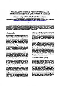
Figure 1.2 presents, from a diagrammatical perspective, a roadmap for organization centered MAS development, starting with the actual stage, i.e. the current scenario depicted in Figure 1.1, going towards a scenario in which software applications based on an agentoriented approach are developed using a sound, reliable and repeatable process. A possible intermediate scenario (shown in the lower center frame) that can be used to get to the target scenario involves bridging the current scenario gap, by creating a whole MAS development cycle, taking into account both project phases and MAS components, possibly founded into a set of common MAS concepts. Finally, the target scenario depicted in Figure 1.2 (upper right) involves the development of MAS applications based on an improvement cycle for MAS development methods. Such a cycle involves analyzing MAS project issues, changing MAS development methods based on such analysis, and then executing and measuring the MAS project. Besides, this cycle is based on those proposed by Sommerville (2007) and Basili (1993) dealing with software engineering in general, presented in Chapter 2. Current Scenario AOSE Methods Ingenias
Prometheus
Lack of common MAS MESSAGE ADELFE metamodel
Target Scenario
Partial development cycle Gaia Tropos Partial coverage of O-MaSE MAS components PASSI ASEME MaSE
Organizational Models AGR ISLANDER Lack of development method
MOISE
Executing & Measuring MAS projects
Organization Centered Multiagent System development
Changing MAS development methods
Analyzing MAS projects issues
OperA
Intermediate Scenario MAS Analysis User Requirements
MAS Design
MAS Implementation
MAS Testing
MAS Deployment
Agent Component Environment Component Interaction Component Organization Component
Figure 1.2 Three development scenarios for organization centered MAS: from current to target
This dissertation contributes in two ways to achieve this target scenario for organization centered MAS development. Firstly, it proposes a method framework for composing MAS methods that may cover main MAS development phases and components.
7
Secondly, this dissertation proposes an improvement cycle for organization centered MAS development methods.
1.2 Research Questions Considering, on one hand, that this thesis is concerned with the development of organization centered MAS based on a disciplined way to perform the software project and, on the other, the current MAS development issues presented in the previous section, the main research questions that have guided this work are presented below:
1) How to combine the broad knowledge related to AOSE methods and agent organizational models in order to create methods for promoting development of organization centered MAS in a disciplined way, taking advantage of the research from both fields?
2) Is it possible to focus on quality to promote a software improvement cycle for developing organization centered MAS? If so, how to measure,
analyze,
and change the development methods involved in such a cycle?
3) Can such development methods and improvement cycle be effectively used for building organization centered MAS applications?
This thesis looks to answer these three questions, as presented in the course of this text.
1.3 Research Approach In this thesis we investigate the development of organization centered MAS through projects performed in a disciplined way, even using agent organizational models that are not incorporated to AOSE methods. Thus, this thesis proposes a systematic way to compose and improve methods for developing this class of applications. The current MAS development scenario presented in Section 1.1.1 - the variety of AOSE methods and agent organizational models and their related issues - suggests that Situational Method Engineering (BRINKKEMPER, 1996; HARMSEN, 1997) could be a promising approach to be considered for organization centered MAS development. Indeed, the approach
8
adopted in this doctoral dissertation is strongly based on the principles of Situational Method Engineering. Thus, before presenting this research objective, the next section outlines the mains aspects of such a discipline.
1.3.1 Situational Method Engineering Situational Method Engineering is a sub-division of Method Engineering where development methods are tailored for a given situation. Roughly speaking, a situational method is built from reusable parts of methods according to a project situation. It is constructed in a controlled and computer-assisted way. This type of project situation encompasses several factors, for example, those related to the project team, such as size, levels of experience, as well as those relating to the problem at hand, to the product to be engineered, and available project resources. Kruchten (2003, p.30) suggests that a development method should not be used before being customized according to current project characteristics. Otherwise, the project risks wasting work already done and producing artifacts of little added value. On one hand, the method might be made as lean as possible and, on the other, it must fulfill the objective to produce high quality software. A suitable method for a small project, for example a three month project, typically will not fit a larger project, such as a three year project, given that during a longer time period, the project environment – such as the problem to be solved and people involved - will probably change. Several approaches to compose situational methods have been proposed in Situational Method Engineering, among them the method fragment (BRINKKEMPER, 1996, HARMSEN, 1997).
Such an approach supports the specification of method fragments into several layers of
granularity and a mechanism for composing situational methods, by assembling the selected fragments.
1.3.2 Research Objective This thesis aims to cover two major steps towards the target organization centered MAS development scenario presented in Figure 1.2. On one hand, this thesis proposes composing MAS situational methods out of
method fragments sourced from both AOSE
methods and agent organizational models in order to cover several development phases and MAS components according to a specific project situation. Such an approach applies the principles proposed by Situational Method Engineering, which allow tailoring methods even
9
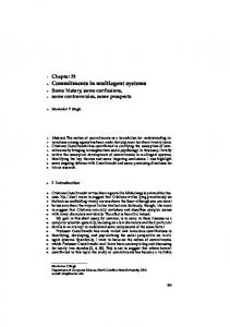
though AOSE methods and agent organizational models involve distinct MAS meta-models and concepts. On the other hand, this thesis proposes embedding organization centered MAS development in an improvement cycle, focusing on the continuous enhancement of MAS development methods. Such a cycle applies Software Engineering principles for measuring, analyzing, and changing the MAS situational methods. Figure 1.3 depicts the main aspects of the objective of this thesis. Firstly, the proposed solution allows a method engineer to elaborate a collection of method fragments sourced from several AOSE methods and agent organizational models, as well as to store them in a Method Repository. Such a repository could then cover most development phases and MAS components, depending on the AOSE methods and agent organizational models used as method fragment sources.
Method Fragment Elaboration
AOSE Methods
MAS Method Fragments
F1
Organizational Models
F4 F5 F1
F2
F4 F3 F5
F2
F3
Method Engineer Method Repository MAS Project Analysis
MAS Project Measurement
Agent
MAS Project Execution
Org MAS
Project Situation
Situational Method Composition
MAS Situational Method
Project Team Method Engineer
Figure 1.3: Research objectives in a diagrammatical perspective
Secondly, we propose an approach that allows a method engineer selecting the suitable method fragments according to a specific project, and composing a MAS situational method
10
out of such fragments. In such an activity, the method engineer can eventually be helped by some members of the project team. Thirdly, the proposed solution allows the project team, including the method engineer, to measure and analyze several quality attributes of the MAS situational method during the project execution, such as the extent in which the situational method addresses the factors that characterize the project situation and how easy it is to be understood. Finally, closing the improvement cycle, the lessons learned resulting from MAS project analysis could then be used by the method engineer to enhance the content of the Method Repository. To the best of our knowledge, there is no research concerning MAS situational methods for building organization centered MAS as part of an improvement cycle for MAS development.
1.3.3 Research Procedure These research objectives have been achieved by taking the following steps: 1. Definition of building blocks for composing situational methods for organization centered MAS out of method fragments. Such building blocks include Medee MAS method fragments, Medee MAS situational methods, and a situational composition model that guides the creation of MAS situational method according to a specific project situation, called Medee Composition Model. 2. Development of a MAS method repository to store both method fragments and situational methods, called Medee Method Repository. 3. Development of a procedure to populate the Medee Method Repository with MAS method fragments captured
from
AOSE methods and agent organizational
models, as well as composing situational methods out of these fragments. Such a procedure is called Medee Delivery Process. 4. Population of the MAS method repository with method fragments sourced from several AOSE methods and agent organizational models. Namely, Tropos, Gaia, PASSI, Ingenias, MOISE+, and OperA. 5. Proposition of an improvement cycle for the Medee MAS situational methods, the Medee Improvement Cycle.
11
6. Design a case study to investigate the use of the proposed solution for developing organization centered MAS projects in a disciplined way, as part of an improvement cycle for MAS methods.
Figure 1.4 depicts such a research approach from a diagrammatical perspective, showing that the definition of Medee building blocks, together with the Medee Method Repository and Medee Delivery Process contribute to achieving the intermediate scenario for developing organization centered MAS, presented in Section 1.1.2.
Medee Framework Towards MAS Development Ideal Scenario
Medee Improvement Cycle
Steps 5 and 6 Medee Delivery Process MAS Development Intermediate Scenario Steps 1, 2, 3 and 4
Medee Repository Medee Building Blocks
Figure 1.4: Main components of the research approach
Furthermore, Figure 1.4 shows that the Medee Improvement Cycle, built upon the previous propositions, contributes to reaching the ideal scenario for organization centered MAS development. Finally, as depicted at the top of Figure 1.4, all these elements – Medee building blocks, Medee Method Repository, Medee Delivery Process, and Medee Improvement Cycle – constitute the Medee Framework that is the main contribution of this thesis.
12
1.4 Text Structure This doctoral dissertation consists of three parts, containing nine chapters, and three appendixes. Figure 1.5 depicts how these parts and the relating chapters are structured according to the research procedure previously presented. Part I, which is composed of Chapters 2, 3 and 4, presents background and related work concerned with the research approach. While Chapter 2 focuses on aspects of Software Engineering that are related to the subject of this thesis, namely, software development methods and quality improvement cycle, Chapter 3 presents the main aspects of the MAS field, highlighting those closely relating to the subject of this dissertation, namely, AOSE methods and agent organizational models. Furthermore, Chapter 4 focuses on aspects of the Situational Method Engineering discipline, including concepts, meta-models, frameworks, and tools.
Part II: The Medee Framework
Chapter 6
Medee Improvement Cycle
Chapter 4 Chapter 3 Chapter 2
Chapter 8
Medee Delivery Process Medee Repository
Part I: Background and Related Work
Part III: Application of Medee Framework
Medee Framework
Chapter 5
Chapter 7
Medee Building Blocks
Situational Method Engineering Multiagent Systems Development Software Engineering
Figure 1.5: Dissertation Structure
Part II, which is composed of Chapters 5 and 6, describes the proposed solution itself, namely, the Medee Framework. Chapter 5 presents the main building blocks for developing organization centered MAS applications in a disciplined way. They are: Medee MAS Method Fragment, Medee MAS Situational Method, and Medee Composition Model. Chapter 6 shows
13
how to compose and improve methods for developing this class of MAS applications, using the Medee Framework. Part III, which is composed of Chapters 7, 8, and 9, describes the applications of the Medee Framework. Firstly, Chapter 7 shows how the Medee Framework can be populated with method fragments sourced from several MAS development approaches. Secondly, Chapter 8 presents a case study conducted to investigate the use of the Medee Framework for composing MAS situational methods, sourced mainly from Tropos, Gaia, and MOISE+. Moreover, these situational methods were used within an improvement cycle for MAS development methods. This case study, called the USP Farmer project, involved the development of organization centered MAS to solve the problem proposed by the Multiagent Programming Contest.
Chapter 9 presents our conclusions, highlighting the main
contributions of this work as well as some directions for future work. Finally, Appendix A complements the description of the Medee Framework population presented in Chapter 7, showing how it can be populated with method fragments sourced from MAS development approaches not involved in the USP Farmer project, while Appendix B presents the questionnaires used to collect data during this case study. Appendix C presents how to access the CD recording of the contributions of this research project.
14
Part I Background and Related Work
15
Chapter 2 Software Engineering This chapter presents the main aspects of the engineering discipline concerned with software production, namely Software Engineering. Although the huge amount of literature concerning this discipline, both in the industry and academic arenas, this chapter focuses on aspects of Software Engineering that are related to the subject of this dissertation, more precisely, software development methods and quality improvement cycle. It is set out as follows: Section 2.1 outlines the main concepts of Software Engineering, while Section 2.2 and 2.3 detail software quality and development methods respectively. Finally, Section 2.4 discusses some of the issues relating to these aspects.
2.1 Introduction The Institute of Electrical and Electronics Engineers (IEEE, 1990, p. 67) defines Software Engineering as the study and “application of a systematic, disciplined, quantifiable approach to the development, operation, and maintenance of software; that is, the application of engineering to software”. In other words, Software Engineering is an Engineering discipline concerned with the practical problems of producing software, from the early phases of system specification to maintaining the system after deployment. As an Engineering discipline, Software Engineering concerns the application of theories, methods and tools where appropriate, taking into account organizational and financial constraints. Along with the technical processes of software development, Software Engineering is about the development of tools to support software production, as well as software project management (SOMMERVILLE, 2007). Thus, the main Software Engineering goal is to provide processes, methods, techniques, models, and tools to cope with the complexity inherent to the software development (SOMMERVILLE, 2007). Such Software Engineering aspects can be grouped into four layers – Quality Focus, Processes, Methods, and Tools - as depicted in Figure 2.1 (PRESSMAN, 2010, p.14). While the
16
first two layers are based on traditional engineering1 procedures, the remainder is more dependent on software technology aspects (PRESSMAN, 2010). This dissertation is concerned with two of these four layers -
Quality Focus and
Methods layers – since it proposes a method framework for developing organization centered MAS towards a continuous method quality improvement. Thus, the following paragraphs outline these four layers, while the next sections present the main conceptual aspects concerning quality focus and software development methods. A quality focus is the basic principle that supports Software Engineering since, as an Engineering discipline, it deals with the commitment to quality, fostering a continuous process improvement culture that leads to the development of more effective approaches to building software.
Tools Methods Processes Quality Focus Figure 2.1: Four Software Engineering layers (PRESSMAN, 2010, p.14)
Furthermore, the Processes layer aims to establish rational and timely software development, constituting the basis for management control of software projects. In resume, project management deals with planning, scheduling, managing risks, and controlling resources and costs. Sommerville (2007, p.93) points out that project management is an essential part of Software Engineering, since it aims to ensure that software projects meet their constraints, such as deadline, budget, and product quality. Moreover, he suggests that although good project management cannot assure project success, bad management usually causes project failure independently of the other three layers.
1
Engineering concerns the “application of a systematic, disciplined, quantifiable approach to structures,
machines, products, systems, or processes” (IEEE, 1990, p. 30).
17
The next layer - the Methods layer - is concerned with technical development methods for building software. Such methods are composed of development phases - such as requirements, analysis, design, implementation, test, and deployment- over the course of which all the artifacts encompassed in a software system are produced, like models, diagrams, source code, and machine executable code.
Without a software development method, a
software project is developed in an ad hoc manner. As previously mentioned, the success of a project relies on the extraordinary efforts of dedicated and well skilled individuals whenever executed in an ad hoc way. Given that it is not sustainable, software organizations should use a well-defined method to develop software systems in a repeatable and predictable way (KRUCHTEN, 2003, p.16). Finally, the Tools layer offers support for the three previous layers. A tool is a means, that can be automated or semi automated and used to support part of the software development process (BRINKKEMPER, 1996). Such tools, commonly called computer-aided software engineering (CASE) tools, encompass a broad range of computer programs that can be classified into three perspectives: (i) a
functional perspective that groups CASE tools by functionality; (ii) a process
perspective that takes into account the development phase in which tools are involved (e.g. requirements, analysis, design); and (iii) an integration perspective that aims to group tools taking into account how they are put together in integrated units that provide support for process and method activities (SOMMERVILLE, 2007). From a functional perspective, CASE tools can be classified using the following categories (SOMMERVILLE, 2007), among others: •
planning tools: for project estimations and scheduling, such as PERT1 tools;
•
change management tools: such as change control systems and requirement traceability tools;
•
configuration management tools: such as version management system and system building tools;
•
method-support tools: such as Unified Model Language (UML) (BOOCH; RUMBAUGH; JACOBSON, 1999) based
1
tools for graphical analysis and design;
PERT stands for Program Evaluation and Review Technique. It consists of a project management technique for
showing time taken for each project task, activity, phase, and so on.
18
•
language-processing tools: such as compilers and interpreter tools;
•
program analysis tools: such as cross reference generators and static analyzer tools;
•
testing tools: such as test data generators;
•
debugging tools: such as interactive debugging systems;
•
re-engineering tools: such as program restructuring systems.
As previously mentioned, the next sections describe two of the Software Engineering layers in detail: the software quality focus and methods layers.
2.2 Software Quality Focus 2.2.1 Overview The software quality focus layer aims to guide the development processes towards being more focused, repeatable, and reliable, considering both quality of the delivered software application and timeliness of delivery. Although the use of processes, methods, and tools is essential to the development of software, ensuring that a software project meets its requirements while exhibiting the technical characteristics and being executed on the scheduled period of time is not enough. Thus, such tools, methods, and processes should be built upon a continuous software process improvement in order to focus on quality commitment (PRESSMAN, 2010). In brief, software process improvement means understanding existing development processes including: managerial control, technical methods and tools, and changing them to increase product quality, reduce development costs and time (SOMMERVILLE, 2007). Hence, software process improvements should decrease the number of defects in the software product delivered to end users, as well as the amount of rework needed due to poor product quality, and consequently leading to cost reduction in software development, maintenance, and support (PRESSMAN, 2010). Furthermore, process improvement is based on the assumption that the quality of the development processes (and methods) affects, and is critical, to both the software product quality and software development productivity. However, such quality and productivity are also affected by other factors, like aptitude, ability, and experience of the team members in the application domain, as well as project size (the larger the project the more time is required
19
for team communication and less time is available for programming). Finally, such factors also involve development tools and working environment (SOMMERVILLE, 2007). The following steps are suggested by Humphrey (1988) to improve the quality of a software process: (i) understanding the current software development process; (ii) developing a vision of the desired process improvement; (iii) defining the actions that are required to achieve the process improvement; (iv) establishing a plan to carry on these actions; and (v) committing resources to execute this plan. Moreover, Humphrey (1988) claims that by addressing the software production issues, the adopted process should be continually controlled, measured, and improved. In a similar way, Sommerville (2007) suggests that software process improvement consists of a cycle composed of three main stages - Process Measurement, Process Analysis, and Process Change – as shown in Figure 2.2 (SOMMERVILLE, 2007, p. 667).
Measure
Change
Analyze
Figure 2.2: The Process Improvement Cycle (SOMMERVILLE, 2007)
As its name indicates, the Process Measurement stage deals with the measurement of current process quality attributes, as well as those attributes that characterize the (software) product generated during project execution. Measuring an attribute consists of assigning a value to it using specific metrics. A metric usually includes a scale of values (e.g. 1, 2, 3) and a value domain (e.g. poor, medium, excellent) (MENDONÇA; BASILI, 2000). The choice of which quality attributes to be measured should reflect the desired measurement goals. For instance, such goals could be related both to how understandable the process is and to process reliability, as described in Chapter 8. The next stage, Process Analysis, consists of assessing project measures in order to identify process strengths and weaknesses, as well as to determine software product
20
limitations. To be effective, a process analysis should take into account the organizational context and project environment, along with collected measures (BASILI; CALDIERA, ROMBACH, 1994).
Finally, the Process Change stage consists of applying appropriate modifications into the current process to mitigate its weaknesses and limitations, as well as enforcing its strengths. These modifications could consist of introducing or eliminating tasks, techniques, and tools, changing the sequence of phases and activities, introducing or eliminating work products, or introducing new development roles and responsibilities. Several frameworks for dealing with such stages of process improvement have been proposed in the Software Engineering field over the last decades. These frameworks are commonly used in the software industry to assess the maturity level of an organization’s software process and to provide a qualitative indication of such a level, like the following scale of the process maturity level (HUMPHREY, 1988): initial process (ad hoc process), repeatable process (provides basic management control), defined process (offers process definition), managed process (involves process measurement), and optimized process (involves process control). The Standard Capability Maturity Model Integration Assessment Method for Process Improvement (SCAMPI) (SEI, 2001), as proposed by the Software Engineering Institute1 (SEI), and the Software Process Improvement and Capability Determination (SPICE)2 are among these frameworks. Moreover, less formal process improvement frameworks have been proposed, such as the Quality Improvement Process (QIP) (BASILI; SELBY; 1991; BASILI, 1993), and the Goal Question Metric Paradigm (GQM) (BASILI; WEISS, 1984; BASILI; CALDIERA; ROMBACH, 1994). The following sections describe the QIP and GQM process improvement frameworks in detail since they have provided the backbone for defining the Medee Improvement Cycle, presented in Chapter 6.
1
The Carnegie Mellon Software Engineering Institute (SEI) was created in 1984. Its mission is to advance software
engineering and related disciplines to ensure the development of software systems with improved quality, cost predictability and scheduling. For more information, see 2
SPICE is an international initiative to support the development of an international standard for Software
Process Assessment. The first version of this standard was released in 1995. For more information, see
21
2.2.2 Quality Improvement Paradigm The Quality Improvement Paradigm (BASILI; ROMBACH, 1988; BASILI; SELBY, 1991; BASILI, 1993) is
an evolutionary software quality process that aims to provide a mechanism for
software improvement through experimentation and reuse of project experience. Such a paradigm proposes to treat software development as empirical experiments in order to learn with them and thus improve the way to build software. QIP is based on the following assumption: before determining which software development method should be applied, the current project must be characterized, as well as improvement targets must be set. Such characterization helps tailor the development method. As shown in Figure 2.3, this paradigm involves six steps: (i) characterization of the current project and its environment; (ii) setting the measurement goals for project analysis; (iii) choosing the project process and method; (iv) executing the project and collecting analysis data; (v) analyzing the collected data; and finally (vi) packaging the project experience.
1. Characterizing the current project and its environment considering People, Problem, Process, Product, and Resource factors. 2. Setting the measurement goals for the project
3. Choosing the project process and method
4. Executing the project and collecting data
5. Analyzing the collected data 6. Packaging the project experience for future use
Figure 2.3: QIP six steps
2.2.2.1 Characterization of the Current Project and its Environment The first step - Characterization of the current project and its environment - consists of analyzing the project situation to identify the relevant factors for project development. Given
22
that each project has a particular situation, in some way distinct from other projects, such a project situation should be made explicit and taken into account during the definition of the project (measurement) goals, the choice of the appropriate development method, and the project execution itself (BASILI; ROMBACH, 1988). Thus, project characterization aims to define the project situation in an explicit way according to the following dimensions: people, problem, product, process/method, and resources (BASILI, 1981, 1993). People factors relate to project team characteristics, like team size, team organization, levels of expertise of team members, as well as motivation, ability to communicate, previous experience with the problem domain and the target development method. Factors relating to the problem to be solved by the software product include problem type (as mathematical, database manipulation), problem magnitude (as big, medium, small), state of the problem definition (as informal or formal specification), susceptibility of the problem to change, importance of the problem and how new it is compared to current state-ofthe-art. Product related factors encompass those relating to the software product itself. They include the number of expected deliverables, e.g. artifacts delivered at the end of the project, product size in lines of code, product structure, such as number of components or subsystems, and non-functional product aspects, such as portability, reliability, and maintainability. Factors relating to process and method have several aspects, among them (i) the development life cycle model (e.g. waterfall, iterative), (ii) the adopted software paradigm, such as structured programming, object-oriented, agent-oriented development, and (iii) the programming language (e.g. Java, C). Finally, resource related factors are those to do with nonhuman elements of software development such as the project budget, the project deadline, the set of development tools, as well as the computer infrastructure, such as the target machine system and the development machine system. It is worth while noticing that there is a strong relationship between resource and product factors, since resources define limits for product performance. 2.2.2.2 Setting the Measurement Goals for Project Analysis The second step consists of establishing quantifiable goals for the current project according to the project improvement targets, as well as the mechanism to measure such goals. Thus, a measurement goal can be related to the process, the method, or the artifacts
23
generated during the project. Furthermore, a measurement goal can take several points of view into account, like the end user, project manager, or developer. Examples of measurement goals are: (i) to promote method acceptability by developers to ensure it is actually followed, and (ii) to improve method visibility by emphasizing results generated for each activity to clearly show the progress of the project. The Goal Question Metric Paradigm (BASILI; WEISS, 1984, BASILI; CALDIERA; ROMBACH, 1994)
is one of the measurement approaches that can be used in this step. Section
2.2.3 provides an overview of this paradigm. 2.2.2.3 Choosing the Project Process and Method The third step consists of choosing and tailoring the process and method for the current project. Both of them should be tailored before being used, given that each project has particular characteristics, as previously described. Thus, this step encompasses the choice of the most appropriate process and method, as well as tailoring them to deal with the project factors
better, relating to people, problems, products, process, and resources (BASILI;
ROMBACH, 1988).
It is worth noting that method tailoring is the subject of a specific engineering discipline, called Situational Method Engineering (BRINKKEMPER, 1996, HARMSEN, 1997), presented in detail in Chapter 4. 2.2.2.4 Executing the Project and Collecting Analysis Data The fourth step consists of running the project, according to the tailored process and method, to produce the required software products. Furthermore, this step involves collecting data that will be used to analyze measurement goals already established (see second step). Additionally, this data should be validated during project execution to allow for corrective real-time actions, if necessary. Some examples of data collected during project execution are: process related data (e.g. process conformance), product data (e.g. size and complexity), and resource data (e.g. required effort by activity and calendar time). 2.2.2.5 Analyzing the Collected Data The fifth step consists of interpreting the data collected during project execution, based on project goals. Such analysis aims to understand and evaluate the project process and method, as well as to produce project findings and recommendations for project improvement.
24
2.2.2.6 Packaging the Project Experience Finally, packaging the project experience involves organizing and storing the experience acquired during the previous steps as a structured knowledge, in such a way that it can be used for future projects. It consists of a project data analysis done after the project end, called a post-mortem analysis, which does not allow feedbacks during the own project execution.
2.2.3 Goal Question Metric Paradigm The Goal Question Metric paradigm (BASILI; WEISS, 1984, BASILI, 1992, BASILI; CALDIERA; ROMBACH, 1994)
consists of a popular approach for defining and evaluating
measurement goals. It was originally developed for NASA at the Goddard Space Flight Center to evaluate software defects, and later used to create and establish measurement programs throughout several organizations, such as HP, AT&T, and IBM (BASILI et al., 2007). As its name indicates, GQM encompasses three main notions: measurement goal, questions of interest, and metrics. Thus, this paradigm involves identifying a set of measurement goals related to the project improvement targets, questions of interest used to refine these goals, and metrics that should be collected to answer these questions to discover whether the measurement goals have been achieved or not. Therefore, questions of interest provide a bridge between the measurement goals subjectively defined at a high level, and the metric to be collected, by forcing sharper definition of measurement goals to guide data collection and data analysis (BASILI; WEISS, 1984). It should be mentioned that the GQM paradigm does not provide a specific measurement model composed of a set of particular measurement goals, questions and metrics. Rather, it offers an abstract structure and a procedure for stating measurement goals and refining them into questions of interest about the object to be measured (BASILI; ROMBACH, 1987).
An example of such a structure is depicted in Figure 2.4 (BASILI, 1992), including three goals (Goal 1 to 3), four questions of interest (Question 1 to 4), and six metrics (Metric 1 to 6). As shown in this figure, distinct goals can share questions, as well as questions can share metrics. For instance, Goal 2, related to project productivity, and Goal 3, related to product maintainability, are refined through Question 3 (What is the complexity of the product?) Such a question is answered by Metric 4 (number of lines of code) which is also used to answer Question 2 (What is the product size?) (BASILI, 1992).
25
Goal 1
Question 1
Metric 1
Metric 2
Goal 2
Question 2
Metric 3
Goal 3
Question 3
Metric 4
Question 4
Metric 5
Metric 6
Figure 2.4: An abstract GQM structure composed of goals, questions and metric (BASILI, 1992)
In order to guide the definition of measurement goals, Basili and colleagues (BASILI; CALDIERA; ROMBACH, 1994, MENDONÇA; BASILI, 2000)
suggest a goal template involving four
concepts - object of study, purpose, issue, and viewpoint entity – as follows: Analyze “object of study” in order to “purpose” with respect to “issue” from the point of view of “viewpoint entity” In such a template, an object of study specifies the target of the goal, as product, process, method, or resource, while purpose defines the reason for the measurement goal. Main reasons are characterization, evaluation, prediction, and motivation. For instance, (i) characterization purpose may help distinguishing the process and method aspects, such as tracking the process schedule, providing information on where the project stands with respect to aspects such as percent of resource use and calendar time; (ii) evaluation purpose may be used for assessing the quality of a given development method, such as showing the work productivity; (iii) prediction purpose may refer to predicting and estimating some information at later point in time; and (iv) motivation purpose can be used for letting the project team know what is important in a quantitative way. An issue defines the measurement goal focus. Examples of issues are cost, correctness, robustness, maintainability, and reliability. Finally, viewpoint entity defines a particular angle for the measurement. For instance: developers, project managers, customer, and a software corporation. An example of a measurement goal using this template is: Analyze the AOSE method for the purpose of evaluation with respect to the understandability from the point of view of the
developer. Chapter 8 presents a GQM model used in the case study conducted to investigate the Medee Framework, involving several measurement goals, questions, and metrics.
26
The next section presents the main concepts related to the third layer encompassed by the Software Engineering discipline - the Methods layer – describing, among other concepts, a set of method attributes adopted in the Medee Improvement Cycle, presented in Chapter 6.
2.3 Software Development Method 2.3.1 Main notions Brinkkemper (1996) suggests that there are four notions strongly related to software development methods: method, methodology, technique, and tool. Given that a definition of tool has been presented in the previous section, this section presents the three first notions, starting with the central one: the method notion. Among several definitions available for Method and its related notions, this dissertation adopts those proposed by Brinkkemper (1996). 2.3.1.1 Method The word ‘method’ comes from a Greek word - methodos - which means ‘way of investigation’. Roughly speaking, a software development method encompasses a set of integrated procedures, techniques, and product descriptions, which provides a consistent support for the software development (HARMSEN, 1997). According to Brinkkemper (1996): A method consists of an approach to perform a systems development project. It is based on a specific way of thinking and involves directions and rules that are structured in a systematic way in development activities with corresponding products. Methods give the stepwise structuring of the development activities and the requirements for the products, also called work products or deliverables (BRINKKEMPER, 1996, p. 275).
This dissertation extends the previous definition to encompass the notion of a development role, as proposed by the Object Management Group (OMG, 2008a) and Kruchten (2003), among others. Such a role consists of a set of skills, competencies, and responsibilities of an individual or a group of individuals working together as a team (KRUCHTEN, 2003, p. 36; OMG, 2008a, p. 87).
Thus, in this thesis,
27
A software development method consists of a disciplined approach to perform a software project. It involves work directions and rules that are structured into phases, iterations, activities, and tasks. Such a structured work is associated to the corresponding work product and the required development roles. A software development method typically includes activities relating to requirements, analysis, design, implementation, and test (JACOBSON; BOOCH; RUMBAUGH, 1999). A requirement is a capability or condition that must be met by a system (IEEE, 1990, p. 62). Thus, requirements activities consist of identifying, organizing, and documenting the set of capabilities that the users expect that the software will provide to solve their problem or achieve their objectives. In brief, such activities concern identifying and clearly stating the system’s required functionalities and constraints (KRUCHTEN, 2003, p. 9). Analysis activities consist of analyzing these requirements to outline the system that will provide a solution for the stated problem, usually through a system conceptual model. Next, design activities consist of developing system architecture in terms of subsystems, components, and so on, as well as refining the conceptual model to create a blueprint for system implementation. Implementation activities are concerned with constructing the designed system, by producing source code, scripts, executables, and so on. Finally, test activities consist of verifying and validating the implemented programs and/or components by testing them. Such activities are grouped together to form development phases. In some cases, such development phases are designated through the same name as the activities, like requirements, analysis, and design phases (ZAMBONELLI; JENNINGS; WOOLDRIDGE, 2003; BRESCIANI et al., 2004, SPANOUDAKIS, 2009).
In other cases, these activities are grouped into iterative phases
such as inception, elaboration, and construction phases (JACOBSON; BOOCH; RUMBAUGH, 1999; KRUCHTEN, 2003, BERNON et al., 2002; PAVON; GOMEZ-SANZ; FUENTES, 2005).
2.3.1.2 Methodology According to Brinkkemper (1996, p. 276), a methodology “is the systematic description, explanation, and evaluation of all aspects of methodical information systems development”. Such a definition restricts the meaning of methodology to the scientific principles concerning methodical development of informational systems. In other words, methodology is about the study of methods, while method is about how a project is executed. Nonetheless,
28
Harmsen (1997) points out that several authors tend to use the term methodology1 standing for method. Brinkkemper (1996) suggests that such a misuse is a sign of the immaturity of the Method Engineering field, and strongly recommends the adoption of method, instead of methodology. 2.3.1.3 Technique A technique consists of a procedure to perform a development activity. It can involve a prescribed notation, such as a graphical or a mathematical notation. However,
a technique
is more than a specific notation, since it also encompasses a procedural aspect. An example of a technique is where interviewing system users use natural language to gather system requirements, and produce data modeling using entity-relationship diagrams to outline the data base of the system-to-be (BRINKKEMPER, 1996).
2.3.2 Methods Overview Several methods have been proposed for software development over the last decades, commonly associated with distinct software development paradigms, such as the structured design2, the object-oriented and agent-oriented paradigms. Structured Analysis / Structured Design (SA/SD) (DEMARCO, 1979), and Yourdon’s Structured Analysis (YOURDON, 1989) are among those methods related to the structured programming paradigm, while Unified Software Development Method (USDP) (JACOBSON; BOOCH;
RUMBAUGH, 1999),
Rational Unified Process (RUP) (KRUCHTEN, 2003), Extreme
Programming (XP) (BECK, 2000), and Scrum (SCHWABER; BEEDLE, 2002) are among those methods related to the object-oriented paradigm. Some of these methods, such as RUP, XP, and Scrum, offer activities related to project management control along with the technical development activities. Gaia (ZAMBONELLI; JENNINGS; WOOLDRIDGE, 2003), Prometheus (PADGHAM; WINIKOFF, 2002),
Tropos (BRESCIANI et al., 2004), MaSE (WOOD; DELOACH, 2001), PASSI
(COSSENTINO, 2005), ADELFE (BERNON et al., 2002), Ingenias (PAVON; GOMEZ-SANZ;
1
The term methodology usually stands for method in the AOSE field. For instance, Gaia, PASSI, and Tropos are
presented as methodologies for agent oriented software development, instead of methods. 2
Structured design consists of an approach to software design that adopts principles such as modularity and top-
down design in order to deal with system structures and data.
29
FUENTES, 2005),
and ASEME (SPANOUDAKIS; MORAITIS, 2010) are among the development
methods related to the agent-oriented paradigm. These methods are described in Chapter 3, which details the Agent-Oriented Software Engineering (AOSE) (JENNINGS; WOOLDRIDGE, 1999).
However, no single method can be applied universally. Instead, methods should be tailored to fit each specific project situation, according to: type of software system to be built up, target schedule and cost, required software reliability, quality, and so on (JACOBSON, BOOCH, RUMBAUGH, 1999, p. 26).
Method tailoring is usually taken into account by the Quality
focus layer, as it was commented on in Section 2.2. Furthermore, as mentioned in the introduction of this dissertation, Situational Method Engineering is the discipline that deals with method tailoring, and is presented in more detail in Chapter 4. Given that USDP and RUP constitute the roots of some AOSE methods - such as Ingenias, ADELFE, and PASSI - the next two sections outline the main aspects of these two object-oriented methods. Moreover, a detailed description of the USDP requirements activities is presented in Chapter 7, since this method is among those used to populate the Medee Method Framework.
2.3.3 Unified Software Development Process (USDP) As its name suggests, the Unified Software Development Process (JACOBSON; BOOCH; RUMBAUGH, 1999)
proposes an unified vision of distinct object-oriented development
approaches: Object Modeling Technique (OMT) (RUMBAUGH et al., 1991), Object Oriented Software Engineering (OOSE) (JACOBSON, 1992), and the Booch Method (BOOCH, 2004). USDP is characterized in three main aspects. Firstly, it is use case driven, in the sense that system requirements, as stated through a set of use cases1, drive project development activities.
Secondly, it is architecture-centric, since the software architecture concept
encompasses both static and dynamic aspects of the system. It also provides a system architecture which is understandable for the whole project team, resilient to future changes, and reusable in other project contexts. Thirdly, it offers an incremental and iterative way to build software. The whole project is divided into several smaller sub-projects, called project iterations, and the execution
1
Use case is a UML concept that represents the required behavior of a system according to the needs of its actors
(OMG, 2007).
30
of each one of these iterations produces a project increment. Together, the product increments form the software product that results from the whole project. Moreover, USDP proposes four development phases: Inception, Elaboration, Construction, and Transition. While the Inception phase aims to define the project objective, Elaboration phase establishes the architectural baseline that can evolve during one or more iterations. Next, the Construction phase leads to the initial operational capabilities of the system through the implementation of the system’s main functionalities, often called betatesting. Usually, this phase embodies several iterations, each one of them delivering a system increment. Finally, the Transition phase completes the product release, focusing on establishing the software system in the operational environment, and modifying the system according to feedback received from users. Along with these four phases, the USDP proposes five core workflows that group activities and work products according to goals within the project lifecycle: requirements, analysis, design, implementation, and test. Such core workflows, also called disciplines, take place over the four phases in distinct degrees. For instance, most activities and work products relating to analysis are carried out during the Elaboration phase, while most of those relating to implementation occur during the Construction phase. Finally, USDP uses the UML as the graphical language to specify, document, and communicate the main aspects of software artifacts over the course of the development phases and core disciplines.
2.3.4 Rational Unified Process (RUP) The Rational Unified Process (KRUCHTEN, 2003) shares the same main characteristics with USDP: it is use case driven, proposes an architecture-centric development process, and involves iterative work cycle to produce incremental products. Furthermore, it is strongly based on UML and proposes the four USDP phases, among others. Indeed, RUP offers a kind of a USDP “trademark flavor”, given that it is available only under license1. However, RUP proposes a broader scope than USDP, since it covers both the technical aspects and managerial control of a software development project. This way, RUP covers two of the four Software Engineering layers proposed by Pressman (2010) - Methods and Processes layers – while USDP covers only the Methods layer. 1
RUP was originally developed and marketed by Rational Software, and later by IBM. See for more information.
31
Figure 2.5 (KRUCHTEN, 2003, p. 22) shows the RUP phases, iterations, and disciplines structured into two dimensions: time on the horizontal axis, and process content on the vertical axis. The first dimension (horizontal axis) represents the dynamic aspect of the process in terms of the phases and iterations that take place during the project execution inception, elaboration, construction, and transition phases - and their corresponding iterations. The second dimension (vertical axis) represents the static aspect of the process, composed of the nine disciplines that group RUP activities by nature: business modeling, requirements, analysis and design, implementation, test, deployment, configuration and change management, project management, and environment. Some of these disciplines deal with the technical aspect of the project and are similar to those proposed by USDP, while other deal with business and managerial control aspects.
Figure 2.5: RUP bi-dimensional representation (KRUCHTEN, 2003)
The goal of business modeling discipline is to describe the structure and dynamics of the organization in which the software system is to be deployed. Such a description involves business processes, roles, and responsibilities of that organization.
Project management
discipline embodies the activities to monitor and control the project budget, risk, schedule, and so on. The purpose of the configuration and change management discipline is to control and maintain versions and integrity of the work products produced during the project iterations.
32
Finally, environment discipline deals with the process tailoring and the tools selection according to the project needs. This discipline aims to keep the process up to date during the whole project lifecycle, reflecting environmental changes - such as problem, product, and resources factors - into the process itself. As shown in Figure 2.5, activities relating to this discipline take place mainly at the beginning of each phase. It is worthy noting that RUP and USDP are usually designated only as Unified Process by the Software Engineering community.
2.3.5 Method Quality Attributes Like software products, software processes and methods can be characterized by a set of quality attributes. Furthermore, such attributes may be used to drive method quality improvement. Sommerville (2007) proposes the following attributes to characterize processes and methods: understandability, visibility, supportability, acceptability, reliability, robustness, rapidity, and maintainability. Additionally, he proposes several questions relating to these attributes where the answers can be used to assess process and method quality. The questions are as follows: •
Understandability – How easy is it to understand the process/method definition? To what extent are they explicitly defined?
•
Visibility – Do activities proposed by the process and method generate clear results that make the project progress1 visible?
•
Supportability – To what extend can CASE tools be used during project activities?
•
Acceptability – To what extent are processes and methods accepted and used2 by the development team?
•
Reliability – Do project activities help prevent mistakes before they result in product errors?
1
From a project management perspective, it is necessary to assess the project progress in order to keep the
project deadline and budget under control. 2
Usually, development teams do not follow all procedures described in the method or process, for several
reasons, such as lack of skills, procedure misunderstanding, and schedule shortage. Thus, such question aims to determine whether the adopted process and method are being performed appropriately.
33
•
Robustness – Is it possible to carry on with activities proposed by the process and method in spite of problems that can occur during project execution?
•
Rapidity – How fast can the process/method deliver a system?
•
Maintainability – How easy is it to develop the process and method to reflect process improvements or organizational changes? However, it is not possible to optimize all these attributes simultaneously, since some
of them involve taking opposite actions. For instance, achieving a more rapid development process usually implies reducing method visibility and understandability, since it involves cutting method elements in order to accelerate the project. Finally, these quality attributes may be used to define the quality goals for both software processes and development methods. For instance, some of these attributes, like understandability, visibility, and supportability can be used as measurement goals in a GQM model, as mentioned previously. Such approach has been used into the Medee Improvement Cycle, described in Chapter 6.
2.4 Discussion As presented in this chapter, Software Engineering is a broad discipline that deals with the practical issues of producing software, involving processes, methods, techniques, models, and tools. Furthermore, this discipline aims to guide the software development processes towards being more reliable and focused on quality. Kruchten (2003) suggests that Software Engineering may be misnamed, since sometimes it seems to be closer to philosophy, sociology, and psychology fields than to the engineering field: while physical laws and well established procedures underlie the design of traditional engineering artifacts, such as a bridge, there is no strict equivalent in software design, since Software Engineering is “soft” when describing how to design a software artifact. Then, the absence of fundamental “laws of software”, as the physical laws that support other engineering disciplines, makes software engineering a particular and risky domain (KRUCHTEN, 2003, p.57-58).
34
In such a context, a suitable software development method and process do not offer the silver bullet1
for solving all problems that one should handle during a project
development, since people are still in charge of solving these problems. However, a good process and method help people to excel at working in a team (JACOBSON, BOOCH, RUMBAUGH, 1999).
In order to illustrate such argument, Jacobson and colleagues suggest
comparing a software project with a military operation: “waging battle always boils down to individuals that do things, but the outcome is also decided by the effectiveness of their organization” (JACOBSON, BOOCH, RUMBAUGH, 1999, p. 27). Moreover, the quality of such processes and methods directly impact software product quality and software development productivity, and a software improvement cycle helps understand such processes and methods in order to change them for continually increasing product and process quality (SOMMERVILLE, 2007; PRESSMAN, 2010). Therefore, the use of software engineering methods during the development project should be analyzed to determine whether they are performed in an appropriate way (BASILI; ROMBACH, 1988) as
well as to identify improvement opportunities.
Indeed, empirical studies (BANSLER, BODKER, 1993) show that usually the software development teams use the development method only partially, picking and choosing among the various tasks, techniques and work products proposed, adapting them to their purpose, and integrating them during project development. In fact, portions of the method (or fragments) really used in each project varies depending on the organizational aspects (e.g. degree of management support for the method effective utilization), project aspects (e.g. project size, team training and skills), and also for method weaknesses, like technical inadequacy and cumbersome procedures. Thus, a well established procedure to analyze the appropriateness and fit of the development method could help identify what should be done to improve the whole software development process. Therefore, as presented in Chapter 6, this dissertation proposes a MAS method improvement cycle based on an iterative software process improvement - encompassing process measurement, analysis, and change stages (SOMMERVILLE, 2007) - previously
1
The expression silver bullet has been used by Frederick P. Brooks in a seminal software engineering paper,
called No Silver Bullet (BROOKS, F. P., 1986), to explain that there is no process development, technology or management technique that by itself ensures successful results on software development or even provides an order-of magnitude improvement in software development.
35
discussed in this chapter. Moreover, such a cycle is based on two paradigms described in detail in this chapter: the Quality Improvement Process (BASILI; SELBY; 1991; BASILI, 1993), and the Goal Question Metric Paradigm (BASILI; WEISS, 1984, BASILI; CALDIERA; ROMBACH, 1994).
Nonetheless, before dealing with Software Engineering quality focus for MAS, the next chapter presents other aspects related to the development of MAS, detailing aspects concerned with the specific type of MAS focused in this dissertation, the organization centered MAS.
36
Chapter 3 Multiagent Systems Development
Multiagent systems (MAS) are systems composed of a set of software agents that interact in order to achieve individual or common goals. This chapter presents the main aspects of MAS, highlighting those closely related to the subject of this dissertation, namely, the development methods for building software applications according to the agent-oriented paradigm, and the agent organizational models available for explicitly structuring such MAS applications. This chapter is set out as follows: Section 3.1 presents the MAS concepts, while Section 3.2 outlines the main aspects relating to the agent-oriented paradigm. Section 3.3 presents the characteristics of the agent organizational models. Section 3.4 offers an overview of the Agent-Oriented Software Engineering (AOSE)
discipline and describes several
development methods for building this kind of software. Finally, Section 3.5 discusses some issues relating to the challenges faced in the MAS field.
3.1 Introduction Several definitions for agents have been proposed over the last few decades, providing both broad notions of agent as well as narrower ones. Hence, according to a broad notion, An agent is “an autonomous entity that can adapt to and interact with its environment” (OMG, 2008b, p.36). Examples of agents are human beings, machines and software. A software agent is an entity that has some degree of autonomy and interacts with its environment. Aligned with the previous notion of software agent, a narrower definition is proposed by Wooldridge (2001), composed of two parts: it initially states the nature of agent, and then defines what an intelligent agent is. Thus, (i) An agent is a computer system situated in some environment that can execute autonomous actions to achieve its design goals.
37
In this definition autonomy means that agents1 have control over their own internal state and behavior, being able to act without the intervention of human beings or other systems. An agent usually has a set possible of actions that represent its ability to modify its environment, also called agent capabilities (WOOLDRIDGE, 2002). Furthermore, agents can occupy different types of environment, such as: a dynamic environment that can change while an agent is deliberating or a static one that remains unchanged while an agent is deliberating; a discrete environment in which the time is handled in a discrete way, or a continuous environment in which the time is handled in a continuous way. A taxi driving is an example of both a dynamic and continuous environment, while a chess game is an example of discrete environment, and a crossword puzzles an example of static environment (RUSSEL; NORVIG, 2003).
An important point to observe is that an agent will usually have partial control over its environment. It means that in the agent’s point of view, the same action performed twice might appear to have different effects, and may also fail to have the desired effect. Thus, an agent is usually embedded in a non-deterministic environment (WOOLDRIDGE, 2002). (ii) “An intelligent agent is one that is capable of flexible autonomous actions in order to achieve its design objectives” (WOOLDRIDGE, 2001, p.32). In this definition, flexibility means reactivity, pro-activeness, and social ability. Thanks to their reactivity, intelligent agents are able to perceive their environment and timely respond to changes that occur in it. Based on their pro-activeness, intelligent agents are capable of taking initiatives to meet their design goals. Finally, using their social abilities, these agents are able to interact with other agents, and also with human beings, as a way of satisfying their design goals (WOOLDRIDGE, 2001). Such an intelligent agent definition is the one adopted in this dissertation, referred to just as agent in the sequence of this text. Multiagent systems (MAS) are those software systems in which several agents interact to perform tasks and achieve goals. Thus, MAS present goal-oriented and/or task-oriented coordination as key patterns of interactions, either in cooperative or in competitive situations. In the former situation, several agents tend to combine their actions to achieve a specific goal 11
The autonomy for deciding whether to execute an action or not is different in agent and object systems. In the
former this decision lies with the agent that receives the request, and can be accepted or not, thanks to the agent autonomy. In the latter, the decision lies with the object that invokes the object method. This distinction between objects and agents is highlighted in the following phrase: “Objects do it for free, agents do it for money” (WOOLDRIDGE, 2001, p.35).
38
as a group, in which case such goal is considered unachievable for a single agent. In the latter situation, several agents act to get what only a part of them can achieve (WEISS, 2001). Furthermore, MAS are typically immersed in an environment composed of a set of resources, like data, software, and equipment. Interactions with the environment occur via some sorts of sensors and effectors, i.e. mechanisms to perceive and act upon some part of it (ZAMBONELLI; JENNINGS; WOOLDRIDGE, 2003). However, there is no consensus in the MAS research field concerning key concepts, such as agents, groups, and organizations. Evidence of this lack of consensus is seen in the Agent Meta-model and Profile - Request for Proposal (AMP-RFP)1 (OMG, 2008b) launched by the Object Management Group to request an agent meta-model representing capabilities applicable to agents and to agent-based software. Wooldridge (2002) suggests that part of the difficulty reaching an agreement regarding the agency notion is related to the fact that various concepts concerning the agency have different levels of importance for several domains of agent applications. For instance, while some applications having the agent ability to learn from experience is of great importance, for other applications learning is an undesirable ability. Despite of the lack of consensus regarding the organization notion in MAS field, in a general sense, this notion leads to a social cooperation pattern among agents, involving roles definition, tasks division, communication channels, and possibly hierarchy structures (PICARD et al., 2009).
3.2
The Agent-Oriented Paradigm
3.2.1 Vowel: Agent, Environment, Interaction, Organization Through the so-called Vowel paradigm, Demazeau (1995) proposes a conceptual framework to represent agent-oriented systems in a general way, by dividing them into four components - agents, environments, interactions, and organizations – that correspond to the vowels A, E, I, O, respectively.
1
This RFP requests a meta-model for agents and agent-based software. The main goals are to clarify semantics
concerned with modeling agents and to establish an agent modeling best practices utilizing OMG approaches, such as UML. Moreover, it aims to facilitate the use of other approaches – like of Peer-to-Peer, Grid and Cloud computing – in terms of a group of agents.
39
Furthermore, Ricordel and Demazeau (2002) have extended the Vowel paradigm to provide a set of development phases that should be used to construct MAS based on these four components. They propose four phases: analysis, design, development, and deployment. In the Vowel paradigm, agents can be simple automata as well as complex knowledgebased systems. The environments in most cases consist of a topological space, although being domain dependent. Interactions range from physics based interactions to speech acts. Finally, organizations range from those inspired by biological studies to the organizations inspired by sociological metaphors, involving social laws and complex hierarchies. In addition to these four components, the Vowel paradigm encompasses three principles: the declarative, the functional, and the recursion principles. Following the declarative principle, MAS are composed of several agents, an environment, a set of possible interactions, and possibly one or more organizations. The functional principle states that the functions which are offered by MAS as a whole, usually known as collective intelligence, result from the added value generated by interactions of agents during the MAS evolution. Finally, the recursion principle states that MAS should be considered multiagent entities at a higher level of abstraction. Thus, given a problem to be solved using computational systems - or a system to simulate - the development team should choose the appropriate component models (e.g. the agents, environments, interactions, and organizations) to be instantiated or specialized, according to the context of the problem and the application domain. As presented in Chapter 5, the Vowel paradigm had provided most of the elements used for standardizing the artifacts produced by the MAS method fragments.
3.2.2 Agent Architectures Four types of architecture have been proposed for implementing agents: logic based, reactive, belief-desire-intention (BDI), and layered agents (WOOLDRIDGE, 2002). Logic based agents are those where reasoning and decision making are realized through logical deduction, as shown in (LESPERANCE et al., 1996). Reactive agents implement decision making using a direct mapping from situation to action, as in (BROOKS, R. A., 1986; STEELS, 1990),
while BDI agents implement reasoning and decision making based upon the
manipulation of some representation of their beliefs, desires, and intentions (BRATMAN; ISRAEL; POLLACK, 1988; RAO, GEORGEFF, 1992).
Finally, layered agents are those systems
which implement reasoning and decision making via several software layers, each one of
40
them explicitly reasoning the environment at different abstract levels, for instance as shown in (FERGUSON, 1995). The main aspects concerning BDI agents are described in the remainder of this section, since this architecture has become the de facto standard for agent models and it is the basis of the IEEE-FIPA1 standard. Moreover, AOSE methods and agent organizational models deal with this type of agent architecture. BDI Agents BDI agent architectures (BRATMAN; ISRAEL; POLLACK, 1988; RAO, GEORGEFF, 1992) have roots in the philosophical tradition of understanding practical reasoning of human beings (BRATMAN; ISRAEL; POLLACK, 1988). Practical reasoning encompasses two main processes. Firstly, a deliberation process that consists of deciding which goals should be achieved. Secondly, a means-ends reasoning to decide how such goals might be achieved. The deliberation process is initiated by identifying and understanding which options are available for the agent, depending on its beliefs and desires. Next step consists of choosing some options among those available. Finally, these selected options become the agent’s intentions, also called goals. The means-ends reasoning process consists of determining the actions that should be performed to achieve the set of selected intentions. Agent intentions constitute an important part of the practical reasoning process. On one hand, they are used to drive the means-ends reasoning and, on the other, intentions constrain future deliberation, given that a rational agent should avoid options that are inconsistent with its current intentions. Moreover, agent intentions affect future agent beliefs, since plans for the future will involve the belief that current intentions will be achieved.
3.2.3 Agent Applications Dignum (2004) suggests that applications of the agent paradigm can be divided into three classes of computer systems: open, complex, and ubiquitous systems. Open systems are those characterized by a dynamic change in their structure. In such systems the components, or sub-systems, can be plugged-in and plugged-out at anytime, such as in the Internet. Thus,
1
FIPA stands for Foundation for Intelligent Physical Agents. It is an IEEE Computer Society standards
organization that aims to promote agent-based technology as well as the interoperability of such standards with other technologies. For more information see
41
the agent paradigm can offer components – such as agents, and their organizations - that are able to join and leave the MAS whenever needed, during system runtime. This kind of system,
called open MAS, is defined as those in which agents are free to enter and leave
anytime (COSTA, DEMAZEAU, 1996). Oppositely, closed MAS are those that agents can not join and quit whenever they want to. Complex systems are those composed of interconnected parts that exhibit, as whole, aspects that are not directly derived from the properties of the individual parts. Moreover, such systems are usually related to large, unpredictable, and complex domains. In this scenario, the agent-based approach allows decomposing complex systems in several autonomous agents that interact, possibly within an organization, to achieve some goals. Finally, ubiquitous systems are those that fit the human environment, instead of forcing humans to enter in their environment, allowing the integration of information processing into everyday objects, as mobile phones and tagged cards. In this case, the agentbased approach can offer components that are autonomous, pro-active, and flexible (e.g. intelligent agents). Furthermore, Weiss (2001) identifies two main reasons to use agent-oriented development. Firstly, MAS are among those approaches that are suitable for managing modern computing systems that are distributed; large, open, heterogeneous, tightly connected with each other and their users,
such as the Internet. Thus, to cope with this scenario,
computer systems require high-level interactions among them, and have to perform as “software agents”, instead of just as “pieces of software”. Secondly, MAS allow exploration of the interactive process among human beings on a sociological and psychological basis, like negotiations, conflict resolution, organization formation and dissolution. Thus, such an approach is suitable for developing and analyzing theories and models of interactivity in human societies. However, the agent-oriented paradigm is not a silver bullet, since there is no evidence to suggest that such an approach offers an order of magnitude improvement in software engineering, nor is it a universal solution for software development (WOOLDRIDGE; JENNINGS,1999).
42
3.2.4 Organization Centered MAS Lemaitre and Excelente (1998) suggest that research in the MAS field can be divided into two classes according to approach adopted to represent social aspects: agent centered and organization centered MAS approaches. The agent centered MAS approach proposes representing the social aspects of MAS through concepts focused on agents’ behavior as a social entity: as joint intentions (COHEN; LEVESQUE, 1990);
as social commitments (CASTELFRANCHI, 1995); and using social reasoning
(SICHMAN, DEMAZEAU, 2001). This approach is strongly focused on the agent notion. Moreover, it encompasses research on formalisms for representing individual agent knowledge. However, this approach does not explicitly define organizations. It is worth noting that most AOSE methods, as Tropos (BRESCIANI et al., 2004), MaSE (WOOD; DELOACH, 2001),
PASSI (COSSENTINO, 2005), Prometheus (PADGHAM; WINIKOFF, 2002), and ASEME
(SPANOUDAKIS; MORAITIS, 2010) allow developing agent centered MAS. Research concerning organization centered MAS adopts a sociological and organizational vision for modeling these systems, encompassing the specification of distinct types of agent groups, such as organizations and teams. These groups establish rules and norms to constrain agent behavior, as well as to specify agent’s rights and duties, independently of a particular agent model. The basic conceptual entity in the organization centered MAS approach is the agent organization as a whole. It is composed of a set of goals, norms, and functionalities, as well as an internal structure of components, like subsystems (LEMAITRE; EXCELENTE, 1998). Moreover, MAS development approaches that deal with organizations can be classified according to the evolution of the organization during the MAS life cycle. They are divided into two categories, so-called agent-oriented engineering and organization-oriented MAS (HUBNER, 2003; PICARD et al., 2009). The first category encompasses those approaches that deal with organizational specification during MAS application design time; by involving an explicit model for representing organizations. However, these approaches do not allow agents to modify core aspects of their organizations during runtime, such as creating or eliminating roles, modifying organization hierarchy or goals. Examples of such approaches are mainly found among the AOSE methods described in the next section, such as Gaia (ZAMBONELLI; JENNINGS; WOOLDRIDGE, 2003),
Ingenias (PAVON; GOMEZ-SANZ; FUENTES, 2005), and O-MaSE (GARCIA-
OJEDA; DELOACH; ROBBY, 2008).
For instance, Gaia suggests analyzing and designing the
43
MAS application based on organizational aspects, such as roles, structure, and norms. However, Gaia does not specify how to add new roles or change the organizational structure dynamically, after MAS implementation. The second category classifies those MAS development approaches that both allow to specify organizational aspects during MAS application development and possibly changing them over the course of the MAS application execution. Such changes are done through agent actions - so-called organizational acts - that can modify the organization, like changing organizational structure and adding roles. Examples of these approaches are found among the agent organizational models, such as MOISE+, Islander, and OperA, which are described in the next section.
3.3 Agent Organizational Models 3.3.1 Overview As mentioned previously, several agent organizational models have been proposed in the MAS literature beyond the AOSE methods. Among them: AGR (FERBER; GUTKNECHT; MICHEL, 2004),
MOISE+ (HUBNER; SICHMAN; BOISSIER, 2002, 2007), Islander (ESTEVA;
PADGET; SIERRA, 2002),
TAEMS (DECKER, 1996), KB-ORG (SIMS; CORKILL; LESSER, 2004),
OperA (DIGNUM, 2004), and ODML (HORLING; LESSER, 2005b). A complete and detailed description of these agent organizational models is out of scope of this dissertation. The aim of the next sections is to present a brief description of some of them, highlighting their differences. Detailed descriptions, as well a comparison between these models, are presented by Coutinho and colleagues (COUTINHO; SICHMAN; BOISSIER, 2008).
Furthermore, a proposition to integrate some of them to provide organizational
interoperability in open MAS is described by Coutinho (2009). Considering organization as a first-class MAS entity offers two main benefits. On one hand, an organization can be viewed as a singleton that simplifies MAS representation according to the needs of the observer. On the other, the organization notion allows developing individual agents and agent organizations in relative isolation, in a way that both agents and organizations can be added into the MAS in an incremental way (JENNINGS; WOOLDRIDGE, 1999).
However, in order to take part in an organization, agents are supposed to previously know its main characteristics, such as roles, norms, and goals. Thanks to this knowledge, they may play available organizational roles, contribute to achieve global goals, participate in
44
organization interactions, and be aware of organization norms, such as permissions, obligations and rights (COUTINHO; SICHMAN; BOISSIER, 2008). The following four sections describe the main aspects of AGR, MOISE+, OperA, Islander, while Section 3.3.6 highlights the way in which such models are concerned with the main organizational aspects in MAS.
3.3.2 AGR AGR (Agent Group Role) (FERBER; GUTKNECHT; MICHEL, 2004) is an evolution of AALAADIM (FERBER; GUTKNECHT, 1998). This organizational model is among the simplest
ones proposed in MAS field. As its name states, AGR only offers three primitive concepts: agent, role, and group. An agent is an entity that plays roles in groups. While a group consists of a set of agents that share some common characteristics, a role represents the functional position of an agent in a group. However, AGR does not specify the functions (e.g. tasks and actions) that should be performed by agents or roles in their groups. An organization in AGR consists of structured groups of agents that are represented using two diagrams: Organization Structure and Organization Sequence diagrams. The former depicts the organization from a static point of view. The latter describes it from a dynamic point of view, showing organizational acts that happen during the organization life time, like creation of groups, agents acquiring organizational roles, agents entering and leaving a group. As AGR does not impose constraints on the agent architecture, neither on its reasoning capabilities, such a model can be used to implement both the organization of reactive agents, such as ant population, and organization of deliberative agents, such as BDI agents. AGRE (AGR + Environment) (FERBER; MICHEL; BAEZ, 2005) extends AGR to encompass the environment notion, including both physical and social environments, as physical area and social groups, respectively.
3.3.3 MOISE+ MOISE+ (Model of Organization for Multiagent Systems) (HUBNER; SICHMAN; BOISSIER, 2002, 2007),
which is an evolution of MOISE (HANNOUN et al., 2000), offers a
conceptual framework and syntax for MAS organizational specifications based on three organizational dimensions: structural, functional, and deontic dimensions. For each one of these dimensions, MOISE+ proposes one homonym specification.
45
The Structural specification addresses static aspects of an organization and involves roles, links and groups as main concepts, while the Functional specification describes how organizational goals should be achieved, stating their decomposition. Finally, the Deontic specification addresses permissions and obligations relating to roles and organizational goals. Moreover, a MAS organization defined using such specifications can be reorganized during MAS application runtime through organizational acts performed by their agents (HUBNER; SICHMAN; BOISSIER, 2004). Along with these three specifications, MOISE+ literature offers a tool for simulating these specifications (HUBNER; SICHMAN; BOISSIER, 2008), and an organizational management infrastructure1 (HUBNER; SICHMAN; BO.ISSIER, 2007) developed on Jason (BORDINI; HUBNER, WOOLDRIGE, 2007),
which is an agent-oriented development platform.
3.3.4 OperA OperA (Organization per Agent) (DIGNUM, 2004) proposes three models for representing organizational behavior and agent social behavior into a MAS: Organizational, Social, and Interaction models. As its name indicates, the Organizational model specifies the organizational aspects of an agent society, in terms of roles, norms, and communicative elements. The Social model specifies the capabilities and responsibilities of the agent within the society, after having adopting an organizational role. Finally, the Interaction model represents the interactions between agents. Along with these three models OperA proposes a procedure for designing agent societies. Such a procedure is composed of three steps, each one of them in charge of specifying one OperA model.
3.3.5 Islander Islander (ESTEVA; PADGET; SIERRA, 2002) is a declarative language for specifying electronic institutions, usually called e-institutions. An e-institution is a special kind of organization that consist of those organizations that permit human and autonomous software agents to interact with one another, such as an electronic market.
1
This infrastructure is available on . Currently, it provides integration facilities for agent’s development in Java and Jason.
46
Such institutions encompass communicational components, which are illocutions that can be exchanged between participants, as well as normative rules and social components, like agent activities and their relationships. Furthermore, Islander proposes representing agent interactions through scenes. A scene consists of a collection of agents that interact to perform a particular activity. Scenes can be composed in a network to characterize the execution of complex activities. The movement of agents from one scene to another depends on specific constraints.
3.3.6 Agent Organizational Models Summary Coutinho and colleagues (COUTINHO; SICHMAN; BOISSIER, 2008) propose analyzing agent organizational models through four organizational dimensions: structure, interactions, function, and norms. The Organizational Structure dimension concerns MAS organization static aspects, representing them through roles and groups. The Organizational Interactions dimension is characterized by interactive structures, representing agent actions and interaction aspects in a given organization.
The Organizational Function dimension encompasses goal and task
decomposition, representing MAS global goals. Finally, the Organizational Norm dimension involves such concepts as norms, rights, and rules, showing how organization structure (time independent relations), organization interaction (time dependent relations) and organization functions are interrelated. Based on these organizational dimensions, Table 3.1 presents a summarized vision of the four agent organizational models previously described - AGR, MOISE+, OperA, and Islander – according to Coutinho and colleagues (COUTINHO; SICHMAN; BOISSIER, 2008). Table 3.1: Agent organizational models summary
Such a summarization highlights that OperA, MOISE+, and Islander cover a broad set of organizational dimensions. Indeed, OperA covers all dimensions, while MOISE+ covers all
47
but the interaction dimension, and Islander does not cover the function dimension. Finally, AGR covers only organizational structure and interactions dimensions. Two of these agent organizational models, MOISE+ and OperA, are described in greater detail over the course of this dissertation, in Chapter 7 and Appendix A, respectively. These models are among those MAS development approaches that had provided method fragments for populating the Medee Method Framework. On one hand, MOISE+ is the first proposed model that allows reorganization during application runtime. On the other hand, OperA covers the four organizational dimensions. In this way, the framework proposed in this thesis encompasses method fragments covering structure, interaction, function, and norm dimensions. Moreover, some of these fragments allow reorganization during MAS runtime.
3.4 Agent-Oriented Software Engineering This section describes how to create software applications that exploit the key features provided by the agent paradigm, covering research concerning both agent and organization centered approaches. Initially, it outlines the main aspects of Agent-Oriented Software Engineering (AOSE) (JENNINGS; WOOLDRIDGE, 1999; JENNINGS, 2000), the Engineering discipline concerned with software production based on the agent paradigm. Next, this section briefly describes some well known AOSE methods. Finally, a summary of these methods is presented, highlighting the MAS components that they propose building, as well as the disciplines covered by them.
3.4.1 Overview AOSE encompasses the identification, definition, and application of languages, methods, tools, techniques, and development platforms to support the MAS development (BERGENTI; GLEIZES; ZAMBONELLI, 2004). AOSE literature has several examples of agent-oriented development platforms, among them Zeus (NWANA et al., 1999), FIPA-OS (POSLAD; BUCKLE; HADINGHAM, 2000), JADE (Java Agent Development Framework) (BELLIFEMINE; POGGI; RIMASSA, 2001), Jack (COBURN, 2001), and Jason (BORDINI; HUBNER, WOOLDRIGE, 2007). Some of them involve object-oriented programming languages, such as JADE and Jack that are built on top of Java, while other involve agent-oriented programming languages, such as Jason built on AgentSpeak (RAO, 1996).
48
Along with such platforms and programming languages, AOSE literature provides agent-oriented modeling languages, such as AUML (Agent Unified Model Language) (ODELL; PARUNAK; BAUER, 2000), MAS-ML (Multi-Agent System Modeling Language) (SILVA; LUCENA, 2004),
and AORML (Agent-Object-Relationship Modeling Language)
(WAGNER, 2003), and several techniques, such as the Observed-MAS (BRANDÃO; SILVA; LUCENA, 2007),
an ontology-based technique for analyzing MAS design models.
Furthermore, several methods1 have been proposed in the last decade to structure and guide the development of agent-oriented systems. Gaia (ZAMBONELLI; JENNINGS; WOOLDRIDGE, 2003),
Tropos (BRESCIANI et al., 2004), MaSE (WOOD; DELOACH, 2001), O-
MaSE (GARCIA-OJEDA; DELOACH; ROBBY, 2008), MESSAGE (CAIRE et al., 2001), Prometheus (PADGHAM; WINIKOFF, 2002), ADELFE (BERNON et al., 2002), PASSI (COSSENTINO, 2005), Ingenias (PAVON; GOMEZ-SANZ; FUENTES, 2005), and ASEME (SPANOUDAKIS; MORAITIS, 2010) are among the most
well known AOSE methods.
Figure 3.1, inspired by (GIORGINI; HENDERSON-SELLERS, 2005), depicts the relationship among those AOSE methods through a diagrammatic perspective, as well as their relationship with the most popular methods for developing software using the object-oriented paradigm RUP (KRUCHTEN, 2003), and USDP (JACOBSON; BOOCH; RUMBAUGH, 1999) – previously presented in Chapter 2. Firstly, this figure shows that some AOSE methods are based on object-oriented methods: ADELFE and MESSAGE are built on RUP, while Ingenias is built on USDP. Moreover, this figure depicts methods like Prometheus, PASSI, MaSE, O-MaSE, and ASEME, which involve techniques coming from the object-oriented paradigm, mainly based on UML, such as representing system requirements though use cases and system elements such as classes2, although not claiming to come from a specific object-oriented method. Secondly, Figure 3.1 indicates that some AOSE methods are built on previous methods: Ingenias is strongly based on MESSAGE, O-MaSE is an extension of MaSE, and ASEME involves some techniques originally proposed by Tropos and Gaia.
1
As previously mentioned, several AOSE methods classify themselves as methodologies, instead of methods.
2
As previously mentioned, in UML use cases represent a system required behavior according to the needs of
system actors. A UML class describes a set of objects that share the same semantics and the same specifications of features, and constraints (OMG, 2007).
49
Ingenias
MESSAGE
Prometheus
ASEME Tropos
PASSI
ADELFE
O-MaSE Gaia MaSE USDP
RUP
Object Oriented Paradigm
Figure 3.1: AOSE methods and their relationship with object-oriented paradigm, inspired by (GIORGINI; HENDERSON-SELLERS, 2005)
Comparative analysis of such methods (STURM; SHEHORY, 2004; GOMEZ-SANZ; GERVAIS; WEISS, 2004; TRAN; LOW, 2005)
show that, on one hand, some of them propose
similar development phases and work products and, on the other, they have particular characteristics like specific modeling techniques and tools. For example, some of them, as Tropos, adopt a graphical notation for describing models, while other, like Gaia, adopt a mathematical notation. A complete and detailed description of these AOSE methods is out of scope of this dissertation. Such a detailed description may be found in (BERGENTI; GLEIZES; ZAMBONELLI, 2004; HENDERSON-SELLERS; GIORGINI, 2005).
The next subsections aim to provide a brief
description of them.
3.4.2 Gaia Gaia is one of the first methods proposed for developing MAS applications and is among the most popular. The first version of Gaia was proposed in 2000 by Wooldridge and colleagues (WOOLDRIDGE; JENNINGS; KINNY, 2000). Subsequently, it has been improved to tackle issues relating to agent organizations (ZAMBONELLI; JENNINGNS; WOOLDRIDGE, 2003). Gaia offers a conceptual framework for analyzing and designing MAS applications, using an organization centered approach. Such a framework encompasses concepts such as agent, environment, interaction, organization, role, responsibility, permission, and rule. Gaia proposes three development phases: Analysis, Architectural Design and Detailed Design phases. Such phases encompass the following models: Agent, Environment,
50
Interaction, Organizational Rule, Organizational Structure, Role, and Service models. However, Gaia does not provide support for user requirements nor for implementation. Most models proposed by Gaia, such as the Agent and Environment models, are described using a simple mathematical notation, since Gaia does not commit to any specific notation for its models. However, its authors point out that a more formally grounded notation, such as AUML (ODELL; PARUNAK; BAUER, 2000) or temporal logic can be used. Finally, Gaia does not suggest a specific development platform for implementing the MAS.
3.4.3 MaSE and O-MaSE MaSE (Multiagent Systems Engineering) (WOOD, 2000, WOOD; DELOACH, 2001, DELOACH, 2004; DELOACH; KUMAR, 2005)
aims to apply object-oriented techniques to the
specification and design of MAS. Thus, in MaSE, agents consist of specialized objects that are able to coordinate tasks using agent communications, acting in a pro-active way to achieve their goals. MaSE proposes two phases: Analysis and Design phases. The Analysis phase aims to identify the system-to-be goals and define the roles that can be used to achieve such goals. It is done by specifying three diagrams - Goal hierarchy, Use case, and Sequence diagrams - as well as two models: Concurrent task and Role models. The purpose of the Design phase is to refine such diagrams and models in a way that they could be used to implement the MAS.
Thus, this phase generates the following
diagrams: Agent class, Conversation, Agent architecture, and Deployment diagrams. Although MaSE proposes using UML for representing MAS models, the original semantic of UML models are specialized to fit MAS concepts. However, MaSE does not suggest a specific development platform for implementing the MAS application. Since MaSE does not explicitly deal with the agent organization, Garcia-Ojeda and colleagues (GARCIA-OJEDA; DELOACH; ROBBY, 2008, DELOACH; GARCIA-OJEDA, 2010) proposed an extension of MaSE called O-MaSE (Organization-based Multiagent Systems Engineering). Thus, while MaSE allows you to build a MAS following the agent centered approach, O-MaSE proposes developing MAS according to the organization centered approach. Indeed, O-MaSE offers a collection of activities, models, and diagrams originally proposed by MaSE and further extended to deal with organizations and code generation, using the JADE platform (BELLIFEMINE; POGGI; RIMASSA, 2001) for implementing the MAS.
51
3.4.4 Prometheus Prometheus (PADGHAM; WINIKOFF, 2002) proposes building agent-oriented systems using concepts such as agent, goal, action, plan, capability, event, and percept. Moreover, Prometheus searches for leveraging competencies already acquired by the development teams in previous projects based on the object-oriented paradigm, like undergraduate students and industry practitioners that do not have previous experience with the agent-oriented paradigm. The three phases proposed by Prometheus are: System Specification, Architectural Design, and Detailed Design phases. The System Specification phase deals with requirements capturing using Goal diagrams and Use case scenarios. The Architectural Design phase aims to identify agent types and the interactions between them by specifying the following diagrams: Agent Acquaintance, Interaction, and System Overview diagrams. The Detailed Design phase consists of developing agent capabilities in terms of plans and events. It is done by using the Agent Overview and Process diagrams. Finally, Prometheus suggests using the Jack platform (COBURN, 2001) for implementing the MAS.
3.4.5 Tropos Together with Gaia, Tropos (GIUNCHIGLIA; MYLOPOULOS; PERINI, 2003; BRESCIANI et al., 2004; GIORGINI et al., 2005a) is
among the most popular AOSE methods.
Moreover, Tropos is one of the few that proposes requirements work products not based on object-oriented techniques (e.g. use cases models). Instead, Tropos adopts the i* framework (YU, 2001) for representing system requirements, through concepts such as actor, goal, and actor dependency. An actor is a physical, social or software agent that has strategic goals and intentionality within the system or the organizational setting. A goal represents actors’ strategic interests. A dependency between actors indicates that one actor depends, for some reason, on the other to attain some goal, execute some plan, or deliver a resource. Along with these concepts, the meta-model proposed by Tropos encompasses concepts as capability and plan. A capability refers to the ability of an actor (or agent) to perform actions towards a goal achievement, while a plan represents a way of performing such actions. Such concepts are used to specify the following diagrams: Actor, Goal, Extended Actor, Plan, Capability, and Agent Interaction diagrams. Furthermore, Tropos proposes five development phases: Early Requirements, Late Requirements, Architectural Design, Detailed Design, and Implementation phases. The
52
objective of the first two phases is to provide a set of functional / non-functional requirements for the new system, using a graphical representation of actors, their goals and the dependencies between them. The Architectural Design and the Detailed Design phases focus on the system analysis and design, according to the requirements identified during the preceding phases. Finally, the Implementation phase consists of building the system using the Jack platform (COBURN, 2001).
3.4.6 ADELFE ADELFE (Atelier de DÉveloppement de Logiciels à Fonctionnalité Emergente) (BERNON et al., 2002) aims to guide in the development of a special class of MAS, the Adaptive Multiagent Systems (AMAS) (CAMPS; GLEIZES; GLIZE, 1998). These systems are embedded in a dynamic environment and are characterized for their openness and selforganization: agents are continuously searching to adapting themselves to keep cooperating in collective tasks, despite of environment changes. ADELFE is built upon RUP (KRUCHTEN, 2003) and adopts standard modeling languages, such as UML and AUML, in order to facilitate its utilization among project teams skilled into the object oriented paradigm. Moreover, to take into account the characteristics from the agent paradigm, ADELFE has tailored the development phases proposed by RUP, proposing extensions such as the description of the MAS environment and the identification of failures in agent actions due to changes into the environment. Such extensions mainly concern requirements, analysis, and design disciplines, while implementation and test disciplines are those proposed by RUP, without any extension for agent-oriented development.
3.4.7 PASSI PASSI (Process for Agent Societies Specification and Implementation) (COSSENTINO, 2005)
is among the AOSE methods to have adopted object-oriented notions for analyzing and
designing MAS applications, extending UML concepts to represent the main aspects of the agent paradigm as well as to describe system requirements. PASSI suggests using JADE (BELLIFEMINE; POGGI; RIMASSA, 2001) as agent platform to implement MAS application, and proposes five development phases:
System
Requirements, Agent Society, Agent Implementation, Coding, and Deployment phases.
53
Moreover, PASSI encompasses activities for testing the MAS on two levels: agent and society. Such phases and activities involve the production of several diagrams. They are: Agent Identification, Domain Requirements, Roles Identification, Task Specification, Communication Ontology, Domain Ontology, Role, Protocol, Multiagent Behavior, Multiagent Structure, Single Agent Behavior, Single Agent Structure, and the Deployment Configuration diagrams. In fact, PASSI is among the AOSE methods that propose a high number of diagrams (thirteen) for developing MAS applications.
3.4.8 Ingenias and MESSAGE MESSAGE (Methodology for Engineering Systems of Software Agents) (EVANS et al., 2001; GARIJO; GOMEZ-SANS; MASSONET, 2005)
is a method to analyze and design MAS that
combines the agent paradigm with the semantic framework used for developing objectoriented software - as done by PASSI and ADELFE. Thus, MESSAGE proposes extending the techniques and notation of RUP (KRUCHTEN, 2003) to incorporate MAS specific concepts. For instance, MESSAGE extends UML with agent related concepts, such as goal, role, task, and organization. Moreover, MESSAGE defines a set of viewpoints for analyzing and designing the MAS application: agent, environment, interaction, organization, and task/goal viewpoints. The first four correspond to the homonym concept of the agent-oriented paradigm, while the last one describes tasks and goals related to both organizations and agents. Finally, for each one of these five viewpoints MESSAGE proposes specifying a homonym model. Ingenias (GOMEZ-SANZ,2002; PAVON;GOMEZ-SANZ;FUENTES, 2005) extends MESSAGE by refining the concepts involved into the five MAS viewpoints and detailing the relationships between them. As MESSAGE, Ingenias has its roots in the Unified Process1. Therefore, instead of structuring the development in Requirements, Analysis, Design, and Implementation phases, Ingenias proposes Inception, Elaboration, and Construction phases. Finally, Ingenias and MESSAGE suggest using JADE platform (BELLIFEMINE; POGGI; RIMASSA, 2001) for implementing the MAS.
1
Gomez-Sanz (2002) presents Ingenias as rooted in RUP, while Pavon and colleagues (PAVON; GOMEZ-
SANZ; FUENTES, 2005) consider Ingenias rooted in USDP.
54
3.4.9 ASEME ASEME
(Agent
System
SPANOUDAKIS; MORAITIS, 2010)
Engineering
Methodology)
(SPANOUDAKIS,
2009;
is among the most recent AOSE methods. This method
adopts the model driven engineering paradigm1 to develop MAS, by successive transformation of system models over the development course. For instance, analysis models are transformed in design models to incorporate design specific details. Moreover, ASEME proposes using a specific language, called Agent Modeling Language (AMOLA) (SPANOUDAKIS, 2009), to represent some of these models. This method encompasses six development phases: Requirements, Analysis, Design, Implementation, Verification, and Optimization phases. The Requirements phase is inspired by Tropos, and aims to produce two models: the System Actors & Goals model (based on the Tropos’ Actor Diagram), and the Requirements Per Goal model. The Analysis phase, which is inspired by Gaia, produces the following models and table: System Use Cases, Agent Interaction Protocols, and Systems Roles (based on the Gaia’ Role model) models, as well as the Functionality Table. The Design phase aims to generate the Inter-Agent Control and Intra-Agent Control models. Furthermore, as PASSI and Ingenias, ASEME suggests implementing the MAS application using the JADE platform (BELLIFEMINE; POGGI; RIMASSA, 2001). However, ASEME only provides an outlined description of Implementation, Verification, and Optimization phases, without encompassing activities, tasks, or related work products.
3.4.10 AOSE Methods Summary Table 3.2 shows a summary of the ten AOSE methods described previously. Such a summary takes into account two dimensions: the MAS components and the disciplines of the MAS development lifecycle covered by these methods. Moreover, this table shows the agentoriented development platforms suggested by some AOSE methods. The MAS Component dimension is based on the Vowel paradigm (DEMAZEAU, 1995) and encompasses the following components: agents, environments, interactions, and organizations. Thus, this summary shows that the agent and interaction components are covered by all the AOSE methods. However, only a few of them deal with the environments
1
Model Driven Engineering (MDE) (BEYDEDA; BOOK; GRUHN, 2005) consists of the systematic use of
models as primary artifacts throughout software development.
55
(Gaia, ADELFE, MESSAGE, Ingenias) and organizations (Gaia, O-MaSE, MESSAGE, Ingenias).
Table 3.2: AOSE methods summary AOSE Method Gaia MaSE O-MaSE Prometheus Tropos ADELFE PASSI MESSAGE Ingenias ASEME
agent x x x x x x x x x x
MAS components Method disciplines environment interaction organization requir. analysis design implem. x x x x x x x x x x x x x x x x x x x x x x x x x x x x x x(1) x x x x x x x x x x x x x x x x x x(2) x x x x x(2)
test
Devel. platform
Jade Jack x (1) x (2) Jade x(2)
1- Discipline proposed by RUP and adopted without extension in the AOSE method 2- Discipline only outlined in the AOSE method
The Method Discipline dimension embodies the five core disciplines proposed by Jacobson and colleagues (JACOBSON; BOOCH; RUMBAUGH, 1999) for grouping developing activities according to their goals in the development lifecycle: requirements, analysis, design, implementation, and test disciplines. Hence, such a summary highlights that although all of these methods cover analysis and design, a few propose their own implementation disciplines (Tropos, PASSI), while one of them adopts RUP related activities (ADELFE). Furthermore, none of the AOSE methods provide detailed activities for dealing with MAS testing, by taking into account MAS specific testing issues such as agent autonomy, dynamic environments, or multiagent system openness. Four of these AOSE methods – Gaia, Tropos, PASSI, and Ingenias – are among those MAS development approaches that have provided fragments for populating the Medee Method Framework. Such a choice was based on the following reasons. Firstly, Gaia and Tropos are among the most popular AOSE methods. Secondly, PASSI offers a broad set of method disciplines, covering from Requirement to Test, along with an iterative development cycle and a UML development based. Thirdly, Ingenias is among those AOSE methods that have their roots in the Unified Process. Moreover, along with Gaia, Ingenias covers the four MAS components (agent, environment, interaction, organization). In this way, the Medee Method Framework encompasses method fragments sourced from the most popular AOSE methods, covering a broad set of method disciplines and MAS
56
components. Furthermore, this method framework allows you to leverage skills in the most popular methods in the Software Engineering community - RUP and USDP – mainly the development based on UML and iterative cycles. Thus, these AOSE methods are described in greater detail over the course of this dissertation: Gaia and Tropos are presented in Chapter 7, while PASSI and Ingenias are presented in Appendix A.
3.5 Discussion The previous sections have described the main aspects related to the agent-oriented paradigm and have shown how to build software applications according to this paradigm. According to DeLoach (2009) there are three main obstacles for the adoption of the agent-oriented paradigm for developing mainstream software applications. Firstly, the absence of a common definition for multiagent key concepts. Secondly, the lack of common models and notations to represent the agency notion. Such a fact increases the efforts to investigate and compare AOSE methods, because doing that practitioners would understand the notation and models proposed by each of them. Thirdly, current AOSE methods are not widely accepted by the software industry. This is related to a tendency of current methods to be inflexible and difficult to be extended according to the MAS application. The definition of industrial-strength development methods should help demonstrate the usefulness of multiagent approaches for building complex and distributed systems. Furthermore, the variety of AOSE methods and agent organizational models suggests that specific needs have arisen on MAS development and that MAS developers have adopted different approaches to deal with them (GUESSOUM; COSSENTINO; PAVÓN, 2004). Moreover, such variety shows that those approaches for MAS development cannot be general enough to be applied to any MAS development project without some level of tailoring (GUESSOUM; COSSENTINO; PAVÓN, 2004). On one hand, such tailoring requires a good knowledge of both the development approach and MAS research field. On the other, it offers a way to improve the acceptance for MAS development approaches, since such issues stem from the inflexibility of such approaches vis-à-vis a given project situation. Since some fundamental characteristics of agent organizational models are not currently incorporated into AOSE methods, such as reorganization during application runtime, someone who adopts an organization centered approach to build open MAS may not take advantage of AOSE methods and agent organizational models together. Nevertheless,
57
using one of them separately may create some project drawbacks. On one hand, AOSE methods offer a structured development cycle but may not adopt an explicit agent organizational model. On the other, most agent organizational models do not provide a structured MAS development cycle in terms of phases, activities, roles, and work products. This dissertation proposes a flexible and computer-assisted approach for providing method to develop organization centered MAS according to a given project situation. Such an approach allows you to take advantage from existing AOSE methods and agent organizational models. In order to do that the proposed approach is strongly based on the Situational Method Engineering discipline (BRINKKEMPER, 1996; HARMSEN, 1997), which is described in greater detail in the next chapter.
58
Chapter 4 Situational Method Engineering Situational Method Engineering is a sub-area of the Method Engineering discipline that addresses a controlled construction of situational methods based on portions of methods. Roughly speaking, building a situational method consists of reusing parts of existing methods taking into account a given project situation that encompasses factors relating to the project team, the problem to be solved, the product to be engineered, and the available resources for the project. This chapter begins by presenting the main aspects of the Method Engineering discipline, particularly the Situational Method Engineering approach. Next, Section 4.2 describes several approaches to deal with the main notions related to this discipline - parts of a method and situational method building – that have been proposed since its inception in mid 1990. Furthermore, Section 4.3 presents the meta-model for representing software development methods, as well as tools to manage them, while Section 4.4 outlines current AOSE approaches based on situational methods. Finally, Section 4.5 discusses issues relating to both the Situational Method Engineering discipline as a whole, and to the application of its principles in the AOSE field.
4.1 Introduction Method Engineering is the Engineering discipline concerned with the design of methods for software development (BRINKKEMPER, 1996; ROLLAND, 2005). While Software Engineering deals with several aspects of software production, as shown in Chapter 2, Method Engineering deals with the engineering activities related to methods, techniques, and tools. However, Method Engineering does not necessarily take into account the project situation in which a method will be applied (HARMSEN, 1997, p. 25). In this context, a situation consists of a combination of circumstances at a given moment, possibly in a given organization, like software houses and information technology departments (BRINKKEMPER, 1996; HARMSEN, 1997).
Furthermore, a situation may encompass specific needs of a
development environment, resistance from employees and developers, and many other
59
factors. For instance, a project situation can be characterized by means of the factors set out in Chapter 2 - people, problem, product, and resources related factors – as proposed by Basili (1981, 1993). Hence, a Situational Method consists of a development method tailored to fit a particular project situation (HARMSEN, 1997, p.26). Thus, Situational Method Engineering is the sub-area of Method Engineering that deals with tailoring methods according to a specific project situation. It addresses the controlled, formal, and computer-assisted construction of situational methods out of reusable parts of methods, the so-called method fragments [..] (HARMSEN, 1997, p. 28).
According to Harmsen (1997) and Brinkkemper (1996) the iterative procedure for building situational methods encompasses five main steps, as depicted in Figure 4.1: (i) management of the method repository, (ii) characterization of the project situation, (iii) selection of method fragments, (iv) situational method building, and (v) project execution. This iterative procedure starts with the management of the method repository, which consists of populating a repository by storing method fragments extracted from existing methods and techniques, as well as updating the method fragments already stored to take into account lessons learned from previous projects. Indeed, the procedure of building the situational method itself starts into the second step: by characterizing, i.e. describing, the project situation according to the set of situation factors. Such description is used in the third step to guide the selection of appropriate method fragments according to the given project situation. The fourth step consists of building the situational method adopting a reuse mechanism for combining the selected method fragments, such as aggregation and configuration (BECKER; JANIESCH; PFEIFFER, 2007). The former consists of assembling the selected fragments to build a situational method in a bottom-up fashion. On the other hand, the latter consists of modifying an existing method based on the project situation: by inserting the selected fragments and/or deleting the undesired ones, to build the situational method in a top-down fashion. Therefore, the configuration mechanism consists of a systematic adaptation of a specific base method to fit specific aspects of a project situation that are not supported. Finally, the last step concerns project execution based on the situational method. Moreover, this step involves gathering feedback and lessons learning from the adopted
60
method. Such lessons learned are then taken into account to update the method fragments already stored, closing the iterative procedure.
Existing methods, tools, techniques Situation Factors
1. Method Repository Management
2. Characterization of Project Situation
Method fragments insertion/update
Project situation
3. Selection of method fragments
Method fragments
Method Repository
Selected method fragments
4. Situational Method Building Situational method
5. Project execution
Lessons learned
Figure 4.1: An iterative procedure for building situational methods, inspired by Harmsen (1997)
It is worth noting that this procedure is among those on which the Medee Improvement Cycle is based. Such a cycle, as described in Chapter 6, consists of an initial step towards the quality improvement of MAS development anchored in an empirical procedure for MAS method tailoring and evaluation. The section that follows describes the main approaches proposed in the Situational Method Engineering literature concerning the notion of parts of method, as well as the aspects relating to the procedure for building situational methods.
4.2 Main Approaches The Situational Method Engineering research community has proposed several approaches to deal with the notions relating to method tailoring since its inception in mid 1990 (SONG, 1995; BRINKKEMPER, 1996; HARMSEN, 1997; BRINKKEMPER; SAEKI; HARMSEN,
61
1999; RALYTÉ, 2001; RALYTÉ; ROLLAND, 2001; DENECKÉRE, 2001; CAMERON, 2002; FIRESMITH; HENDERSON-SELLERS, 2002; RALYTÉ; DENECKÉRE; ROLLAND, 2003; WISTRAND; KARLSSON, 2004; KARLSSON, 2005; KARLSSON; AGERFALK, 2007).
The most well known among these approaches are: the Method Fragment approach proposed by Brinkkemper and colleagues (BRINKKEMPER, 1996; HARMSEN, 1997; BRINKKEMPER; SAEKI; HARMSEN, 1999);
the Work product description approach proposed by
(CAMERON, 2002); the Method chuck approach proposed by Ralyté and colleagues (RALYTÉ, 2001; RALYTÉ; ROLLAND, 2001; RALYTÉ; DENECKÉRE; ROLLAND, 2003);
and
the Method
component approach proposed by Karlsson and colleagues (WISTRAND; KARLSSON, 2004; KARLSSON, 2005; KARLSSON;AGERFALK, 2007).
Such approaches are focused mainly on notions relating to the first step of the procedure for situational method building - management of the method repository - since the kernel of such approaches is the definition of what is a part of a method. Moreover, some of them propose aspects relating to characterization of the project situation, the selection of method fragments, and mechanisms for situational method building. The next sections describe the main characteristics of these four approaches.
4.2.1 Method Fragment The Method fragment approach has been proposed by Brinkkemper and colleagues (BRINKKEMPER, 1996; HARMSEN, 1997; BRINKKEMPER; SAEKI; HARMSEN, 1999) and mainly covers the four initial steps of the procedure for building situational methods. Thus, it encompasses specification of the method fragments stored in the method repository, a success-driven model for guiding characterization of project situation and selection of these method fragment, and a mechanism for building the situational method in a bottom-up fashion, by assembling the selected fragments. According to this approach, a method fragment consists of a standardized building block based on a coherent part of a method. The notion of coherence takes into account that a method can be viewed as a connected graph of work products or processes. A situational method is a method tailored and tuned for a particular situation that is built in a bottom-up fashion by combining a number of method fragments. Furthermore, a method fragment can be classified according to its layer of granularity: method (i.e. a whole development method), stage (i.e. phase, iteration), model (i.e. work product), diagram (i.e. work product), or concept (i.e. notions used in models and diagrams) layers. Then, an entire method is also considered a method fragment. For example, Tropos as
62
a whole can be a method fragment (in the method layer), as well as a coherent part of Tropos, such as the Architectural Design phase (in the stage layer), and the Goal Diagram (in the diagram layer). Besides, MOISE+ is an example of a method fragment in the model layer while the three MOISE+ specifications (structural, functional, deontic) are examples of method fragments in the diagram layer. Moreover, a method fragment can be classified either as a process fragment or as a product fragment. The former represents tasks, activities, stages, iterations, or phases performed in a project, while the latter represents the work products (e.g. documents, models, diagrams, programs) produced and/or required during the project development. A situational method can be built by combining a number of method fragments. Such a combination must follow certain assembly rules to adhere to the construction principles, both from a process perspective and a product perspective. Furthermore, in order to guide characterization of project situations and the selection of method fragments, Harmsen and colleagues (HARMSEN; LUBBERS; WIJERS, 1995; HARMSEN, 1997)
propose the Situation, Success, Scenario Model (S3 Model). It is a success driven model
that consists of characterizing both success (performance) and project situation factors before selecting the set of method fragments that could contribute to achieving project success. The main components of the S3 Model – Situation, Success, and Scenario factors - as well as the relation between them are depicted in Figure 4.2 (HARMSEN, 1997). Situation factors can contribute to, or limit the achievement of success of the performance indicators, while Scenario factors represent method fragment aspects that can contribute to achieving project success when assembled in a situational method. Consequently, the selection of method fragments depends on both the characterization of the project situation and the identification of the project performance indicators. Thus, the project performance indicators must be specified before identifying the suitable method fragments for a given project situation. However, such success indicators increase the complexity of selecting method fragments, since they should be identified, described, and validated before being used as the main criteria for selecting fragments. For instance, suppose that the organizational fit is one of the performance indicators to be achieved and the current project situation encompasses a low management commitment factor that consequently limits the achievement of this required performance indicator. In such a scenario, method fragments that provide a high degree of user participation could contribute to the achievement of this performance indicator. Therefore, the relationship between situation and method fragment aspects is indirect.
63
Contributes to
SITUATION Project Situation Factors
SUCCESS Performance Indicators
Implies
Contributes to
SCENARIO Method Fragment Aspects
Figure 4.2: S3 model (HARMSEN, 1997)
The S3 model consists of a robust approach for selecting method fragments, taking into account both project situation and success criteria. However, it requires a certain level of maturity to be applied, since it involves identifying success performance indicators. Unfortunately, in the AOSE field, such aspects represent additional issues to be solved before defining a way to use the MAS situational method, since this field is still in early maturity level, not providing a well established set of project success indicators.
4.2.2 Method Chunk A method chunk is defined as an autonomous, cohesive, and coherent part of a software development method, offering guidelines and related concepts concerning a specific development activity, such as requirements, analysis, and design (RALYTÉ, 2001; RALYTÉ; ROLLAND, 2001; RALYTÉ; DENECKÉRE; ROLLAND, 2003).
According to this approach, a whole method is also viewed as a method chunk at the highest level of granularity. Then, in this respect, it is similar to the Method Fragment approach (BRINKKEMPER, 1996; HARMSEN, 1997). Moreover, a method chunk encompasses a body and an interface. The method chuck body provides a detailed step-by-step work description related to the construction of the target work product, while its interface defines conditions of applicability in terms of the required input work products (pre-conditions) and what that the chunk helps to achieve (post conditions). Method chunks are stored in a method repository that is organized into two levels: (i) the method knowledge level that contains the method chunk body and interface; and (ii) the method meta-knowledge level that contains a set of criteria that helps to characterize the
64
project situations for which a method chunk is suitable. However, this approach does not provide clear and concrete criteria for characterizing project situations. Furthermore, this approach involves an aggregation procedure for assembling method chunks in order to build a situational method. Such a procedure offers two strategies: a product driven strategy - called an intention driven strategy - that is based on the work products to be developed, and a process driven strategy based on activities to be followed during the project. Then, after selecting the appropriate method chuck according to the project situation, the method engineer should build the situational method adopting either the intention driven or the process driven strategy. However, this approach does not clearly define how to choose between two such strategies.
4.2.3 Work Product Description As its name indicates, the Work Product Description approach (CAMERON, 2002) is focused on tangible items produced during software development, i.e., the project work products. Cameron (2002) claims that the procedure for tailoring a method should be guided by what is been produced – the work products - instead of by development activities and phases that should be performed to produce them.
Such work products cover a full range of
software project artifacts, including those related to project management, requirements, analysis, design, construction, and test disciplines. Examples of such artifacts are: project plans, use case models, analysis class diagrams, logical data models, executables, and test cases. This approach proposes describing work products in great detail, since they are used as criteria for selecting the part of methods that will form the situational method1. Thus, a work product description aims to specify: what the work product is; why it is needed in a software project; when it is needed in the project; and how it is produced. To achieve such a description, a work product is defined through its purpose, notation, examples, development approach, estimating considerations, guidance, and references. Moreover, such a description includes aspects relating to the impact of not having the work product, for example impact on software quality. It also gives reasons for not choosing the work product, such as the project
1
In this approach, a method tailored for a given project is called configurable development process. It is an
example that neither the main notion of Situational Method Engineering discipline – the situational method notion – is designated by a unique term in the research community.
65
size, budget, or deadline. Finally, a work product description includes specifying the dependence on other work products. Furthermore, this approach provides a list of project factors that should be taken into account to select the work products for a specific project, such as project scope, project team experience, and project risks. However, Cameron (2002) remarks that work product descriptions are not enough to define a situational method, given that a valuable part of any method concerns the definition of which sequence work products should be produced. Then, a procedure for building situational methods should also deal with work breakdown structures, like phases and activities, as well as roles and techniques. Then, although this approach adopts a product perspective for situational method building, in which the description of work products is a central notion, other elements of the method must also be taken into account. Finally, in comparison to most situational method engineering approaches, the Work Product Description is well established in the software industry, since it was developed by, and is currently used at IBM1. One of the main reasons for their emphasis on Work Products was the difficulty that IBM faced for reaching a consensus on the process aspects of software development, i.e. such aspects concerning activities, sequence and chaining. They found it easier to agree on the artifacts that have to be produced, instead of agreeing on the activities, phases and iterations of a software development process.
4.2.4 Method Component A Method Component [..] is a self-contained part of a system engineering method expressing the process of transforming one or several artifacts into a defined target artifact and the rationale for such a transformation [..] (WISTRAND; KARLSSON, 2004; KARLSSON, 2005; AGERFALK et al., 2007).
Moreover, a method component consists of an exchangeable and reusable part of the method that can be viewed from two perspectives: the internal and external views. On one hand, the internal view contains all method component elements, such as actions, notations, input artifacts, roles, and goals. On the other, the external view aims to describe the method
1
Such an approach was proposed by the IBM Object-Oriented Technology Center. Later it was incorporated into
the IBM UMA – Unified Method Architecture - being strongly based on SPEM (OMG, 2008a).
66
component output in order to identify how it contributes to a chain of goal achievements. Together, these views offer elements to make up the method component content and interface that, in some way, correspond to the method chunk body and interface proposed by Ralyté (2001). Figure 4.3 depicts the main elements of a method component: required actions, input and output artifacts, notations, related concepts, and development roles, along with method component goals. For instance a method component goal could be “to design an agent model for a MAS application”.
Figure 4.3: Method component main elements
Moreover, this approach proposes a procedure to build situational methods based on a configuration mechanism involving the notion of a base method: a method chosen as a starting point for the configuration procedure. Such a procedure offers a top-down strategy to create situational methods that consists of eliminating method components from the base methods, as well as adding to it, and/or exchanging method components from it that are captured from another methods. Thus, instead of starting to assemble a set of disconnect method parts, as proposed by the Method fragment (BRINKKEMPER, 1996; HARMSEN, 1997), the Method chunk (RALYTÉ; ROLLAND, 2001),
and the Work product description (CAMERON, 2002) approaches, the Method
component approach proposes building a situational method using a base method as method backbone and modifying it according to a project situation, referred to as project characteristics by the authors (WISTRAND; KARLSSON, 2004; KARLSSON; AGERFALK, 2007).
67
4.3 Meta-models, Frameworks, and Tools 4.3.1 Overview Several meta-models, frameworks, and tools have been proposed to represent and manage software development methods. Among these meta-models, the International Organization for Standardization (ISO) has proposed the Software Engineering Meta-model for Development Methodologies (SEMDM), so-called ISO/IEC 24744 Standard Meta-model (ISO, 2007; GONZALEZ-PEREZ, 2007), and the Object Management Group (OMG) has proposed the Software and System Process Engineering Meta-model (SPEM) (OMG, 2008a). Along with these meta-models for describing methods, Method Engineering literature describes some research concerning frameworks and computer aided method engineering (CAME) tools for dealing with situational methods (HARMSEN, 1997; RALYTÉ, 2001; FIRESMITH; HENDERSON-SELLERS, 2002; SEIDITA; COSSENTINO; GAGLI, 2009).
However, such
frameworks and tools are mostly based on specific research projects and are strongly dependent on a particular method meta-model. For instance, Ralyté (2001) proposes a tool called CREWS that is based on the method chunk notion, Harmsen (1997) proposes a tool called Decamerone that is based on the Method Engineering Language (MEL), and Henderson-Sellers and colleagues (FIRESMITH; HENDERSON-SELLERS, 2002) propose the Object-oriented Process, Environment and Notation (OPEN) Process Framework. Such a framework originally was built upon its own meta-model and then has been modified to incorporate the ISO/IEC 24744 meta-model (AGERFALK et al., 2007). This framework is described in greater detail in the next section, given that some AOSE methods, as Tropos and PASSI, have been incorporated to it. Moreover, there are CAME tools built upon SPEM, such as the Eclipse Process Framework Composer (EPF Composer) (HAUMER, 2007a, 2007b), and the IBM Rational Method Composer (RMC)1. While the former is an open source framework developed by the Eclipse Foundation, the latter can be used only under software license. The Eclipse Foundation2 is an open source community, whose projects are focused on building an open development platform comprised of extensible frameworks, tools, and runtimes for building, deploying, and managing software. 1
2
68
It is worth noting that SPEM was adopted as the de facto standard to describe AOSE methods (ROUGEMAILLE et al., 2009; SPANOUDAKIS, 2009; COSSENTINO; MORENO; RODRIGUES, 2010, GARCIA-OJEDA; DELOACH, 2010),
as it will be explained in Section 4.4. Moreover, SPEM
has been used as a meta-model for the AOSE process documentation standardization (COSSENTINO; MORENO; RODRIGUES, 2010). Thus, based on such facts, SPEM has been chosen as the method meta-model for building the Medee Method Framework. Consequently, the EPF Composer has been adopted for developing the Medee Method Framework, since it is the available open source tool based on SPEM. The next sections describe SPEM and the EPF Composer in more detail.
4.3.2 Software and System Process Engineering Meta-model (SPEM) 4.3.2.1 Overview SPEM consists of a method meta-model that provides the concepts for modeling, documenting, managing, and enacting development methods and processes. The first version of SPEM was released in 2002, followed by version 1.1 released in 2005 and version 2 (OMG, 2008a) released
in 2008, which is the current SPEM specification.
SPEM’s goal is to allow the representation of a broad range of development methods of different styles and cultural backgrounds, distinct levels of formalism, and different lifecycle models (e.g. waterfall, iterative). Figure 4.4 (HAUMER, 2007a) depicts SPEM’s core concepts – task, work product, role1 - and the relationships between them. A task is performed by a role and involves work products as its inputs and outputs, while a role is responsible for these work products.
Furthermore, tasks are grouped to form several types of work breakdown structures, composed of sequences of activities and phases. Such work breakdown structures can be used to define distinct types of development lifecycle type: like linear development methods such as the Gaia and Tropos methods; and iterative development methods like USDP and RUP.
1
To improve readability, the Comic Sans font is used in this dissertation from hereon in to designate SPEM
concepts.
69
Task
Role
* performed by
* * input/output
1
* responsable
* Work Product
Figure 4.4: SPEM core concepts and their relationships (HAUMER, 2007a)
4.3.2.2 Method Content and Process SPEM offers a clear distinction between method content – such as task and work products - and their application in a specific development process, as illustrated in Figure
4.5 (OMG, 2008a, p.14).
Figure 4.5: SPEM key concepts mapped to Method Content and Process (OMG, 2008a, p.14)
Method content involves concepts such as work product definition, role definition,
and task definition, while process encompasses those concepts that represent the process itself, like the activity that can be nested within other process elements, such as phases and iterations, in order to define work breakdown structures. Moreover, process involves the
70
method content usage in the context of one specific activity, such as task use, work product use, and role use. Finally, guidance is defined where method content and process intersect.
A Task Definition represents an assignable unit of work described step-by-step. It is generally executed in a few hours up to a few days, and affects a small number of work products. A step describes a meaningful and consistent part of the overall work described for a task definition. Thus, a collection of steps represents all the work that should be done to achieve the overall development goal of a task. A task use represents a task definition in a specific development process. Work product definition represents pieces of work that are used, modified, and
produced by a task, while a work product use is its instantiation in a process context. Work products can be classed into three distinct kinds: (i) outcomes to represent unclear or not formally defined work products, also called non-tangible work products; (ii) artifacts for representing work products that are clearly described, also called tangible work products; and (iii) deliverables for packaging work products that are ready to be delivered. Roles are used to define who performs the tasks, as well as who is responsible for work products. A role definition represents a set of skills, competencies, and responsibilities of an individual or a set of individuals, while role use is its instantiation in a process context. Such concepts promote the idea that the tasks require the appropriate set of skills to be performed. A process describes a breakdown structure for particular types of development projects, or parts of such a structure. This concept puts together tasks, work products, and roles, adding structure and sequencing information to them. Processes are represented as a set of partially ordered units of work that intend to reach a significant event for a development project, called a milestone. An activity represents the basic unit of work within a process, which can be nested into phases and iterations. A phase represents a significant period in a project, during which, several deliverables are usually produced, while an iteration represents a set of nested activities that are repeated more than once during a project. Moreover, SPEM proposes two other types of processes, called process pattern and delivery process. The former represents a reusable cluster of activities that provides a
consistent development approach to common problems, offering a kind of building block for assembling processes. A delivery process represents a complete and integrated approach for
71
performing a specific type of project. It describes a complete end-to-end project lifecycle and shall be used as a reference for running projects with similar characteristics as defined by the process. It is important to observe that these two concepts are the backbones in specifying Medee MAS method fragments and Medee MAS situational methods respectively, as described in detail in Chapter 5. Category represents classification structures used to group method content and
processes elements based on the user’s criteria. Categories may be nested to form treestructures that can be navigated and browsed according to user needs. SPEM elements can be categorized into several categories, as well as could be categorized themselves. Such a concept has been used to characterize MAS project situations and classify Medee MAS method fragments according to semiotic criteria, as described in Chapter 5. Finally, guidance represents specific descriptions related to any SPEM concepts, such as work products, tasks, roles, activities, and process patterns. SPEM offers several types of
guidance, among them guidelines, reusable assets, supporting material, whitepapers, checklists, concepts, term definition, and estimation consideration. Guidelines provide
details, rules, best practices, and recommendations about how to perform tasks or how to generate work products. A reusable asset provides intellectual capital that can be used to accelerate task execution, such as source code, patterns, architectural frameworks, and models that can be reused in different contexts. Whitepapers consist of published material, like papers and books that can be used to understand tasks better, work products, and so on. A checklist represents items that need to be completed or verified, while a concept represents
key notions associated with SPEM elements (e.g. work products key notions). Term definition consists of those notions used to build up a glossary. Finally, estimation consideration provides information for sizing the work effort associated with performing a
task or producing a work product, for instance in terms of man/month effort.
4.3.2.3 Managing and Reusing Methods SPEM proposes notation for defining and managing process diagrams, among them the workflow diagram, the activity detailed diagram, the work product dependency diagram, and the team profile diagram. Such diagrams depict the relationship between
72
elements (e.g. tasks, work products, roles) within a specific process, as a phase or iteration. Section 4.3.3 presents some example of these diagrams provided by the EPF Composer. SPEM also adds management and reusability capabilities for Method Content and Process elements through concepts such as method plugin, method library, method configuration, and variability.
A method plugin represents a physical container for method content and process elements, providing a physical storage for modularization, extension, packaging, and deployment of such elements. Thus, a method plugin is structured into two main packages: method content and process packages. The former contains typical method content elements like task definitions, role definitions, and work product definitions. The latter contains different kinds of process elements, such as activities, phases, iterations, and process patterns.
A method configuration provides a visibility space of these plugins, offering a logical view that allow the filtering of their elements, while a method library is a physical container for method plugins and method configuration. Finally, in order to improve the method reusing SPEM offers a set of flexible mechanisms – called variability - that provides capabilities for tailoring and customizing method content and process without directly modifying their original content. Four distinct mechanisms are provided to reuse the method content and processes: •
an additive mechanism called contribute;
•
a substitution mechanism called replace;
•
an inheritance mechanism called extent;
•
a combination of two latter mechanisms called replace/extent.
Thus, such mechanisms allow you to define differences - like replacements and extensions - relative to the original method element, such as original task definitions and work product definitions, and then creating new elements taking into account such
differences without modifying the original ones. For instance, an original task definition may be extended by a new task definition, as well as an original work product definition can be extended by a new work product definition. As explained in Chapter 6, these variability mechanisms have been used to build two elements of the Medee Method Framework - the MAS Task Variability and the MAS Work
73
Product Variability – which are used to extend the original tasks and work products captured from the MAS development approaches, as Tropos, MOISE+, and Gaia. 4.3.2.4 Implementation Scenario Figure 4.6 (OMG, 2008a, p.10) outlines a typical SPEM implementation scenario. First, a method engineer could use SPEM to build a method library to store standardized and reusable method content, such as tasks, roles, and work products. Next, based on this library, he/she could develop and manage process elements in order to create activities, phases, iterations, as well as building reusable process building blocks, the so-called process patterns. Finally, he/she would be able to build a customized cohesive method according to a given project situation.
Standardize representation and manage libraries of reusable Method Content
Develop and manage Process Elements for performing projects
Build a cohesive method customized for a specific project situation
Figure 4.6: SPEM conceptual usage framework inspired by (OMG, 2008a, p.10)
SPEM has been assessed in several case studies involved with modeling existing software development methods using its concepts (OMG, 2008a). These case studies have involved, among others, the Fujitsu DMR Macroscope method,
Microsoft Solution
Framework (MSF) Agile method, and IBM SOA Governance Lifecycle and Management method. Additionally, SPEM have been implemented into the EPF Composer (HAUMER, 2007a, 2007b) and
IBM RMC, as previously mentioned.
74
4.3.3 Eclipse Process Framework Composer 4.3.3.1 Overview As previously mentioned, Eclipse Process Framework Composer (EPF Composer) (HAUMER, 2007a, 2007b) is an open source tool developed by the Eclipse Foundation based on SPEM. It consists of a content management system that provides a common management structure for SPEM elements, such as phases, activities, tasks, work products, guidance, method configuration, and method plugin. Moreover, all content managed in the EPF Composer can be published on HTML pages and deployed to Web servers for distributed usage. So, it gives support to method engineers and project managers in selecting, tailoring, and creating methods for concrete development projects. Figure 4.7 provides an overview of the EPF Composer architecture, depicting that it is built on the Eclipse platform1 and uses SPEM as a common vocabulary. Moreover, it offers features for defining, tailoring, managing, and publishing software development methods. Such features are based on the SPEM concepts relating to method modularization and extensibility, such as method library, method configuration, and method variability mechanisms. Finally, Figure 4.7 shows that EPF Composer can be used as a method repository for several development methods, packaged as SPEM method plugins. Such a repository is strongly based on the SPEM elements as such method configuration, method content package, process package, and method library.
Moreover, EPF Composer provides a ready-to-be-used method plugin for the OpenUP Basic method. Such a method has been developed by the EPF project and corresponds to a small open source version of RUP. Along with SPEM elements, the EPF Composer offers a feature, the so-called work product slot, which aims to give flexibility for handling method plugins. The next sections
describe such a feature, as well as the diagrams that allow representing distinct processes, as phases and activities.
1 The Eclipse Platform is designed for building integrated development environments (IDEs), and arbitrary tools. See for more information
75
Method Plug-in for Open/UP Basic Method
Method Plug-in for Method X
Method Plug-in for Method Y
Features for defining tailoring, managing, and communicating software development methods Common Language and Vocabulary
Open Source Development
Method Plug-in Method Z
Method Plug-in for Method W
Tooling for authoring, publishing
SPEM
ECLIPSE Platform
Figure 4.7: EPF Composer Architecture, inspired on (OMG, 2008a)
4.3.3.2 Work Product Slot A work product slot consists of an abstract work product definition that represents a placeholder for concrete work product definitions. Concrete work product definition can fulfill one or more work product slots. The specification of the slots that a concrete work product fills is provided during the work product creation in the EPF Composer. Such a fulfillment of one work product slot by concrete work products is dynamically performed by the EPF Composer whenever publishing a method or part of a method, using those work products available in the method configuration. Thus, such a feature provides flexibility for defining task inputs and outputs, since it allows postponing the association between a task definition and the relating work product definitions until the method publishing. Chapter 6 describes the manner in which the Medee Method Framework has used work product slots to enhance the flexibility for handling Medee MAS method fragments during situational methods composition. 4.3.3.3 Process Diagram EPF Composer allows you to create process diagrams as proposed by SPEM, among them Workflow diagrams and Activity Detail diagrams. The former is called Activity diagram by the EPF Composer, while for the latter EPF Composer has kept its original designation.
76
An Activity diagram illustrates how the process elements (e.g. activities, phases, iterations) flow together, as depicted in Figure 4.8.
Figure 4.8: An example of an Activity Diagram
Thus, the Activity diagram depicted in Figure 4.8 represents the typical phases in a software development method, starting with a Requirements phase and ending with a Test phase. Figure 4.9 depicts an Activity Detail diagram containing two tasks - Define Agent Model and Refine Agent Model - grouped by the responsible role (i.e. Developer) who performs them. Moreover, this diagram shows the mandatory input and output work products (i.e. Use Case Model and Agent Model) for each task. However, neither additional roles nor optional work products are included in Activity Detail diagrams.
Figure 4.9: An example of an Activity Detailed Diagram
77
In this dissertation we have used these two diagrams to describe the Medee Delivery Process in terms of phases, activities, tasks, work products, and roles. Such a process is presented in Section 6.3.
4.3.4 Semiotic Ladder This section describes a semiotic framework - the Semiotic Ladder (STAMPER, 1996) that had provided the semiotic criteria for defining one component of the Medee Composition Model, the so-called MAS Semiotic Taxonomy. As presented in Chapter 5, such taxonomy contributes to standardization of MAS method fragments offering a broad classification of them. Semiotics deals with the several aspects of signs - syntactic (structure), semantics (meaning) and pragmatics (usage) - and is broadly used to ease communication between human beings. Thus, Harmsen (1997) suggests that method fragments could be examined from a semiotic perspective1, given that such fragments in some way facilitate communication among project members. The theory of signs, called Semiotics or Semiology, dates back to the ancient Greek philosophers. More recently, Semiotics is usually associated to the work of Charles Sanders Peirce, the American logician at the turn of 19th and 20th century. Stamper (1996) has extended the traditional division of Semiotics – syntactic, semantic and pragmatic - by including three new sign dimensions called social, empirics, and physical aspects. The social sign aspects are concerned with the social dimension in which signs have a purpose, while the empirics of signs concern statistics properties of sets of signs and the physics of signs are related to the hardware used to process and transmit them. These new sign aspects together with the traditional ones have been organized in a ladder form, called Semiotic Ladder (STAMPER, 1996), in which each sign aspect represents a stepladder, as shown in Figure 4.10 (STAMPER, 1996). Moreover, these six stepladders have been organized into two groups: the human information function group and the Information Technology (IT) platform group. The first group - composed of social, pragmatic, and semantic information aspects - concerns the human information related functions. The second group, composed by syntactic, empiric, and physical aspects, concerns the IT platform. 1
Although suggesting the use of a semiotic perspective for dealing with method fragments, Harmsen had not
used such criteria in the MEL language (HARMSEN, 1997) nor in the Decamerone tool (HARMSEN, 1997).
78
Social World – beliefs, expectations, commitments, contracts, law, culture,
Human Information Functions
Pragmatics– intentions, communication, conversations, negotiations, … Semantics – meanings, propositions, validity, truth, signification, denotations,…
The IT Platform
Syntactics – formal structure, language, logic, data, records, deduction, software, files, …
Empirics– pattern, variety, noise, entropy, channel capacity, redundancy, efficiency, codes,… Physical World – signals, traces, physical distinctions, hardware, component density, speed, economics, …
Figure 4.10: The Semiotic Ladder (STAMPER, 1996)
The Semiotic Ladder offers a broader perspective for the point of view commonly accepted in the information system community, which is based on a metaphor of an information system used as a kind of “plumbing system” that takes raw data and produces information. Stamper (1996) suggests that this point of view concerns mainly the three lower levels of the Semiotic Ladder, i.e. those forming the technological platform (physical, empirical, syntactical), and providing no place for the social group that gives rules, meaning and intention to the information produced by the system, represented by Semiotic Ladder high levels (social, pragmatic, semantic). As presented in Chapter 5, the MAS Semiotic Taxonomy adopts five of the six levels proposed by the Semiotic Ladder in order to offer a broad reference frame to classify MAS method fragments into the Medee Method Framework; by providing both a technological and human information perspective.
4.4 Situational Method Engineering for MAS 4.4.1 Overview Several approaches concerning Situational Method Engineering notions, mainly relating to the method fragment concept, have been proposed in the AOSE field in the last decade (FIPA, 2003; HENDERSON-SELLERS, 2005; HENDERSON-SELLERS et al., 2006; SEIDITA;
79
COSSENTINO; GAGLI, 2006; COSSENTINO et al., 2006, 2007, 2008a, 2008b; GARCIA-OJEDA; DELOACH; ROBBY, 2008; ROUGEMAILLE et al., 2009; DELOACH; GARCIA-OJEDA, 2010).
In general, such research proposes the use of SPEM as a common meta-model for representing MAS method fragment. For instance, in (ROUGEMAILLE et al., 2009) authors highlight how SPEM can contribute to design an adaptive method and claim that SPEM compliance is an important issue to broaden the use of AOSE methods and principles. Moreover, Garcia-Ojeda and colleagues (GARCIA-OJEDA; DELOACH; ROBBY, 2008; DELOACH; GARCIA-OJEDA, 2010)
use SPEM to represent method fragments encompassed in O-MaSE.
However, these fragments correspond to SPEM elements such as tasks, work products, and roles. For instance, a task can be considered as a particular method fragment, as well as a work product. Thus, this approach does not involve an explicit definition of what is a method fragment beyond SPEM concepts, as proposed in this dissertation. The next sections present the method fragment definition proposed by the Foundation for Intelligent Physical Agents (FIPA, 2003) and its refinement suggested by Cossentino and colleagues (COSSENTINO et al., 2008a), as well as the approach proposed by Henderson-Sellers and colleagues (HENDERSON-SELLERS, 2005; HENDERSON-SELLERS et al., 2006).
4.4.2 FIPA’s Approach The Foundation for Intelligent Physical Agents1 (FIPA) is an international non-profit association that aims to promote software systems based on intelligent agents by developing specifications to support interoperability among agents and agent-based applications. In 2003 the FIPA Methodology Technical Committee (TC) published the preliminary version of the FIPA method fragment definition (FIPA, 2003). However, in 2005 FIPA moved to the IEEE2 Computer Society under the name of IEEE FIPA Standards Committee and the TC activity ceased during the transition. The preliminary FIPA method fragment definition (FIPA, 2003) states that a method fragment is a portion of the development process that possibly involves the following elements: •
A description of the work that should be done, as well as the work breakdown structure defining the sequence that such work should be performed;
1
See http://www.fipa.org/ for more information
2
IEEE stands for Institute of Electrical and Electronics Engineers. See http://www.ieee.org/index.html for more
information.
80
•
The required input representing the pre-conditions to start the prescribed work;
•
The result of the prescribed work, consisting of one or more deliverables, and a list of concepts related to these deliverables;
•
Guidelines that illustrate how to apply the fragment, as well as best practices related to it;
•
A glossary of terms used in the fragment, as a way of
avoiding
misunderstandings during fragment utilization; •
Composition guidelines describing the context and/or the problem treated by the fragment;
•
Aspects of the fragment such as the platform to be used and the application area;
•
The dependency relationships between fragments.
Moreover, a method fragment should be represented in terms of SPEM concepts. Finally, some of these elements are not mandatory, such as the input for the fragment and the composition guidelines. Following this FIPA initiative, several AOSE methods have been described using SPEM 1.0, among them Gaia (GARRO; TURCI; HUGET, 2004), ADELFE (GLEIZES; MILLAN; PICARD, 2003),
PASSI (COSSENTINO; SABATUCCI; SEIDITA, 2003) and Tropos (COSSENTINO;
SEIDITA, 2005).
In order to continue the work on MAS development methods, the IEEE-FIPA Design Process Documentation and Fragmentation Working Group1 (DPDF WG) has been created in 2008. This group aims to propose a definition of the method fragment to be used for MAS situational method engineering. To achieve this goal the DPDF WG proposed three steps. Firstly, to identify a method meta-model and notation to represent existing MAS development methods as well as to represent MAS method fragments. SPEM and ISO/IEC 24744 are among method meta-model candidates. Secondly, define a template to describe AOSE methods. Thirdly, define a method fragment structure.
The IEEE-FIPA template for method documentation standardization
using SPEM is presented in (COSSENTINO; MORENO; RODRIGUES, 2010). Currently, the DPDF WG is still working on the method fragment definition. 1
See http://www.fipa.org/subgroups/DPDF-WG.html for more information.
81
4.4.3 Cossentino et al. Approach Cossentino and colleagues (COSSENTINO et al., 2008b) propose defining method fragments in three levels of granularity: atomic, composed, and phase levels. However, such definition does not involve a detailed conceptual model. Instead, these method fragment levels are only briefly outlined in natural language. Moreover, refinement of the FIPA method fragment definition proposed by Cossentino and colleagues (COSSENTINO et al., 2008a) encompasses four different points of views for describing method fragments: process, reuse, storing, and implementation fragment views. The process fragment view concerns both work and work products encompassed by the fragment, including elements such as workflows, activities, diagrams, and models. The reuse fragment view involves elements that can help assembling the fragment into a MAS situational method: MAS meta-model elements, composition guidelines, glossary of terms related to the fragment, and dependencies relationships among fragment, as defined by preliminary FIPA method fragment definition (FIPA, 2003)
as presented in the previous
section. Furthermore, the fragment storing view concerns elements involved with the method repository management, such as storing and retrieving fragments. Finally, the implementation view encompasses implementation aspects of the process fragment view elements, as workflows, activities, and work products. It is worth noting that this approach introduces new elements that are not based on SPEM concepts, such as the workflow notion and the MAS meta-model elements. Therefore it does not offer any benefits that stem from compliance to SPEM, as such using SPEM based tools (e.g. EPF Composer) for managing the method fragment repository. Moreover, this approach depends on a previous MAS meta-model integration in order to build MAS situational methods, since it requires dealing with MAS meta-model elements in a fine grained granularity - as agent roles, organizations structure, and environment objects - instead of representing MAS components in a coarse grained granularity, such as agents, organizations, and environments. However, as mentioned in Section 3.5, adopting a common meta-model to represent MAS main concepts are among the challenges faced by AOSE. Thus, such a dependency on an integrated MAS meta-model postpones the use of Situational Method Engineering techniques to create MAS situational methods until the MAS community reaches a consensus on MAS main concepts.
82
4.4.4 Henderson-Sellers et al. Approach The OPEN Process Framework (OPF) (FIRESMITH; HENDERSON-SELLERS, 2002) is a framework for building software development methods initially proposed for dealing with the object-oriented paradigm. Later it has been extended to manage agent-oriented development methods (HENDERSON-SELLERS, 2005). Therefore, some AOSE methods have been incorporated in this framework, among them Tropos (BRESCIANI; GIORGINI; HENDERSONSELLERS, 2003),
PASSI (HENDERSON-SELLERS et al., 2006), MaSE (TRAN, HENDERSON-
SELLERS; DEBENHM, 2004),
and Gaia (HENDERSON-SELLERS; DEBENHM, TRAN, 2004).
Such AOSE methods have been represented in terms of process components, which is the term used by OPF to designate parts of methods, pertaining to three distinct classes: product focused, producer focused, and process focused components. Product focused components represent things that are produced, used or modified during the development of a MAS application, such as agent diagrams, organizational models, and executable agent code. Thus, this notion is strongly related to the work product concept proposed by SPEM. Producer-focused components concern people and tools involved in agent application development, such as a role played by a member of the MAS project team or a testing tool for dealing with MAS executable code. Thus, this notion mixes up two concepts – people and resources – that are currently handled in a separate way in Software Engineering (BASILI, 1993; SOMMERVILLE, 2007; PRESSMAN, 2010) and
Method Engineering (OMG, 2008a) literature.
Finally, process focused components represent the actions that are performed by a MAS producer, such as activities, tasks, and techniques. Such a notion encompasses mainly two homonymic SPEM concepts, task and activity.
4.5 Discussion As outlined in this chapter, several concepts, meta-models, frameworks, and tools have emerged in the Situational and Method Engineering fields in the last decades. Some of them concern method meta-models and frameworks proposed by international software organizations, like SPEM (OMG, 2008a), ISO/IEC 24744 (ISO, 2007), and Eclipse Process Framework (HAUMER, 2007a, 2007b), while others are related to specific research projects, as such the method fragment notion (BRINKKEMPER, 1996; HARMSEN, 1997), the method chunk notion (RALYTÉ; ROLLAND, 2001), the method component notion (WISTRAND; KARLSSON,
83
2004),
the process component notion (FIRESMITH; HENDERSON-SELLERS, 2002), and the work
product description (CAMERON, 2002). However, there is no consensus on how to designate and define the parts of method. Concerning this lack of consensus, an important group of Method Engineering researchers, among them Brinkkemper, Henderson-Sellers, Karlsson, and Ralyté, has recognized that Although the Method Engineering research community has reached considerable maturity, it has not yet been able to agree on the granularity and definition of the configurable parts of methods. This state of affairs is causing unnecessary confusion, especially with an ever increasing number of people contributing to Method Engineering research [..] If the differences are unimportant, we should be able to come to an agreement on what construct to promote [..] (AGERFALK et al., 2007, p. 359).
As a consequence of such a lack of consensus in the Method Engineering field, there is no widely accepted definition of parts of method in the AOSE field, as presented in Section 4.4. The IEEE-FIPA DPDF WG recently met1 to deal with a definition of a method fragment for situational method engineering processes, corroborating that these topics constitute open issues in the AOSE field. This work has the intention to deal with this issue. The next chapter presents the Medee Method Framework that allows composing situational methods out of method fragments sourced from AOSE methods and agent organizational models.
1
The DPDF WG met during the Workshop IEEE FIPA Design Process Documentation and Fragmentation
Working Group at MALLOW 2010, realized in Lyon, France, from the 30th to the 31st of August, 2010.
84
Part II Developing Organization Centered Multiagent Systems
85
Chapter 5 Medee Method Framework Building Blocks The Medee Method Framework aims to provide situational methods for developing organization centered MAS applications. This chapter presents the building blocks of this framework, namely the Medee MAS method fragments, the Medee MAS situational methods, and the Medee Composition Model. Such a presentation is organized as follows: Section 5.1 offers an overview of the main aspects of the Medee Method Framework; while Section 5.2 presents the two building blocks that constitute the kernel of this framework - method fragments and situational methods for developing organization centered MAS applications. Next, Section 5.3 presents the proposed approach for guiding composition1 of Medee situational methods out of method fragments according to a given project situation, called the Medee Composition Model. Thus, Section 5.4 describes these building blocks in terms of SPEM elements. Finally, Section 5.5 discusses some aspects relating to the proposed approach for building situational methods for developing organization centered MAS applications.
5.1 Introduction The Medee Method Framework aims to provide methods for developing organization centered MAS. Such a framework is based on the principles of Software Engineering and Situational Method Engineering disciplines. As presented in Chapters 2 and 4, respectively, the former deals with the practical problems of producing software with quality, while the latter is concerned with tailoring methods according to a project situation (e.g. project team skills, product aspects to be delivered). This framework allows you to combine the advantages of AOSE methods and agent organizational models, by reusing portions of these two types of MAS development approach. On one hand, AOSE methods offer a structured development cycle and, on the other, agent
1
Hereon in, this dissertation adopts the term composition of situational methods instead of building situational
method, because the verb build is usually associated with the notion of building MAS application and not building methods.
86
organizational models encompass aspects that are not currently covered by AOSE methods, as described in Section 3.3. Thus, the goal of the Medee Method Framework is twofold. Firstly, it allows you to compose situational methods for developing organization centered MAS according to a specific project situation. Secondly, it offers method fragments elaborated in such a way, that they allow you to describe MAS development approaches - as AOSE methods and agent organizational models - in a standardized and coherent way. Therefore, the Medee Method Framework can be used to compose situational methods as well as to provide current MAS development approaches represented in terms of a set of standardized concepts, like phases, tasks, work products, and roles. In order to achieve such goals, the Medee Method Framework underpins a conceptual model defining MAS method fragments and MAS situational methods, as illustrated in Figure 5.1 (center). Moreover, such a conceptual model encompasses the Medee Composition Model that together with the definitions of MAS method fragments and MAS situational methods are among the main contributions of this doctoral dissertation. The Medee Composition Model allows you to bridge the gap between a given MAS project situation and a suitable situational method, by guiding the characterization of the MAS project situation and the selection of method fragments that will compose the situational method. Furthermore, Figure 5.1 depicts how a method engineer could use the Medee Method Framework to elaborate MAS method fragments and compose MAS situational methods according to a given project situation: s/he could start analyzing the existing AOSE methods as well as the agent organizational models in order to describe these MAS development approaches as a collection of MAS method fragments and store them in the Medee Method Repository. Having this repository, s/he could then select the appropriate fragments using the Medee Composition Model. Finally, s/he could compose the Medee MAS situational method by assembling these fragments in a bottom-up fashion (aggregation mechanism), or by modifying a base method, in a top-down fashion (configuration mechanism). Nonetheless, it is not possible to build a method repository for storing such fragments and situational methods only based on definitions and models. Thus, this framework also encompasses the repository architecture as well as the procedure for elaborating Medee MAS method fragments and composing Medee MAS situational methods. Such an architecture and procedure are presented in Chapter 6. The remaining part of this chapter describes the building blocks involved into the elaboration of method fragments and composition of situational methods in detail.
87
Medee MAS Method Fragments
Method Fragment Elaboration
F1
AOSE Methods Organizational Models
F2
F5 F1 F2
F4 F3 F5
F4 F3
Medee Conceptual Model External view
Medee Method Repository
Internal view Process Pattern
Naming Rules MAS Semiotic Taxonomy MAS Work Product Framework (for inputs, outputs & objectives)
Delivery Process Activity
Category
Phase Milestone Task Use
Role Use Guidance
Work Product Definition
Medee Composition Model
Iteration
Work Product Use
Task Definition
Role Definition
Situational Method Composition
Project Situation
Medee MAS Situational Method
Figure 5.1: Elaborating method fragments and composing situational methods using the Medee Method Framework, inspired by Ralyté (2001)
5.2 Medee MAS Method Fragment and Medee MAS Situational Method 5.2.1 Definition The definitions of the MAS Method Fragment and MAS Situational Method in the Medee Method Framework are strongly based on the Situational Method Engineering approaches presented in Chapter 4. In brief, these definitions are built upon the Method fragment (BRINKKEMPER, 1996; HARMSEN, 1997)
and the Method component (KARLSSON, 2005) notions. While the former
proposes a simple and intuitive idea of part of a method together with a bottom-up approach for assembling situational methods, the latter presents the black box perspective of part of a method, as well as the base method notion that allows you to configure the situational method using a top-down approach.
88
By combining these two approaches, this dissertation offers an innovative definition for the MAS method fragment that encompasses both bottom-up and top-down compositions of MAS situational methods. Furthermore, SPEM is used as method meta-model for describing the elements embodied into Medee MAS method fragments1 and Medee MAS situational methods, since it is the de facto standard for representing methods in the MAS field (FIPA, 2003; ROUGEMAILLE et al., 2009; COSSENTINO; MORENO; RODRIGUEZ, 2010).
Finally, these definitions involve concepts
of Software Engineering, mainly those proposed by Jacobson and colleagues (JACOBSON; BOOCH; RUMBAUGH, 1999).
Thus, this thesis proposes the following definitions: A Medee MAS Method Fragment is a standardized building block that represents a coherent part of a MAS development approach, in the sense that it is consistent and clearly stated (CASARE et al., 2010c). A Medee MAS Situational Method is a sequence of Medee MAS Method Fragments, possibly nested within phases and iterations, that describes how a MAS project shall be executed according to a specific project situation (CASARE et al., 2010c). The standardization and coherence of Medee MAS method fragments aim to improve representation of method fragments as well as the composition of situational methods. On one hand, the following aspects ensure the coherence of Medee MAS method fragments and situational methods: •
Method fragments and situational methods are described in terms of SPEM concepts (e.g. task, work product, role, activity, delivery process) and their associations;
•
Method fragments are defined through internal and external views;
•
Method fragments must pertain to one of the following layers of granularity: activity, phase, iteration, or process.
1
To improve readability, hereon in this dissertation uses the Arial Narrow font to show Medee concepts, and
continues to show SPEM concepts using Comic Sans font.
89
On the other hand, the standardization of Medee MAS method fragments, and consequently the standardization of situational methods composed out of them, is based on the following notions: •
Encapsulation of work products and milestones generated by a method fragment using a common framework, the Medee MAS Work Product Framework;
•
Utilization of a common set of development roles (e.g. system analyst, developer, tester) for defining who performs the work described in a method fragment;
•
Classification of method fragments based on a semiotic criterion, offered up by the Medee MAS Semiotic Taxonomy.
These notions are outlined in the next section. A detailed description of them is presented in Section 5.4.
5.2.2 Main Elements The main elements involved in the Medee MAS Situational Method and Method Fragment definitions are depicted in Figure 5.2 from a diagrammatical perspective.
Medee MAS Method Fragment External view Logical container Medee MAS Semiotic Taxonomy Medee MAS Work Product Framework (for inputs, outputs & objectives)
Internal view
Medee MAS Situational Method
Process Pattern
Activity
Category
Delivery Process
Iteration
Phase
Milestone Work Product Task Use Role Use Use
Guidance Work Product Definition
Task Definition
Role Definition
Figure 5.2: The main elements of Medee MAS Situational Method and Medee MAS Method Fragment
90
Such definitions involve SPEM elements. Thus, a Medee MAS Method Fragment (see Figure 5.2, left) encompasses a process pattern, which consists of a building block for assembling processes. By means of such a process pattern and depending on the layer of granularity, a method fragment may contain other SPEM elements, like activities, tasks, steps, work products, roles, categories, phases, iterations, milestones, and guidance.
Furthermore, a Medee MAS Situational Method (see Figure 5.2, upper right) encompasses a delivery process, which describes a complete end-to-end project lifecycle. All these SPEM elements are described in Section 4.3.2.
5.2.3 Medee MAS Method Fragment Layers As previously mentioned, to be a coherent Medee MAS method fragment, it must belong to one of the four layers of granularity: activity, phase, iteration, or process. Such a notion of fragment layer of granularity has been inspired by Brinkkemper (1996), whereas these specific four layers of granularity are based on notions provided by SPEM (2008a) and Jacobson and colleagues (JACOBSON; BOOCH; RUMBAUGH, 1999). A Medee MAS method fragment in the activity layer, called Medee MAS Activity method fragment, consists of the smallest fragment that composes a MAS situational method. Roughly speaking, such a method fragment is built on the SPEM homonym element, the activity, and allows you to represent a small portion of work that is performed by roles in order to generate one or more work products. Furthermore, a Medee MAS Phase method fragment encompasses work that is performed during a significant project period, while a Medee MAS Iteration method fragment offers a way to organize work that is repeated more than once during the MAS development lifecycle in repetitive cycles. As their names indicate, the former is built upon a phase, the latter involves an iteration. Finally, a Medee MAS Process method fragment represents a whole MAS development lifecycle. Fragments in this layer can provide Medee MAS Base methods, which may be used as a starting point for the composition of Medee MAS situational methods. As explained in great detail in Section 5.4, Medee MAS method fragments can be combined in distinct ways. For example, MAS activity method fragments can be joined to form MAS phase method fragments, while they can be combined into MAS iteration method fragments, and vice versa.
91
5.2.4 Medee MAS Work Product Framework As illustrated in Figure 5.2 (lower left), the Medee MAS Work Product Framework allows you to encapsulate work products and milestones involved in a Medee MAS method fragment. This framework consists of a common structure based on the Vowel paradigm (DEMAZEAU, 1995)
and is used for defining inputs, outputs, and objectives of a method fragment in a
standardized way. Then, using such a framework a method engineer can state the work products involved in a Medee MAS Method Fragment in a common manner, independent of the nomenclature adopted by the MAS development approach from which the fragment was captured. For instance, this framework allows you to state clearly that the Role model proposed by Gaia and the Role identification model proposed by PASSI are not related to the same MAS component, as their names suggest: while the former is related to organizations, the latter is related to agents, as explained in detail in Chapter 7 and Appendix A, respectively. Moreover, it allows you to state that the Goal model proposed by Tropos (see Chapter 7) and the Use case model adopted by Ingenias (see Appendix A) are both related to user requirements. To achieve such an objective, the Medee MAS Work Product Framework offers the following elements: Agent, Environment, Interaction, Organization, and User Requirements. The first four elements are used for encapsulating work products and milestones related to the homonym MAS components proposed by the Vowel paradigm (DEMAZEAU, 1995), presented in Section 3.2.1. The last one deals with the notion of system-to-be requirements, and allows you to encapsulate work products as such use case models and goals models representing the required behavior of a MAS. Therefore, using such a framework a method engineer can deal in a standard manner with distinct artifacts produced over the course of a whole MAS project:
from the
requirements artifacts describing MAS required functionalities to those artifacts related to building MAS components (agents, environments, interactions, organizations), like agent models and MAS running code.
5.2.5 Medee MAS Internal and External Views Figure 5.2 illustrates diagrammatically the elements encompassed by the Internal view (right) and External view (left) of a Medee MAS method fragment. Such views are inspired by the Method component views proposed by Karlsson (2005) presented in Section 4.2.4.
92
On one hand, the Internal view offers a detailed and deep representation of all SPEM elements involved into a method fragment elaboration – as process pattern, role definition, task definition, guidance, category, work product definition, milestone - as well the
relationships between such elements. On the other hand, the External view allows you to analyze method fragments as standard black boxes: it uses process pattern as a kind of logical container for MAS Method Fragments, and represents milestones and work product definitions in terms of the Medee MAS Work Product Framework. Moreover, the External view involves category to define the MAS method fragment characteristics using the semiotic criteria provided by the Medee MAS Semiotic Taxonomy, explained in the next section. Thus, some SPEM elements belong to both Internal and External views (e.g. process pattern, work product definition, milestone, and category).
5.3 Medee Composition Model 5.3.1 Overview The Medee Composition Model aims to guide the composition of a situational method out of MAS method fragments based on the current project characterization. Thus, the Medee Composition Model constitutes a key component of the Medee Method Framework: it allows you to tailor the situational method to leverage project situation strengths and mitigate project situation weaknesses. As depicted in Figure 5.3, the Medee Composition Model provides a path between a given project situation and the MAS Situational Method composed out of method fragments. Such a path involves two taxonomies – the Medee Project Factors Taxonomy and the MAS Semiotic Taxonomy – that are connected through the Medee Composition Guidelines. On one hand, the Medee Project Factors Taxonomy provides a structured way to characterize the MAS project situation, by offering a set of project factors covering four dimensions - people, problem, product, and resources - as proposed by Basili and Rombach (1988).
On the other hand, the Medee MAS Semiotic Taxonomy (CASARE; BRANDÃO; SICHMAN,
2010a, 2010b)
provides a broad classification of MAS method fragments taking into account their
semiotic aspects (STAMPER, 1996), among them pragmatic, semantic, and syntactical ones. Finally, the Medee Composition Guidelines indicate the method fragment category that deals better with each project factors, gluing these two taxonomies together.
93
Thus, as illustrated in Figure 5.3, the path between a given MAS project situation and a suitable Medee situational method encompasses three steps. Firstly, the project situation is assessed using the Medee Project Factors Taxonomy, resulting in a set of project factors that characterize the current project. For instance, a project situation may involve a small team (people factor) and a short deadline (resource factor). Secondly, the guidelines associated with the identified project factors should be analyzed. Such guidelines suggest which aspects of a given (situational) method are suitable to handle these specific factors, and list the categories of the MAS Semiotic Taxonomy that cover such aspects. For instance, a guideline may indicate that a short deadline usually requires high productivity levels of project team members, and then identifies the semiotic categories dealing with this aspect.
Medee Composition Model
Medee Project Factors Taxonomy
MAS Project Situation
People Factors
1
Resource Factors
Problem Factors
Product Factors
2 Medee Composition Guidelines Medee MAS Situational Method
MAS Semiotic Taxonomy
Social Level
Semantic Level
Pragmatic Level
3
Empirical Level
Syntactic Level
Medee MAS Method Fragments
Figure 5.3: From the MAS project situation to the appropriate situational method using the Medee Composition Model
94
Thirdly, the method fragments classified by such semiotic categories shall be selected as suitable candidates to be considered into the Situational Method.
Finally, the MAS
situational method can be composed out of the selected fragments. The next sections explain each one of the Medee Composition Model elements in detail, starting with the Medee Project Factors Taxonomy.
5.3.2 Medee Project Factors Taxonomy The Medee Project Factors Taxonomy allows the characterization of a MAS project situation according to several aspects. Characterizing the project before composing the appropriate situational method is proposed both by the Software Engineering researchers (BASILI; ROMBACH, 1988; BASILI; SELBY, 1991; KRUCHTEN, 2003) and Situational Method Engineering researchers (BRINKKEMPER, 1996; HARMSEN, 1997; RALYTÉ, 2001; KARLSSON, 2005; CAMERON, 2002).
As previously mentioned, this taxonomy is based on the project factors proposed by Basili and colleagues as part of the QIP paradigm (BASILI, 1981, 1993; BASILI; ROMBACH, 1988; BASILI; SELBY, 1991).
The adopting of these project factors in the Medee Method Framework is
due to the fact that they state, in a simple and clear way, the main aspects that should be taken into account for characterizing a project situation. Indeed, the factors proposed by the QIP paradigm constitute appropriate project aspects for identifying and describing MAS project situations, in between some more complex approaches (RALYTÉ, 2001; HARMSEN, 1997) and other ones that only outline project aspects (KARLSSON, 2005; CAMERON, 2002; KRUCHTEN, 2003)
As presented in Section 2.2.2, the QIP paradigm suggests that a project situation should be characterized according to several project factors organized into six dimensions: people, problem, process/method, product, resource, and tool factors. Nonetheless, these project factors, as well as their dimensions, have been adapted to deal with MAS development using the situational methods. Thus, on one hand, the Medee Project Factors Taxonomy has used five out of these six dimensions, giving rise to the following four project factor categories: people, problem, product, and resource (including tool) categories. The process/method dimension was not taken into account since it corresponds to the MAS situational method itself, composed according to the project situation. Moreover, the resource and tool dimensions have been collapsed into one category: the Resource category, since the MAS field does not encompass a high variety of resources and tools that justify treating them separately.
95
On the other hand, the project factors proposed by Basili and Rombach (1988) have been adapted to deal with MAS development aspects. For instance, some product related factors have been tailored to reflect the agent architecture, instead of dealing with general purpose software architecture. The sections that follow describe the people, problem, product, and resource related factors in more detail. 5.3.2.1 People Related Factors People related factors concern the MAS project team characteristics. As shown in Figure 5.4, it encompasses the following factors: team size, application domain experience, MAS development experience, object-oriented experience, and UML experience. A team size, i.e., the number of members in the project team, can be classified as small, medium, or large teams. In large project teams, the members usually spend most of their work time communicating and understanding other components of the system, and a smaller proportion on development activities. Otherwise, projects with small teams are strongly dependent on the development skills of their members (SOMMERVILLE, 2007, p. 668).
People Factor
Team Size
MAS Development Experience
Application Domain Experience
UML Experience
Object-Oriented Experience
Figure 5.4 People Factors of the Medee Project Factors Taxonomy
Previous experience with the application domain should be considered since low levels of such experience could be mitigated by some aspects of the situational method. For example, method fragments that imply a high level of final user involvement during the MAS project development could mitigate a poor experience in the domain application. Moreover, previous experience with the most current MAS development approaches, such as Tropos and Gaia, should be considered during the composition of the MAS Situational Methods, as a way of leveraging such experience.
96
For a similar reason, previous experience with object oriented methods, such as RUP and USDP, should be taken into account since some AOSE methods - as Ingenias, ADELFE, and MESSAGE - are based on them. Then, such previous experience could leverage the use of MAS method fragments captured from these AOSE methods. In the same way, previous experience with UML should be considered given that some MAS development approaches propose work products based on UML, like PASSI. 5.3.2.2 Problem Related Factors Problem related factors allow the characterization of the problem to be solved by the MAS application using the following factors: class of problem, state of problem definition, problem susceptibility to change, and problem related constraints (see Figure 5.5). The class of problem factor indicates which kind of problem the MAS application aims to solve. As explained in Chapter 3, problems that are typically solved by the agentoriented paradigm can be roughly divided into three classes: open systems, such as the Internet; complex systems like those involving organization; and ubiquitous systems, such as mobile phone systems (DIGNUM, 2004).
Problem Factor
Class Of Problem
State of Definition
Related Constraint
Susceptibility to Change
Figure 5.5: Problem Factors of the Medee Project Factors Taxonomy
On one hand, the state of problem definition can range from a poorly defined problem through requirements outlined in natural language, to a well defined problem, such as those involving formal specification. On the other hand, the problem susceptibility to change can range from a low level to a high level of change. Then, these two factors could provoke requirements instability that might be mitigated through robust project requirements management.
97
Finally, constraint factors indicate which kind of restrictions the problem places on the system that will provide the problem solution. For example, constraints on system environments, like non-deterministic or dynamic environments. 5.3.2.3 Product Related Factors Product factors are those relating to the software product itself. As illustrated in Figure 5.6, they include aspects such as the number of expected deliverable products, agent architecture, MAS social aspects, as well as aspects concerning product non-functional aspects, like performance and correctness.
Product Factor
Delliverable Product
MAS Social Aspect
Agent Architecture
Correctness Level
Performance Level
Figure 5.6: Product Factors of the Medee Project Factors Taxonomy
The Deliverable product factor concerns the quantity and variety of final products that must be delivered by the MAS project. On one hand, the final products in a MAS project can be classified according to the MAS components that must be delivered, such as agents, environments, interactions, and organizations (DEMAZEAU, 1995).
On the other hand, the
final MAS products can be classified according to the required specification level of software artifacts, such as requirements, analysis, and design models. The Agent architecture factor is related to the main types of architecture proposed for implementing agents (WOOLDRIDGE, 2002):
logic based, reactive, belief-desire-intention
(BDI), and layered agents, as presented in Chapter 3. Furthermore, the product factor related to the MAS social aspects concerns the approach adopted for dealing with the agent society in the MAS application: agent centered or organization centered MAS approaches, as presented in Chapter 3.
98
Finally, the two product factors relating to non-functional aspects of a MAS application - performance and correctness - indicate at which level the software product is concerned with such aspects, ranging from low to high levels. 5.3.2.4 Resource Related Factors Resource related factors concern nonhuman elements that are involved or consumed during software development, like project deadline, project budget, agent development platform, and available reusable assets, as illustrated in Figure 5.7. Project deadline factor concerns the time limit that is available for the project development, such as a short deadline only involves a few weeks, a medium deadline involves months, and a long deadline involves more than a year. Project budget factor is related to financial resources that are available for project development. Such resources allow you to deal with several types of costs and expenses, such as hardware and tool acquisitions, as well as project team members’ compensation, such as salary and wages. This factor can range from a small to a big project budget. Moreover, the Agent development platform factor takes into account the software infrastructure available to program and test MAS applications. Zeus (NWANA et al., 1999), JADE (BELLIFEMINE; POGGI; RIMASSA, 2001), Jack (COBURN, 2001), and Jason (BORDINI; HUBNER; WOOLDRIGE, 2007)
are among the agent-oriented platforms that can be used to
develop a MAS.
Resource Factor
Project Deadline
Project Budget
Available Reusable Asset
Agent Development Platform
Figure 5.7: Resource Factors of the Medee Project Factors Taxonomy
Finally, the Available reusable assets factor consists of those resources that can be used for accelerating the MAS application development. They may include resources that can be
99
used in different phases of the MAS project, such as domain models, MAS organization patterns, source code, and so on. These resources may be classified according to the MAS components they contribute to build - agents, environments, interactions, organizations - as well as the development phase they may accelerate: requirements, analysis, design and so on.
5.3.3 Medee MAS Semiotic Taxonomy The goal of the Medee MAS Semiotic Taxonomy (CASARE; BRANDAO; SICHMAN, 2010a, 2010b) is twofold. Firstly, it is involved in a path between the MAS project situation and the
Medee MAS Situational Method, as shown in Figure 5.3. Secondly, this taxonomy contributes to standardization of Medee MAS method fragments providing a broad classification of them, as depicted in Figure 5.2. In order to achieve such a goal, this taxonomy offers five semiotic levels, based on the Semiotic Ladder (STAMPER, 1996) presented in Section 4.3.4. They are: Social, Pragmatic, Semantic, Syntactic, and Empirical levels. Using such a semiotic perspective, these levels bring concepts together from three main sources: (i) MAS specific development aspects, mainly those related to AOSE methods and agent organizational models; (ii) Situational Method Engineering notions, mainly those proposed by Brinkkemper (1996) and Harmsen (1997); and (iii) Software Engineering notions, mainly those proposed by Jacobson and colleagues (JACOBSON; BOOCH; RUMBAUGH, 1999). Figure 5.8 illustrates the five levels of the Medee MAS Semiotic Taxonomy that are described in detail in the next sections.
MAS Semiotic Taxonomy
Social Level
Semantic Level
Pragmatic Level
Empirical Level
Syntactic Level
Figure 5.8: The five levels of the Medee MAS Semiotic Taxonomy
100
5.3.3.1 Social Level Given that MAS projects involve a group of developers embedded in a social context as a software company or an academic research group - the Social Level of the Semiotic Taxonomy allows you to distinguish MAS method fragments according to rules, preferences, and procedures related to the development context. Thus, as depicted in Figure 5.9, Social Level categories are: Utilization, Success, Reuse, Validation, and User Participation degrees, as well as Iteration and Development types. They are all inspired by some fragment aspect defined by Harmsen (1997) and are described below.
Social Level
Utilization Degree
Reuse Degree
Sucess Degree
User Participation Degree
Validation Degree
Development Type
Iteration Type
Figure 5.9: Social level of the Medee MAS Semiotic Taxonomy
Utilization Degree Category refers to the frequency in which a method fragment has been applied to previous MAS projects, such as low, medium, or high utilization frequencies. Given that a method fragment can have a high degree of utilization but a rare contribution to the project success, the Success Degree Category allows the identification of the frequency that the method fragment had contributed to a MAS project’s success or failure, classifying them as a positive, neutral or negative contributor. Reuse Degree Category refers to the reutilization level provided by a method fragment, such as high or low reuse degrees. It allows identification of method fragments that propose reusing components, instead of building new ones. Validation Degree Category refers to the system validation effort (e.g. by applying test cases and system prototypes) involved in a MAS project, as high or low degrees of validation. A MAS project in charge of a critical system should use this category to prioritize the method fragment of a high degree of validation. User Participation Degree Category refers to the expected user involvement during MAS development, such as high or low degrees of user participation. A MAS project that is
101
expected to involve final users during all system development processes could use this category to identify appropriate method fragments. Iteration Type Category refers to the extent at which a method fragment contributes to a linear or iterative MAS development cycle. Finally, Development Type Category refers to the MAS building approach such as experimental or analytical development. An experimental development approach involves prototype building and evolution, while an analytical development approach is not strongly based on prototypes. 5.3.3.2 Pragmatic Level The Pragmatic Level allows you to distinguish MAS method fragments based on usage and intention. As illustrated in Figure 5.10, this level is composed of the following categories: Requirements Analysis Style, MAS Approach, MAS Nature, Agent Architecture, and MAS Component. Requirements Analysis Style Category concerns the approach used for capturing and representing user requirements for a MAS application. After analyzing several AOSE methods that deal with requirements discipline - among them Tropos, PASSI, and Ingenias two main user requirements styles have been identified: Goal based and Use case based requirements styles. As their name indicates, the former involves the goal notion for describing and analyzing user requirements, as proposed by Tropos, while the latter involves use case models, as proposed by PASSI and Ingenias.
Pragmatic Level
MAS Approach
Requirement Analysis Style
Agent Architecture
MAS Nature
MAS Component
Figure 5.10: Pragmatic level of the Medee MAS Semiotic Taxonomy
MAS Approach Category allows you to identify whether a method fragment keeps its focus on agent or group notions (LEMAITRE; EXCELENTE, 1998), as described in Section 3.2.4. It is done by means of the Agent Centered MAS and Organization Centered MAS categories,
102
respectively. Thus, the former is focused on the agent’s behavior, while the latter adopts the group and organization as the leading concept, instead of the agent. Moreover, the Organization Centered MAS Category allows you to distinguish MAS approaches according to the possibility of changing organizational specification during MAS execution, as proposed by Picard and colleagues (PICARD et al., 2009). Such a distinction is accomplished by the Agent-Oriented Engineering Category, which embodies the MAS method fragments that deal with organizational specifications only during the MAS design, and the Organization-Oriented MAS Category, which embodies those fragments that allow changing organizational specifications during MAS runtime. Hence, although focusing on the development of organization centered MAS applications, the Medee Method Framework may be used also for developing agent centered MAS, since such a framework allows classifying AOSE methods suitable for this class of application. MAS Nature Category concerns the type of MAS application that method fragments are suitable to build: open MAS, in which agents are able to come into and out of at any time during the MAS execution life cycle, or closed MAS, in which agents participate in the whole MAS execution life cycle, as described in Section 3.2.3. Agent Architecture Category classifies method fragments according to the adopted agent architecture, such as deliberative, reactive, or hybrid architectures. Finally, MAS Component Category classifies MAS method fragments taking into account the MAS components produced by them: agents, environments, interactions, or organizations (DEMAZEAU, 1995). 5.3.3.3 Semantic Level The Semantic Level allows you to distinguish between MAS method fragments based on their meaning. In the context of such taxonomy meaning refers to the method fragment meaning in the composition of a situational method. Therefore, this level is mainly concerned with the situational method engineering typical aspects, involving the following categories: Fragment Layer, Fragment Source, Fragment Discipline, and Fragment Root (see Figure 5.11). The Fragment Layer Category classifies method fragments based on the level of granularity. It involves four granularity layers: Activity, Iteration, Phase, and Process layers. As explained in Section 5.2.3, such layers are strongly related to the MAS method fragment definition, and have been inspired by both SPEM (2008a) and Jacobson and colleagues (JACOBSON; BOOCH; RUMBAUGH, 1999).
103
Semantic Level
Fragment Layer
Fragment Source
Fragment Root
Fragment Discipline
Figure 5.11: Semantic level of the Medee MAS Semiotic Taxonomy
The Fragment Discipline Category classifies method fragments according to the major area of concern within the overall project in which the fragment usually takes part. Thus, this category adopts the five core disciplines proposed by Jacobson and colleagues (JACOBSON; BOOCH; RUMBAUGH, 1999):
requirements, analysis, design, implementation, and test.
Finally, the Fragment Source and Fragment Root categories are both related to the method fragment source. The first one has been inspired by Harmsen (1997) and allows you to distinguish method fragments according to the development approach from which they have been captured, such as Gaia, Tropos, PASSI, MOISE+, and OperA. The second one allows the categorization of method fragments according to the (eventual) influence of a traditional development method over their source. For instance, Ingenias and ADELFE have been strongly influenced by USDP and RUP methods, respectively. Then, method fragments captured from these AOSE methods are classified as having their roots in object-oriented methods based on the Unified Process. 5.3.3.4 Syntactic Level The Syntactic Level allows you to distinguish MAS method fragments according to their structure and format. In order to do that, this level takes into account the notations and languages used to structure and express them. As depicted in Figure 5.12, such a level involves three categories: Fragment Notation, Language Paradigm, and Fragment Language. The Fragment Notation Category refers to the notation adopted for generating method fragments “soft” results, e.g. output work products like models and diagrams. The main notations adopted by AOSE methods and agent organizational models are: graphical notation (such as UML), textual notation (such as natural language), and mathematical notation (such as algorithm).
104
Syntactic Level
Fragment Notation
Fragment Language
Language Paradigm
Figure 5.12: Syntactic level of the Medee MAS Semiotic Taxonomy
Moreover, the Language Paradigm Category concerns the type of the programming language used to generate method fragment “hard” results: declarative or imperative programming languages. Finally, the Fragment Language Category refers to the specific modeling
or
programming languages used to generate the method fragment results, as such UML, AUML (ODELL; PARUNAK; BAUER., 2000), as well as Java and AgentSpeak (RAO, 1996). 5.3.3.5 Empirical Level The Empirical Level allows you to distinguish MAS development aspects according to development standards and patterns. It is done through three categories, as shown in Figure 5.13: Code Generation, Development Platform, and Reusable Assets categories. The Code Generation Category concerns the code generation approach offered by the method fragment, such as the model driven approach (BEYDEDA; BOOK; GRUHN, 2005; PAVON; GOMEZ-SANZ; FUENTES, 2006) or manual
code generation.
Empirical Level
Code Generation
Reusable Asset
Development Plattform
Figure 5.13: Empirical level of the Medee MAS Semiotic Taxonomy
105
Furthermore, the Development Platform Category refers to the method fragment’s development platform, such as FIPA-OS (POSLAD; BUCKLE; HADINGHAM, 2000), JADE (BELLIFEMINE; POGGI; RIMASSA, 2001), Jack (COBURN, 2001), and Jason (BORDINI; HUBNER, WOOLDRIGE, 2007).
Finally, the Reusable Assets Category classifies method fragments according to the type of resource that they take into account to accelerate the MAS application development. Examples of such assets are MAS component libraries and organizational management infrastructures.
5.3.4 Medee Composition Guidelines The goal of the Medee Composition Guidelines is to show the association between project factors and method fragment categories, providing a kind of glue that puts together the Medee Project Factors Taxonomy and Medee MAS Semiotic Taxonomy. In order to do that, these guidelines offer a rationale which points out a suitable method fragment category to deal with a specific project factor. It is done by using informal inference rules and good practices for developing software, mainly based on Software Engineering and Agent-Oriented Software Engineering principles. For example, the Instable Requirements guideline states the following (informal) inference rule: changes in the problem to be solved over the course of software application development usually require modifying the system requirements previously captured. Besides, it suggests the following good practice: MAS method fragments that provide high user participation and high iteration can help handle continuous requirements changes during the MAS project. Such good practice is founded in Software Engineering common knowledge: iteration and user participation can mitigate the risks involved with instable system requirements (JACOBSON; BOOCH; RUMBAUGH, 1999; KRUCHTEN, 2003; SOMMEVILLE, 2007). Moreover, a composition guideline can be associated with one or more project factors. For instance, the Instable Requirements guideline is associated to the State of Problem Definition and Problem Susceptibility to Change, that are both factors related to the problem to be solved, as presented in Section 5.3.2. Thus, this guideline glues these two project factors to the following method fragment categories of the Medee MAS Semiotic Taxonomy: High User Participation and High Iterative Degrees (see Section 5.3.3). Such an example of a composition guideline is illustrated in Figure 5.14 from a diagrammatical perspective.
106
Medee Project Factors Taxonomy
Problem Factors
Instable Requirements Guideline MAS Semiotic Taxonomy
Social Level
Medee MAS Method Fragments
Figure 5.14: Instable Requirements Guideline
The Medee Composition Guidelines encompasses seventeen elements, as depicted in Table 5.1. Appendix C presents a detailed description of these seventeen guidelines. Furthermore, Table 5.1 shows the association between such guidelines and the project factors of the Medee Project Factors Taxonomy (see columns titled Project Factor and Dimension), as well as the semiotic categories indicated by them (see columns titled Category and Level). For example, the first line shows that the Agent Architecture Guideline guides the composition of Medee MAS situational methods for MAS projects that should deal with a specific agent architecture (e.g. reactive, BDI architectures). On one hand, this guideline is associated with the Agent Architecture Product Factor. On the other hand, it indicates that the MAS method fragments classified in the Agent Architecture Category (pragmatic level) should be taken into account whenever dealing with this project factor. An important point to note is that the Medee Composition Guidelines are more of a placeholder schema, instead of being a broad, complete, and exhaustive set of guidelines for MAS composition. Rather, it aims to provide an initial sub-set of guidelines that should be completed and refined through the experience of using the Medee Method Framework.
107
Table 5.1: The Medee Composition Guidelines
5.4 Medee Conceptual Model The preceding sections have outlined the main concepts involved in the Medee Method Framework, namely the definitions of Medee MAS method fragment, Medee MAS situational method, and Medee Composition Model.
108
The sections that follow describe those concepts in detail in terms of SPEM elements. Such a description is illustrated through UML class diagrams, in which colored classes represent Medee own concepts - such as MAS Work Product Framework and MAS Base Method while non colored classes are used to represent SPEM elements that take part into those concepts. Moreover,
cardinality restrictions over SPEM element relationships required by
the Medee Method Framework are depicted using the bold font. These diagrams aim to provide a high level view of the Medee concepts. Detailed descriptions of the components built upon such concepts into the Eclipse Process Framework Composer are presented in Chapters 6, 7, and 8, as well as in Appendixes A and C.
5.4.1 Overview Figure 5.15 depicts a diagram containing the main concepts of the Medee Method Framework. Such a diagram (left upper) shows that a MAS Method Fragment1 encompasses internal and external views. While the former only involves SPEM concepts2, the latter involves two Medee concepts, the MAS Semiotic Taxonomy and MAS Work Product Framework. Furthermore, the four layers in which a MAS method fragment can be defined – activity, phase, iteration, process – are represented as its subclasses: MAS Activity Method Fragment, MAS Iteration Method Fragment, MAS Phase Method Fragment, and MAS Process Method Fragment (Figure 5.15, lower). Several method fragments can be combined together to form a bigger one, as represented by the MAS method fragment auto-association in Figure 5.15 (center). For instance, a MAS Phase Method Fragment may contain several MAS Activity Method Fragments. Finally, the diagram (right upper) shows how a MAS Situational Method may be composed: it might involve several MAS Method Fragments as well as a MAS Base Method, which in turn is provided by a MAS Process Method Fragment. The following sections describe each one of these concepts, starting with MAS Work Product Framework, followed by descriptions of the MAS Method Fragments in the four layers of granularity, as well as descriptions of MAS Situational Method and Medee Composition Model.
1
For sake of simplicity, Medee concepts are usually designated through their short form, and not prefixed by the
word Medee. 2
SPEM concepts involved in the internal view are not depicted in the diagram presented in Figure 5.15 since
they depend on the method fragment layer.
109
MAS Semiotic Taxonomy 1..*
MAS Situational Method
0..*
MAS Method Fragment External View 0..*
1
1..*
1..*
MAS Method Fragment
MAS Work Product Framework
0..1
MAS Base Method
0..*
0..*
MAS Method Fragment InternalView
MAS Activity Method Fragment MAS Phase Method Fragment
MAS Iteration Method Fragment 1
MAS Process Method Fragment
Figure 5.15: Main concepts of the Medee Method Framework depicted through a UML class diagram
5.4.2 MAS Work Product Framework As previously mentioned the MAS Work Product Framework is based on the Vowel paradigm (DEMAZEAU, 1995) and offers a common structure to standardize the work products and milestones encompassed in the MAS method fragment external view. Thus, a MAS Work Product Framework is a collection of MAS Work Product Framework Elements, a MAS Work Product Framework Element consists of work product definition that can assume only one type among five types: (i) agent, (ii) environment, (iii) interaction, (iv) organization, (v) user requirements. According to its type, such a MAS Work Product Framework Element represents the homonym MAS component or the system-to-be requirements, and is used to encapsulate work product definitions and milestones. Therefore, the MAS Work Product Framework encompasses elements that allow you to clearly state which work products and milestones contribute to building specific MAS components, like agents, environments, interactions, and organizations, or which of them are involved with the system user requirements.
110
The class diagram depicted in Figure 5.16 represents this definition in terms of SPEM elements and Medee concepts.
MAS Work Product Framework Milestone
+requiredWorkProduct MAS WorkProductFrameworkElement 1 MAS WorkProductFrameworkElementType
+encapusulatedWorkProduct Work Product Definition 0..*
Agent
Interation
Environment
Organization
User Requirement
Figure 5.16: The Medee MAS Work Product Framework depicted through a UML class diagram
A MAS Work Product Framework consists of at least one MAS Work Product Framework Element that, in its turn, consists of a work product definition that has exactly one MAS Work Product Framework Element Type. Furthermore, the five types in which a MAS Work Product Framework Element can be defined – agent, environment, interaction, organization, or user requirements – are represented as MAS Work Product Framework Element Type subclasses. Finally, a MAS Work Product Framework Element encapsulates some work product definitions as well as may be the required work product for some milestone. Such a definition of MAS Work Product Framework leverages an important SPEM aspect: a work product definition can be composed of others. Therefore, this dissertation takes advantage of such an aspect to provide method fragment standardization through the encapsulation of captured work products by a new work product definition. Chapter 7 describes several MAS Work Product Framework Element used to encapsulate work product definition captured from Gaia, Tropos, and MOISE+.
111
5.4.3 MAS Activity Method Fragment The MAS Activity Method Fragment is based on the notion of activity proposed by Jacobson and colleagues: an Activity is “a tangible unit of work performed by a worker in a workflow that (i) implies a well-defined responsibility for the worker, (ii) yields a welldefined result (a set of artifacts) based on a well-defined input (another set of artifacts), and (iii) represents a unit of work with crisply defined boundary that is likely to be referred to in a project plan when tasks are assigned to individuals [..] ” (JACOBSON; BOOCH; RUMBAUGH, 1999, p. 441).
Following such a notion, this thesis defines a MAS Activity Method Fragment as a tangible unit of work that (i) is primarily performed by a role, (ii) yields at least one output work product based on a set of input work products, both encapsulated by an MAS Work Product Framework Element, and (iii) represents the smallest method fragment of a MAS Situational Method, encompassing at least one task. The class diagram depicted in Figure 5.17 represents this definition in terms of SPEM elements and Medee concepts, highlighting in bold figures the restrictions over the original SPEM cardinalities. Hence, a MAS Activity Method Fragment consists of exactly one process pattern that is classified by at least one category from the MAS Semiotic Taxonomy. Such a process pattern contains exactly one activity that must be associated with at least one task use and zero or more input work products.
Moreover, this task must produce at least one work product as output. Both input and output work product definitions must be encapsulated by MAS Work Product Framework Elements. Finally, such task definition, work product definition and role definition may be associated with guidance. As described in Section 4.3.2, SPEM offers several types of guidance, such as concept, example, and guideline. For instance, concepts can be used to
represent the main concepts underpinned by each MAS development approach, such as the Tropos and Ingenias meta-models.
112
However, a MAS Activity Method Fragment must not be associated with iterations nor phases or milestones, given that these SPEM elements are used to define other layers of
method fragments.
MAS Activity Method Fragment MAS Semiotic Taxonomy 1
1..* Category
+categorizedProcess Process Pattern 0..*
1..*
1 Activity MAS WorkProductFrameworkElement +relatedWorkProduct
1
1..* Work Product Use
+performer
+requiredWork
1..*
1..* Task Use
Role Use
+input 0..*
+encapsulatedWorkProduct
1
0..*
Work Product Definition
1
1
TaskDefinition
+performer
RoleDefinition
1..*
1..* +output 0..*
Guidance 0..*
0..*
Figure 5.17: The MAS Activity Method Fragment depicted through a UML class diagram
Such a definition of MAS Activity Method Fragment does not impose a superior limit over the number of task use that can be encompassed by one fragment. On one hand, such flexibility allows method engineers to work creatively to elaborate MAS method fragments in the Medee Method Framework. On the other hand, considering the current level of maturity in AOSE field, it is early to enforce the size of the smallest MAS method fragment in terms of number of tasks. Such flexibility might be constrained later, whenever MAS development approaches achieve a higher level of maturity. A practical rule is proposed in Section 6.3.3 for dealing with this issue.
113
5.4.4 MAS Iteration Method Fragment The MAS Iteration Method Fragment definition is based on the SPEM homonym concept (OMG, 2008a, p. 156) presented in Section 4.3.2. Then, a MAS Iteration Method Fragment is a set of nested MAS Activity Method Fragments and/or MAS Phase Method Fragments that are repeated more than once. Figure 5.18 represents this definition in terms of SPEM elements and Medee concepts. Thus, a MAS Iteration Method Fragment consists of exactly one process pattern that contains exactly one iteration and is categorized by at least one category of the MAS Semiotic Taxonomy. Additionally, this process pattern must achieve at least one milestone standardized by MAS Work Product Framework Elements, and can have additional information provided by some guidance.
MAS Iteration Method Fragment
MAS WorkProductFrameworkElement
MAS Semiotic Taxonomy
+requiredWorkProduct 1..* 1..*
Category
1
+categorizedProcess
1..*
Process Pattern
0..* +requiredResult Milestone
0..*
1..* 1
0..*
Iteration
+includedFragment
0..* MAS Activity Method Fragment
Guidance
+includedFragment
0..* MAS Phase Method Fragment
{Cardinality (MAS Activity Method Fragment) + Cardinality (MAS Phase Method Fragment) >= 1}
Figure 5.18: The MAS Iteration Method Fragment depicted through a UML class diagram
114
Furthermore, this iteration may be associated to MAS Activity Method Fragments and/or MAS Phase Method Fragments according to the following constraint: their cardinalities must sum up at least one, i.e., it is not an empty iteration. This definition is flexible enough to represent the two types of iteration notion used in AOSE methods. The first type consists of the notion adopted by ADELFE and Ingenias, mainly inspired by the Unified Process: an iteration must not span across phases, i.e., a given phase can include several iterations, but an iteration can not include several phases. In contrast, the second type of iteration includes several phases, as PASSI does.
5.4.5 MAS Phase Method Fragment The definition of a MAS method fragment in the phase layer is based on the notion of phase proposed by Jacobson and colleagues (JACOBSON; BOOCH; RUMBAUGH, 1999, p. 447): “a phase consists of the span of time between two major milestones of a development process”. Thus, a MAS Phase Method Fragment is
a set of nested MAS Activity Method
Fragments and/or MAS Iteration Method Fragments that represents a significant project period concluded with a milestone. A MAS Phase Method Fragment consists of exactly one process pattern categorized by at least one category of the MAS Semiotic Taxonomy. Moreover, such a process pattern contains exactly one phase and at least one milestone standardized by MAS Work Product Framework Elements. Finally, this process pattern can involve additional information provided by some guidance.
In order to deal with the flexible definition of a MAS Iteration Method Fragment as presented in the previous section, a MAS Phase Method Fragment can include some MAS Activity Method Fragments and/or MAS Iteration Method Fragments. However, the cardinality of these associations must sum up at least one, i.e. an empty phase is not allowed. Figure 5.19 depicts the UML class diagram that represents this definition in terms of SPEM elements and Medee concepts.
115
MAS Phase Method Fragment
MAS Semiotic Taxonomy
MAS WorkProductFrameworkElement +requiredWorkProduct 1..*
1..*
1 +categorizedProcess
Category 1..*
0..*
ProcessPattern
+requiredResult
1..*
1 Phase
0..*
Guidance
+includedFragment
0..* MAS Activity Method Fragment
Milestone
+includedFragment
0..* MAS Iteration Method Fragment
{Cardinality (MAS Activity Method Fragment) + Cardinality(MAS Iteration Method Fragment) >= 1}
Figure 5.19: The MAS Phase Method Fragment depicted through a UML class diagram
5.4.6 MAS Process Method Fragment and MAS Base Method The definition of a MAS method fragment in the process layer is inspired by the notion of delivery process proposed by SPEM (OMG, 2008a, p. 157): it represents an integrated approach for performing a specific project type. Thus, a MAS Process Method Fragment is a set of nested MAS Phase Method Fragments and/or MAS Iteration Method Fragments that provide an integrated approach for performing a MAS application. In the Medee Method Framework, the goal of a MAS Process Method Fragment is twofold. Firstly, it provides the notion of a MAS Base Method that is strongly inspired by the quasi-homonym notion proposed by Karlsson (2005). Then, a MAS Base Method is the MAS Process Method Fragment chosen as a starting point for the MAS situational method composition in a top-down fashion.
116
Secondly, a MAS Process Method Fragment allows you to describe a whole AOSE method as a collection of MAS method fragments. Therefore, it offers a standardized and coherent way to represent those methods, as shown in Chapter 7 and Appendix A. As depicted in Figure 5.20, a MAS Process Method Fragment consists of one process pattern and provides some MAS Base Method.
MAS Base Method 0..* MAS Process Method Fragment
+baseMethodProvider 1
MAS Semiotic Taxonomy
MAS WorkProductFrameworkElement +requiredWorkProduct
1 Category
+categorizedProcess Process Pattern
1..*
+requiredResult
1..*
0..*
Milestone
0..* Guidance +includedFragment
0..* MAS Iteration Method Fragment
+includedFragment
0..* MAS Phase Method Fragment
{Cardinality (MAS Iteration Method Fragment) + Cardinality (MAS Phase Method Fragment) >= 1}
Figure 5.20: The MAS Process Method Fragment depicted through a UML class diagram
Moreover, it is categorized by at least one category from the MAS Semiotic Taxonomy and achieves at least one milestone, standardized through MAS Work Product Framework Elements. Furthermore, a MAS Process Method Fragment includes MAS Phase Method Fragments and/or MAS Iteration Method Fragments. Finally, it can be associated to one or more guidance. Therefore, this definition allows the representation of AOSE methods that consider phases as part of iterations, like PASSI, as well as those rooted in the Unified Process that consider phases as a collection of iterations.
117
5.4.7 MAS Situational Method As explained at the beginning of this chapter, a MAS Situational Method is a sequence of MAS method fragments that describes how a MAS project shall be executed given a particular project situation. Thus, as depicted in Figure 5.21, a MAS Situational Method consists of exactly one delivery process associated to at least one MAS Method Fragment that achieves at least one milestone. Furthermore, this delivery process may contain some phases and iterations that
are used to eventually define the MAS Situational Method work breakdown structure. Although not represented in Figure 5.21 for sake of simplicity, such phases and iterations may also achieve milestones, as defined in SPEM.
MAS Situational Method
MAS Method Fragment +includedFragment 1..*
1..*
+includedFragment
0..*
1..*
1 DeliveryProcess
+requiredResult
Milestone
1..*
+includedFragment
+nestedIteration
0..* Iteration
+nestedPhase
0..* Phase
Figure 5.21: The Medee MAS Situational Method depicted through a UML class diagram
Therefore, such definition allows you to compose MAS Situational Method in both topdown and bottom-up fashions. On one hand, a top-down composition is based on a MAS Base Method, provided by one MAS Process Method Fragment. On the other hand, a bottom-up composition involves defining a work breakdown structure to form the backbone of the MAS Situational Method, by nesting the collection of MAS method fragments within phases and/or iterations.
118
5.4.8 Medee Composition Model As explained in Section 5.3, the Medee Composition Model aims to guide the composition of the situational method out of the MAS method fragments according to a project situation. In order to do that such a model encompasses two taxonomies - the Medee Project Factors Taxonomy and Medee MAS Semiotic Taxonomy – along with the Medee Composition Guidelines. The class diagram depicted in Figure 5.22 represents the Medee Composition Model in terms of SPEM elements and Medee concepts, showing that this model encompasses (i) the Medee Project Factors Taxonomy, (ii) the Medee MAS Semiotic Taxonomy, and (ii) the Medee Composition Guideline.
Medee Composition Model MAS Method Fragment
MAS Semiotic Taxonomy
Medee Project FactorsTaxonomy
1..* +fragmentCategorization 0..*
1
Medee Composition Guideline
MAS Method Fragment External View
1..*
1..*
Category 1..*
0..*
Guideline
+assignedGuideline
0..*
1..* 1..*
+subCategory
+suggestedCategory
+encompassedProcess
1
Process Pattern
1 0..*
Content Description
+categorizedProcess
simplified representation of these SPEM associations
Figure 5.22: The Medee Composition Model depicted through a UML class diagram
Firstly, the Medee Project Factors Taxonomy consists of a set of categories (see Figure 5.22, center) that are organized into a hierarchal structure of project factors. These categories
119
are used to assign guidelines belonging to the Medee Composition Guidelines. Such a guideline
contains exactly one content description (see Figure 5.22, lower right). Secondly, the MAS Semiotic Taxonomy consists of a collection of nested categories that form a hierarchical semiotic structure. Such categories are used for categorizing process patterns encompassed by the MAS Method Fragment External View (see Figure 5.22, lower left).
Then, while the MAS Semiotic Taxonomy categorizes MAS method fragments (through their process pattern), the Medee Project Factors Taxonomy categorizes the Medee composition
guidelines (through their guidelines), as presented in Figure 5.22 (lower). Thirdly, the guidelines encompassed in the Medee Composition Guidelines define textual descriptions (through their content description) that include, among other functionalities, hyperlinks to the categories of the MAS Semiotic Taxonomy. Thus, in this way, the Medee Composition Model provides a path from the Medee Project Factors Taxonomy to the MAS Method Fragments, using categories, guidelines, and content description. A detailed example of such a path is presented in Chapter 6.
5.5 Conclusions This chapter presents the main definitions over which the Medee Method Framework has been built: the Medee MAS method fragment, the Medee MAS situational method, and the Medee Composition Model. A Medee MAS method fragment is a standardized and coherent portion of a method that involves pieces of work (tasks) performed by someone (roles) for producing something (work products). Indeed, the cornerstone of the Medee MAS method fragment definition is built over three notions: (i) the four distinct layers of granularity, (ii) the work products encapsulated using the Medee MAS Work Product Framework, and (iii) categorization using the Medee MAS Semiotic Taxonomy. On one hand, the four layers of granularity allow the representation of MAS development approaches in a flexible way, independently of the fact that they provide (or not) a full development method, as shown in Chapter 7 and Appendix A. On the other hand, work product encapsulation enhances the flow of work products in a MAS situational method, while the method fragment semiotic categorization provides a steady and clear way of identifying the appropriate method fragment for each project situation, as will be shown in
120
Chapter 8. Together, these notions allow you to compose situational method using both the bottom-up and top-down mechanisms. However, only Medee MAS method fragments and Medee MAS situational methods are not enough to ensure the composition of situational methods according to the project situation. Thus, the Medee Composition Model bridges the gap between a given MAS project situation and the suitable situational method: by guiding the characterization of the MAS project situation and the selection of the method fragments that may leverage strengths and mitigate weaknesses of a given project situation. Furthermore, the Medee concepts presented in this chapter are represented using SPEM elements. Such SPEM compliance offers important benefits. On one hand, SPEM is the de facto standard for method meta-model and, on the other, such compliance allows you to use SPEM based tools (e.g. EPF Composer) for building the method repository and composing the MAS situational method, as shown in detail in the next chapter. Finally, the Medee Method Framework allows you to establish an initial basis for defining a process improvement cycle for MAS development, beyond tailoring a method, through the second component of the Medee Framework, the Medee Improvement Cycle, presented in the next chapter.
121
Chapter 6 The Medee Framework As mentioned in Chapter 1, this thesis proposes a systematic way to compose and improve methods for developing organization centered MAS applications. Thus, based on the conceptual model described in the previous chapter, this chapter presents how the Medee Framework proposes achieving such an objective. This chapter is organized as follows. Initially, Section 6.1 offers an overview of the three components of the Medee Framework: the Medee Method Repository, the Medee Delivery Process, and the Medee Improvement Cycle. The first two constitute the Medee Method Framework and are presented in detail in Sections 6.2 and 6.3, respectively. The last one is built on them, as shown in detail in Section 6.4. Indeed, the Medee Improvement Cycle establishes an improvement cycle for developing organization centered MAS applications based on the Medee Method Framework. Finally, Section 6.5 discusses some aspects relating to the proposed approach for composing and improving methods to develop organization centered MAS applications.
6.1 Introduction The Medee Method Framework is elaborated over the three main concepts proposed in Chapter 5: the Medee MAS Method Fragment, the Medee MAS Situational Method, and the Medee Composition Model. Thus, to store and manage elements based on such concepts the Medee Method Framework encompasses a repository, as well as a procedure for creating, modifying, and selecting MAS method fragments and to compose situational methods according to the MAS project situation. The former is called Medee Method Repository and the latter is called Medee Delivery Process, as depicted in Figure 6.1. Both of them have been developed using the EPF Composer and were published as a web site, as shown in Figure 6.1 (bottom).
122
Furthermore, this figure illustrates that the Medee Method Repository and Medee Delivery Process are in the kernel of an improvement cycle for MAS methods, called Medee Improvement Cycle.
Medee Improvement Cycle Measure
Medee Method Framework Medee Method Repository
Medee Delivery Process
First Pillar Medee Elements
Second Pillar
Change
Analyze Medee Fragments
Third Pillar Medee Methods
Eclipse Process Framework Composer, Web Site (http pages)
Figure 6.1: Main components of the Medee Framework
The Medee Method Repository is organized into three pillars - Medee Elements, Medee Fragments, and Medee Methods pillars – that are described in detail in Section 6.2. The Medee Delivery Process involves three phases - Method Element Capture, Method Fragment Elaboration, and Medee Method Composition phases – each one of them relating to one pillar of the method repository, respectively: Medee Elements, Fragments, and Methods pillars. This delivery process is presented in detail in Section 6.3. Finally, the Medee Improvement Cycle covers the three stage for iterative software process improvement (SOMMERVILLE, 2007) - measure, analysis, change stages - presented in Section 2.2. Such a cycle is described in detail in Section 6.4.
123
6.2 Medee Method Repository This section begins with presenting an overview of the architecture adopted to elaborate the Medee Method Repository, which is composed of three pillars: the Medee Elements, the Medee Fragments, and the Medee Methods pillars. Moreover, it presents in detail how the Medee MAS Method Fragments, Medee MAS Situational Methods, and Medee Composition Model are distributed and stored in such pillars.
6.2.1 Architecture 6.2.1.1 Overview As illustrated in Figure 6.2, the three pillars of the Medee Method Repository are organized in layered architecture, in which the first pillar provides method elements to define Medee MAS method fragments stored in the second pillar, which, in turn provides fragments to compose the Medee methods stored in the third pillar. Thus, the first pillar - Medee Elements Pillar - consists of the foundation of this repository, since it stores method elements captured from MAS development approaches, like AOSE methods and agent organizational models. The captured data is modeled, documented, and managed as a collection of SPEM elements, such as activities, tasks, roles, work products, guidance, and categories. Furthermore, this pillar may store AOSE
methods
represented in terms of these SPEM elements, called AOSE method As Is, that are built without any reference to the method fragment related notions. Indeed, this pillar does not store any MAS method fragment, since such fragments are stored in the second pillar, the Medee Fragments pillar. Therefore, the Medee Fragments pillar stores MAS method fragments built upon the method elements captured from MAS development approaches. Such fragments pertain to one of the four layers of granularity (i.e. activity, phase, iteration, process) and are categorized by the MAS Semiotic Taxonomy, as explained in Section 5.2. Nonetheless, before being used for elaborating a fragment, method elements captured from MAS development approaches are enhanced to achieve standardization and coherence required by the Medee MAS method fragment definition. As presented in detail in Section 6.2.3, such an enhancement involves the following Medee concepts: Medee common role, Medee variability, Medee MAS Work Product Framework, and Medee MAS Work Product Slot. In this way, such a pillar constitutes the kernel of the Medee repository.
124
First Pillar Medee Elements PASSI Gaia Tropos Ingenias AOSE Methods As Is
Captured Method Elements
Second Pillar
enhancement
Medee Fragments
Medee MAS Medee Method Fragments Semiotic Taxonomy
Medee Common Roles
Medee Variability
Medee Work Product Framework & Slot
situational composition
Third Pillar Medee Methods
Medee Project Factor Taxonomy F1 F2
Medee Situational Methods
F5 F1 F 2
F4
F4 F3 F5 F3
Medee AOSE Methods
Medee Composition Guidelines
Figure 6.2: Three pillars of the Medee Method Repository
Finally, the Medee Methods pillar stores two kinds of methods: Medee Situational Methods and Medee AOSE Methods. While the former is composed according to a given project situation, encompassing fragments captured from more than one MAS development approach, the latter is formed by a set of fragments usually captured from one single source, not taking into account a specific project situation. In this way, this pillar is the ready-to-be-used layer of the Medee repository, offering MAS situational methods that have been tailored for previous MAS projects, as well as AOSE methods that have been reengineered in terms of MAS method fragments, called Medee AOSE methods. In brief, the third pillar constitutes the consumption-side of the Medee Method Repository, while the first and second ones constitute its supply-side, storing the building blocks for composing Medee methods, i.e., Medee situational methods and Medee AOSE methods. The adoption of such a layered architecture for building the Medee Method Repository offers a flexible and clear way for populating it based on the reuse of method elements captured from several MAS development approaches. Such a reuse is achieved due to the
125
following strategy for populating the method repository. Firstly, method elements captured from MAS development approaches are modeled and documented as SPEM elements according to their original definitions, and then they are stored in the first repository pillar. These original method elements may be used for representing whole AOSE methods in terms of SPEM elements, the so-called Medee AOSE Methods As Is, offering a common basis for comparing such methods. Secondly, after being enhanced to attain the coherence and standardization required in the proposed definition, method elements may be used for elaborating MAS method fragments. Nevertheless, such enhancement is attained without modifying original method elements, as presented in Section 6.2.3. Thirdly, enhanced method elements embedded in MAS method fragments are used for composing Medee methods, which are stored in the third repository pillar. Hence, such a strategy for populating the Medee Method Repository allows you to capture method elements once and thus reuse them several times: for building AOSE methods As Is, for elaborating Medee MAS method fragments, and finally for building Medee methods, as Medee situational methods and Medee AOSE methods. Chapters 7 and 8 present several examples of such a reusing strategy involving Gaia, Tropos, and MOISE+. For instance, method elements like tasks and work products captured from Tropos may be used for (i) representing Tropos in terms of SPEM elements (Tropos As Is), (ii) elaborating MAS method fragments sourced from Tropos in several layers (e.g. activity, phase, process), and (iii) composing Medee methods out of these fragments, as those methods used during the USP Farmer case study. 6.2.1.2 Development in the EPF Composer This section describes in which manner these three pillars of the Medee Method Repository have been built in the EPF Composer. As explained in Section 4.3.3, the EPF Composer is an open source tool based on SPEM, providing features for creating, managing, and publishing software development methods. Figure 6.3 depicts these pillars – Medee Elements, Medee Fragments, and Medee Methods – through a UML class diagram involving those SPEM elements concerned with method
126
management and reusability capabilities described in Section 4.3.2: method plugin1, method library, method configuration, method content package, and process package.
Medee Method Repository
1
Medee Element Pillar +methodElementProvider
1
Medee Fragment Pillar +fragmentProvider
1
Medee Methods Pillar 1..*
1..*
1..*
1..*
MethodPlugin
Method Configuration +selectedPlugin
1..*
Method Content Package
1..* +selectedPackage
Process Package
+selectedPackage
Figure 6.3: The Medee Method Repository depicted through a UML class diagram
Thus, each one of these pillars consists of a collection of method plugins that contain process packages and method content packages. Furthermore, such method plugins and
their packages are selected by some method configuration to form logical views of the Medee Method Repository. For instance, the Medee Elements pillar may encompass several method plugins for storing elements captured from Gaia, Tropos, PASSI, MOISE+, and Ingenias. Moreover, the Medee Fragments pillar may embody some method plugins for storing method fragments
1
A method plugin represents a physical container for method content and process packages; a method
configuration offers a logical view for filtering method plugins; a method library is a physical container for method plugins and method configuration.
127
sourced from these MAS development approaches. Finally, the Medee Methods pillar may encompass one method plugin for storing Medee situational methods and another one for storing Medee AOSE methods. All of these method plugins could be organized into several logical views through method configurations, according to a given user criterion. The sections that follow describe each one of the three pillars of the Medee Method Repository in detail.
6.2.2 Medee Elements Pillar The Medee Elements pillar stores the knowledge captured from the MAS development approaches after being analyzed, modeled, and represented in terms of SPEM elements. Thus, as depicted in Figure 6.4, this pillar contains several method plugins, each one containing method content and process packages. Medee Element Pillar
1..*
MethodPlugin
1..*
1..*
Method Content Package 0..*
0..*
Role
Guidance 0..*
0..*
TaskDefinition
Category 0..*
Work Product Definition
Process Package 0..* 0..*
Milestone
Activity 0..*
0..*
Phase 0..*
DeliveryProcess
Iteration 0..*
ProcessPattern
Figure 6.4: The Medee Elements pillar depicted through a UML class diagram
Method content packages store role definitions, task definitions, work product definitions, categories, and guidance used for representing method elements captured from
the MAS development approaches.
128
Process packages store process elements - like activities, phases, iterations, process patterns, delivery processes, and milestones – which allow you to represent the
work breakdown structure captured from MAS development approaches. It is worth noting that delivery processes stored in this pillar represent AOSE methods using SPEM elements, the so-called AOSE Method As Is. Examples of such methods relating to Gaia and Tropos, called Gaia As Is and Tropos As Is, respectively, are presented in Chapter 7.
6.2.3 Medee Fragments Pillar 6.2.3.1 Overview The second pillar of the method repository – the Medee Fragments pillar - stores MAS method fragments in their four layers of granularity: activity, iteration, phase, and process layers. As previously mentioned, these fragments are categorized by the Medee MAS Semiotic Taxonomy and created upon the method elements stored into the first repository pillar, following the MAS method fragment definition presented in Chapter 5. Moreover, as depicted in Figure 6.5 (right), MAS method fragments are stored in process packages, according to the definition proposed in this thesis: a MAS method
fragment is underpinned by a process pattern. However, to achieve the standardization and coherence required by the MAS method fragment definition these method elements should be enhanced before being used for creating method fragments. Such an enhancement is due to several reasons, among them (i) MAS development approaches do not adopt a standard nomenclature for designating work products generated during a MAS project, (ii) AOSE methods do not adopt a common set of development roles, (iii) some MAS development approaches do not state in an explicit way task’s
inputs and outputs, (iv) some MAS development approaches do not propose
development roles, and finally (v) MAS development approaches do not state in a clear way how to share work products among them. Thus, along with the Medee MAS work product framework and Medee MAS work product framework elements, presented in Section 5.4.2, the Medee Fragments pillar involves the following concepts to achieve method fragment coherence and standardization: Medee MAS task variability, Medee MAS work product variability, Medee MAS work product slot, and Medee MAS common role. The first two allow you to extend tasks and work products stored in the Medee Elements pillar without modifying them.
129
Medee Fragment Pillar
MethodPlugin MAS Semiotic Taxonomy
Method Content Package
Process Package
+providedElement
MAS Work Product Framework MAS Method Fragment MAS WorkProductFrameworkElement
MAS Common Role +performer
+encapsulatedWP
+input MAS Work Product Variability +output
MAS Task Variability
(cardinality (Work Product Variability) + {cardinality (Work +output
+input +extendedTask
+fulfilled MAS Work Product Slot TaskDefinition +extendedWorkProduct
Work Product Definition
Figure 6.5: The Medee Fragment pillar depicted through a UML class diagram
Medee MAS work product slot allows you to share work products among MAS method fragments sourced from distinct MAS development approaches, offering a kind of glue for concatenating fragments during situational method composition. Finally, Medee MAS common roles allows you to specify who (e.g. a developer, a tester) should perform the work described in each method fragment. Such Medee concepts are described in more detail over the course of this chapter. 6.2.3.2 Medee MAS Semiotic Taxonomy Figure 6.6 (left) depicts the five levels of Medee MAS Semiotic Taxonomy – social, pragmatic, semantic, syntactic, and empiric - built upon the EPF Composer. Furthermore, this
130
figure (right) illustrates a category pertaining to the Social level, the Validation Degree Category, showing that it nests two sub-categories, called High and Low Validation Degree (see Section 5.3.3 for a detailed description of this taxonomy and its categories).
Figure 6.6: Medee MAS Semiotic Taxonomy, describing the Validation Degree Category
6.2.3.3 Medee MAS Common Roles Medee MAS common roles consist of a set of role definitions that are used for replacing and/or defining the primary and additional performers assigned as task performers in a MAS method fragment. Figure 6.7 (left) illustrates the four roles defined during the course of this research and stored in the Medee Fragments pillar: System Analyst, MAS Designer, MAS Developer, and MAS Tester. These roles have been built upon those proposed by the OpenUp/Basic method1, instead of being defined from scratch. Thus, four roles among those proposed by OpenUp/Basic have been reused as Medee common roles: analyst (for System Analyst), architect (for MAS Designer), developer (for MAS Developer), and tester (for MAS Tester). Figure 6.7 (right) details the MAS Designer role, showing that it extends the Architect role proposed by
1
The OpenUp/Basic method consists of a small open source version of RUP delivered with the EPF Composer
(see Section 4.3.3 ).
131
OpenUp/Basic. In this way, the MAS Designer role reuses the characteristics of the Architect role. These four roles subsume those commonly referred by AOSE methods1. Nonetheless, such a set of Medee roles may incorporate new ones whenever needed. For example, a new Medee common role may be defined to represent the role played by the MAS project team member responsible for planning the project and keeping the team focused on the project objectives, e. g. the MAS Project Manager role.
Figure 6.7: Medee common roles, describing the MAS Designer role
6.2.3.4 Medee MAS Work Product Variability and Medee MAS Task Variability As previously mentioned, the Medee MAS work product variability and Medee MAS task variability contribute, respectively, to achieve work products and tasks enhancement in order to elaborate MAS method fragments according to the proposed definition. Roughly speaking, MAS method fragments are underpinned by both original elements, i.e., work products and tasks captured from MAS development approaches, and new elements, i.e., Medee MAS work
product variability and Medee MAS task variability compliant to the MAS method fragment definition. Nonetheless, such an enhancement does not modify the original work products and tasks: the same method element stored in the Medee Elements pillar may be used for building AOSE method as is, as described in Section 6.2.2, as well as for elaborating MAS method 1
For instance, concerning requirements activities PASSI proposes the System Analyst role and Tropos the
Requirements Engineer role, while concerning analysis activities Ingenias and PASSI propose roles called MAS Developer and Agent Designer, respectively.
132
fragments after being enhanced through Medee MAS work product and task variability stored in the Medee Fragments pillar. In order to provide this flexibility, both MAS work product variability and MAS task variability leverage an important aspect of SPEM: a method content element may be extended by another one, through the variability mechanism, without modifying its original content. As presented in Section 4.3.2, such mechanism allows you to describe - through separate elements - the differences relative to the original ones (e.g. task, work product). On one hand, MAS Work product variability allows you to extend original work products stored in the Medee Elements pillar. Thus, a MAS Work product variability consists of one work product definition that extends another one (see Figure 6.5, lower left). In this way, the
resulting work product provides additional information about the original one, like the particular work product slot that it may fulfill and the MAS work product framework element that they relate to (e.g. agent, environment, interaction, organization, user requirements). On the other hand, the goal of the MAS task variability is to extend original tasks stored in the Medee Elements pillar. For instance, it allows you to extend an original task by specifying the roles that are responsible for performing it and by replacing its original work products with MAS work product variability. Thus, as depicted in Figure 6.5 (lower right), a MAS
task variability consists of exactly one task definition that extends another task. Hence, the Medee Method Framework takes advantage of the variability concept in order to provide method fragment standardization by extending task and work product stored in the Medee Elements pillar. Such an idea is illustrated in Section 6.2.3.6 through an example using Tropos and MOISE+. Moreover, Chapter 7 presents the MAS work product variability and MAS task variability created to enhance method elements captured from Tropos, Gaia, and MOISE+. 6.2.3.5 Medee MAS Work Product Slot A Medee MAS work product slot provides a way for concatenating, i.e., gluing, MAS method fragments sourced from different MAS development approaches during situational method composition. In order to offer such a fragment concatenation, the Medee MAS work product slot concept is underpinned by the quasi-homonym feature offered up by the EPF Composer for handling work products: work product slot. As described in Section 4.3.3, a work product
133
slot consists of an abstracted work product definition that represents a placeholder for
concrete ones. The fulfillment of one work product slot by concrete work product definitions is dynamically performed by the EPF Composer.
Thus, a MAS work product slot consists of exactly one work product slot, i.e., one (abstract) work product definition, as depicted in Figure 6.5 (bottom).
Furthermore, MAS
work product slots may be fulfilled by some MAS work product variability as well as be associated to MAS task variability as input and/or output. Such associations provide great flexibility for handling MAS method fragments during method composition: fragments inputs and outputs can be defined in terms of placeholders that are fulfilled by the MAS work product variability available in the method configuration relating to the of situational methods. Indeed, such flexibility consists of one of the cornerstone of the situational method composition using the Medee Method Framework, since it provides a seamless flow of work products between method fragments sourced from distinct MAS development approaches, as illustrated by the example in Section 6.2.3.6. Figure 6.8 (left) illustrates a set of fifteen Medee work product slots defined during the course of this research and stored in the Medee Fragments pillar, among them the MPS1 AgentAnalysis, MPS Environment-Design, MPS Organization-Analysis, and MPS User Requirements. Furthermore, Figure 6.8 (right) details one of these slots - the MPS Organization-Analysis - that should be fulfilled with MAS organization analysis models.
Figure 6.8: Medee Work Product Slots, describing the MPS Organization Analysis
1
MPS stands for MAS work Product Slot.
134
New elements may be easily incorporated to such a set of Medee work product slots whenever needed. For example, this set may incorporate a new element for dealing with MAS environment component during the implementation phase, the so-called MPS Environment– Implementation. 6.2.3.6 Usage example of MAS Task Variability, MAS Work Product Variability, and MAS Work Product Slot The following example, involving Tropos and MOISE+, aims to illustrate how these three concepts – MAS task variability, MAS work product variability, and MAS work product slot – are putted together in the elaboration of Medee MAS method fragments. Furthermore, this example shows how these concepts provide a kind of glue for building a sequence of fragments captured from distinct MAS development approaches. The following scenario is considered in this example. A method engineer is in charge of composing a situational method for developing an organization centered MAS project. After analyzing the existing MAS method fragments stored in the Medee Method Repository, the method engineer concludes that s/he could take advantage of those fragments sourced from Tropos and MOISE+. On one hand, Tropos could provide method fragments concerning MAS requirements since, as presented in Section 3.4.5, it proposes the Early and Late Requirements phases. On the other, MOISE+ is suitable for building agent organizational models since, as described in Section 3.3.3, it proposes three organizational dimensions to explain how a MAS organization can be described: the Structural, the Functional and the Deontic specifications. This scenario involves two work products captured from Tropos, namely Tropos Actor Diagram and Tropos Goal Diagram, which are produced during Tropos requirements phases. Moreover, this scenario includes one task and one work product captured from MOISE+,
Analyze MAS Organization and
MOISE+ Organizational Specification,
respectively. Firstly, these three work products are extended through the MAS work product variability: the MPV1 Tropos Actor Diagram, the MPV Tropos Goal Diagram, and the MPV MOISE+ Organizational Specification. The first two extend Tropos diagrams, by specifying that they fulfill the MPS User Requirements; while the last one extends MOISE+ specification by stating that it fulfills the MPS Organization Component, as illustrated in Figures 6.9 and 6.10, respectively. These 1
MPV stands for MAS work Product Variability.
135
figures have been generated using the EPF Composer and depict a work product through one of its kinds: artifact. As mentioned in Section 4.3.2, an artifact is a kind of work product used to represent those that are clearly and definitively described. Moreover, Figures 6.9 and 6.10 show how the MAS work product variability concept allows you to specify that original work products are encapsulated (for the sake of standardization)
by the following MAS work product framework elements: MFE1 Tropos
Requirements (Figure 6.9, lower), and MFE MOISE+ Organization (Figure 6.10, center).
Figure 6.9: MAS Work Product Variability for extending Tropos
In this way, the MAS work product variability concept allows you to clearly state two important situational aspects of a work product: its standardization, in terms of the MAS Work Product Framework, and the particular slot that it can fulfill among those proposed by the set of Medee MAS work product slots.
Figure 6.10: MAS Work Product Variability for extending MOISE+ 1
MFE stands for MAS work product Framework Element.
136
Secondly, the MOISE+ Analyze MAS Organization task is standardized by a MAS Task Variability (MTV). Such a task extends the original one in order to (i) assign the task primary performer role out of the Medee common role set (MAS Designer); (ii) specify that the MPS User Requirements is the mandatory task input, (iii) and replace the original output work product by its extension, the MPV MOISE+ Organizational Specification, as shown in Figure 6.11.
Figure 6.11: MAS Task Variability for extending MOISE+
Finally, the EPF Composer dynamically executes fulfillment of the MPS User Requirements slot using available work products - in this scenario, MPV Tropos Actor and MPV Tropos Goal Diagrams - as depicted in Figure 6.12.
Work Product Slot fulfillment
MAS Work Product Slot
MAS Work Product Variability
Figure 6.12: MTV Analyze MAS Organization, after the fulfillment of input work products
137
6.2.4 Medee Methods Pillar 6.2.4.1 Overview The upper pillar of the Medee Method Repository, the Medee Methods Pillar, stores the Medee Situational Methods composed according to the definition presented in Chapter 5. Furthermore, this pillar stores the Medee AOSE Methods, which do not take particular project situations into account, usually being built out of MAS method fragments sourced from a single AOSE method. Finally, the Medee Methods pillar stores the Medee Delivery Process that describes how to populate the Medee Method Repository itself. Such a process is described in great detail in Section 6.3. Therefore, as depicted in Figure 6.13, this pillar contains several method plugins and related process and method content packages.
Medee Methods Pillar
1..*
MethodPlugin
1..* 1..* Process Package
Method Content Package
Medee Delivery Process MAS ProjectFactorsTaxonomy MAS Situational Method MAS Composition Guideline +suggestedGuideline
+requiredElement
Medee AOSE Method
MedeeDeliveryProcessElement Medee Glossary
Figure 6.13: The Medee Methods pillar depicted through a UML class diagram
Process packages store Medee methods and the Medee Delivery Process itself, while method content packages store four distinct elements: Medee Glossary, Medee Project Factors
Taxonomy, Medee Composition Guideline, and Medee Delivery Process Elements.
138
The first three elements are described in the remainder of this section, while the last one is presented in detail in Section 6.3, since it concerns those elements used to specify the Medee Delivery Process. 6.2.4.2 Medee Glossary The Medee Glossary aims to facilitate the comprehension of the concepts used to define the MAS method fragments and situational methods, involving both SPEM and Medee concepts. This glossary may be published together with Medee methods to make them clearer to understand for people who are neither familiar with the SPEM concepts nor with those proposed by the Medee Method Framework. As illustrated in Figure 6.14 (left), such a glossary consists of a collection of term definitions1, involving around eighty terms. Some of these term definitions are related to
SPEM concepts (around sixty), while other are related to Medee concepts (around twenty). The former are offered by the EPF Composer and reused in the Medee Glossary, like method configuration and method content (Figure 6.14, lower left). The latter have been defined
during the course of this research, like MAS Base Method and MAS Method Fragment (Figure 6.14, upper left). Moreover, Figure 6.14 (right) depicts the main description of MAS Method Fragment in terms of other term definitions, like MAS Method Fragment Internal View. Furthermore, the Medee Glossary may incorporate new term definitions whenever needed.
Figure 6.14: Some term definitions of the Medee Glossary
1
A term definition is a guidance used for representing notions encompassed in a glossary (see Section 4.3.2).
139
6.2.4.3 Medee Composition Model Figure 6.15 shows the three elements of the Medee Composition Model - Medee Project Factors Taxonomy, MAS Semiotic Taxonomy, and Medee Composition Guidelines - built on the EPF Composer.
Figure 6.15: The three elements of the Medee Composition Model and their relationships
On one hand, this figure (upper left frame) illustrates the categories encompassed by the Medee Project Factors Taxonomy, showing that one of the product factors, the Correctness Level,
is related to the Correctness Guideline. On the other hand, such a guideline (Figure 6.15, right) indicates that three categories
of the Medee MAS Semiotic Taxonomy may encompass appropriate method fragments to deal with a such product factor: High validation degree, High user participation degree, and Test discipline categories. The first two are part of the Social Level and are depicted in Figure 6.15 (left lower), while the last one belongs to the Semantic level, which is not depicted in this figure.
6.3 Medee Delivery Process This section presents the Medee Delivery Process, the component of the Medee Method Framework in charge of specifying how to populate the three pillars of the Medee Method Repository according to the characteristics shown in the preceding sections.
140
6.3.1 Overview As mentioned in the previous section, the Medee Delivery Process itself is stored in the third pillar of the Medee Method Repository, since it is specified using SPEM concepts and elaborated into the EPF Composer.
Therefore, the Medee Delivery Process is built upon
phases, activities, tasks, work products, roles, and a delivery process.
Next sections present the Medee Delivery Process as well as its phases and activities through Activity diagrams and Activity detail diagrams provided by the EPF Composer (presented in Section 4.3.3). Moreover, the Medee Delivery Process was published as a fully hyperlinked collection of HTML pages that can be browsed using Mozilla Firefox. As depicted in Figure 6.16, the Medee Delivery Process involves three phases: Method Element Capture, Method Fragment Elaboration, and Medee Method Composition phases.
Figure 6.16: Medee Delivery Process Activity diagram
As their names indicate, each one of these phases deals with a specific pillar of the Medee Method Repository. Moreover, the Medee Delivery Process offers two workflows: one for capturing information from MAS development approaches, creating method elements and elaborating MAS method fragments, and the other for composing Medee methods. The sections that follow describe the Method Element Capture, Method Fragment Elaboration, and Medee Method Composition phases in detail. Several examples of how the first two phases were performed over the course of this research can be found in Chapter 7,
141
concerning Medee Method Repository population with method fragments sourced from Gaia, Tropos, and MOISE+. Moreover, Chapter 8 describes in which manner the last phase was performed during the USP Farmer project, the case study performed during this research. Finally, the published Medee Delivery Process (see Appendix C) provides a detailed description of each step, task, activity, phase, role, and work product proposed in this process.
6.3.2 Method Element Capture Phase The purpose of the Method Element Capture phase is to populate the first pillar of the Medee repository with the method elements captured from MAS development approaches. Figure 6.17 illustrates the three activities involved into this phase: Capture method content, Build AOSE method as is, and Publish AOSE method as is.
Figure 6.17: Method Element Capture phase represented as an activity diagram
Capture method content and Build AOSE method as is activities are performed whenever the MAS development approach is an AOSE method, such as Gaia and Tropos. Otherwise, these activities are skipped. This is the case whenever dealing with agent organizational models, such as MOISE+ and OperA, that do not provide a development lifecycle. The next sections describe these three activities in detail. Furthermore, based on such activities, Chapter 7 presents the population of the Medee repository with method elements captured from Gaia, Tropos, MOISE+, and USDP.
142
6.3.2.1 Capture Method Content The purpose of this activity is to analyze, model, and store the knowledge captured from a given MAS development approach as a collection of SPEM method content, as task definitions, work product definitions, role definitions, categories, and guidance.
As depicted in Figure 6.18, this activity encompasses two tasks – the Outline Method Content and the Detail Method Content – performed by a method engineer (primary role) with the option to be supported by a MAS development approach expert1 (additional role).
Figure 6.18: Capture Method Content activity detailed diagram
The Outline Method Content task involves a thorough analysis of the MAS development approach literature to identify the main SPEM elements that can be used to represent them Thus, this task encompasses the following steps: (i) Analyzing the
MAS development
approach, (ii) Defining method plugins for storing method elements into the first pillar, (iii) Outlining MAS development approach work products, (iv) Outlining MAS development approach guidance, (v) Outlining MAS development approach roles, and (vi) Outlining MAS development approach tasks. The Detail Method Content task consists of modeling such elements in detail, involving the following steps: (i) Detailing work products, (ii) Detailing guidance, (iii) Detailing roles,
1
Activity detailed diagrams do not include additional roles or optional input work products, as mentioned in
Section 4.3.3.
143
(iv) Detailing tasks, (v) Detailing disciplines and domains, and finally (vi) Categorizing method content. At the end of this activity, the Medee repository will store a (new) method plugin in the Medee Element pillar, containing a representation of the MAS development approach in SPEM. Roughly speaking, this method plugin represents the knowledge captured from the MAS development approach without enhancements, only modeled as SPEM elements. Thus, it is important to highlight that such a method plugin does not contain any reference to the Medee method fragments. 6.3.2.2 Build AOSE Method As Is The purpose of this activity is to build up the AOSE method as a whole, based on SPEM elements captured during the previous activity. As depicted in Figure 6.19, such an activity encompasses a homonym task - Build AOSE method As Is task - that consists of creating a new delivery process as well as additional SPEM process elements – such as activities, phases, and iterations – in order to create the AOSE Method As Is. As previously mentioned, an AOSE Method As Is represents a whole AOSE method in terms of SPEM elements, which keeps the original method characteristics such as the original names of work products, roles, and activities, as well as the original work breakdown structure. This task is performed by a method engineer and eventually by a MAS development approach expert (additional role). Furthermore, it takes the Captured elements method plugin produced in the previous activity as inputs and encompasses the following steps: (i) defining a method configuration, (ii) creating a new delivery process for the AOSE method As Is, and (iii) creating the work breakdown structure, containing the relating phases, activities, and tasks of such a method. At the end of this activity, the Medee Method Elements pillar will store the AOSE Method As Is as a new method plugin that is ready to be published using the corresponding method configuration.
144
Figure 6.19: Build AOSE Method As Is activity detailed diagram
6.3.2.3 Publish AOSE Method As Is The purpose of the Publish AOSE Method As Is activity is to publish the delivery process built up during the previous one.
As depicted in Figure 6.20, this activity only encompasses a homonym task that takes the two work products generated by the previous activity as input. Such a task involves as main steps generating the web page for the AOSE Method As Is, and revising the published method. At the end of this activity, the AOSE Method As Is will be published as a fully hyperlinked collection of HTML pages that can be browsed using a free Web browser such as Mozilla Firefox. Next section presents the manner in which the method elements captured during this phase will give raise to Medee method fragments in several layers of granularity.
145
Figure 6.20: Published AOSE Method As Is activity detailed diagram
6.3.3 Method Fragment Elaboration Phase The purpose of the Medee Method Fragment Elaboration Phase is to populate the second pillar of the Medee repository, the Medee Fragments Pillar, with method fragments built on method elements stored in the repository first pillar, according to the definition presented in Chapter 5. Thus, Figure 6.21 illustrates the three activities involved into this phase: Create activity method fragment, Create iteration method fragment, and Create process method fragment. The last one is performed whenever the MAS development approach is an AOSE method, such as Gaia and Tropos. Otherwise, it is skipped. These activities are described in detail in the following sections. Moreover, Chapter 7 presents how such activities were performed for populating the Medee repository with MAS method fragments sourced from Gaia, Tropos, MOISE+, and USDP.
146
Figure 6.21: Method Fragment Elaboration Phase activity diagram
6.3.3.1 Create Activity Method Fragment As its name indicates, the purpose of this activity is to create Medee method fragments of the activity layer, according to the definition presented in Chapter 5. To accomplish such a purpose, it encompasses two tasks - Build MAS variability and Build activity method fragment - as depicted in Figure 6.22. The Build MAS variability task consists of enhancing the captured elements in such a way that they could be used for creating method fragments - by extending captured work products and tasks through MAS work product variability and MAS task variability - as presented in Section 6.2.3. Such a task encompasses the following steps: (i) Creating new method content packages; (ii) Analyzing captured tasks that could provide MAS activity method fragments; (iii) Creating MAS work product variability elements; (iv) Creating MAS task variability elements; (v) Assigning performing roles; and finally (vi) Revising these new MAS variability elements. The Build activity method fragment task consists of using such MAS variability elements to elaborate Medee activity method fragments, according to the definition presented in Section 5.4.3. Thus, this task involves as main steps: (i) Creating a process pattern; (ii) Creating an activity within this process pattern; (iii) Associating such an activity with the corresponding
MAS task variability elements; (iv) Categorizing the process pattern using the Medee MAS
147
Semiotic Taxonomy; and (v) Creating activity diagrams for representing the new process pattern, as such activity diagrams and activity detailed diagrams.
Figure 6.22: Create Activity Method Fragment activity detailed diagram
A Practical Rule for Building Activity Method Fragment As mentioned in Section 5.4.3, the definition of MAS Activity Method Fragment does not impose a superior limit over the number of tasks that can be encompassed by one fragment. Nonetheless, a simple practical rule should be considered whenever assembling tasks to build a MAS activity method fragment. It consists of assembling the tasks relating to the same software discipline (e.g. requirements, analysis, design, implementation, test) into one fragment that affects (i.e. produces, outline, refines, details) in only one type of MAS work
148
product framework element (e.g. agent, environment, interaction, organization, user requirements). Chapter 7 presents in which manner such a practical rule has been applied during the population of the Medee Method Repository with method fragments sourced from Gaia (Section 7.2.3), Tropos (Section 7.3.3), and MOISE+ (Section 7.4.3). As for example: •
three tasks proposed by Gaia for analyzing MAS organizations - Subdivide system into sub-organization, Identify organization rules, and Identify preliminary role tasks - have been grouped into one MAS activity method fragment, called MMF1 Analyze Organization with Gaia;
•
two tasks proposed by Tropos for designing MAS agents - Design capability diagram and Design plan diagram tasks – have been grouped into one MAS activity method fragment, called MMF Design Agent with Tropos.
At the end of the Create Activity Method Fragment activity the Medee Method Repository will contain MAS activity method fragments ready to be used for elaborating fragments in the upper layers of granularity, like MAS phase method fragments and MAS iteration method fragments, as described in the next sections. 6.3.3.2 Create Intermediate Fragment Layer The purpose of this activity is to create MAS method fragments in the phase and iteration layers of granularity, using existing MAS activity method fragments. To do that, this activity encompasses two tasks: Create iteration method fragment and Create phase method fragment, as illustrated2 in Figure 6.23. As their names state, these tasks consist of creating MAS method fragments in the iteration and phase layers, according to the definition presented in Sections 5.4.4 and 5.4.5, respectively. Thus, the Create iteration method fragment task includes the following steps: (i) Creating a process pattern; (ii) Creating an iteration; (iii) Defining the iteration breakdown structure using MAS method fragments in the activity and/or phase layers of granularity; (iv)
1
MMF stands for Medee MAS Method Fragment.
2
The Activity diagram depicted in this figure does not represent the optional input work products, which are the
method plugins containing the MAS Iteration method fragments and MAS Phase method fragments.
149
Categorizing the process pattern using the Medee MAS Semiotic Taxonomy; and (v) Creating activity diagrams for representing the process pattern.
The Create phase method fragment task involves a similar set of steps, excepting the second and third ones that, in this case, are in charge of creating a phase and defining the phase breakdown structure using MAS method fragments in the activity and/or iteration layers of granularity.
Figure 6.23: Create Intermediate Method Fragment activity detailed diagram
At the end of this activity, process packages containing the new MAS method fragments will be stored in the Medee fragments pillar, ready to be used for elaborating method fragments in the process layer. 6.3.3.3 Create Process Method Fragment This activity aims to generate the fragments that provide the MAS Base Methods during a top-down situational method composition. As previously mentioned, such an activity is performed whenever elaborating fragments sourced from AOSE methods.
150
As depicted in Figure 6.24, this activity only encompasses one task: it consists of defining a work breakdown structure putting together the MAS method fragments of intermediate layers (i.e. phase and/or iteration method fragments) following similar steps to those presented in the previous section.
Figure 6.24: Create Process Method Fragment activity detailed diagram
At the end of this activity, a process package containing a new MAS process method fragment will be stored in the Medee fragments pillar. Thus, such a fragment will be ready to be used to compose Medee situational methods, as described in the next section.
6.3.4 Medee Method Composition Phase The Medee method composition phase aims to populate the third pillar of the Medee repository with two kinds of methods: Medee situational methods and Medee AOSE methods. As previously mentioned, the former are composed according to a given project situation, while the latter represent AOSE methods described as a set of MAS method fragments. This phase has been inspired by the procedure for building situational methods proposed by Harmsen (1997) and Brinkkemper (1996), presented in Section 4.1. Furthermore, this phase is strongly based on the Medee Composition Model, presented in Section 5.3.
151
Figure 6.25 (left) illustrates the four activities in charge of composing and publishing MAS situational methods: Characterize MAS project situation, Select MAS method fragments, Compose MAS situational method, and Publish MAS situation method. Moreover, Figure 6.25 (right) depicts the activity in charge of building and publishing Medee AOSE method: Generate Medee AOSE Method.
Figure 6.25: Medee Method Composition Phase activity diagram
These five activities are described in detail in the next sections. Moreover, Chapter 8 explains how this phase has been performed during the USP Farmer project. 6.3.4.1 Characterize MAS Project Situation As its name indicates, the purpose of the Characterize MAS project situation activity is to analyze the characteristics of a given project situation, assessing its relevant factors through the
four dimensions of the Medee Project Factors Taxonomy - people, problem, product,
resource – presented in Section 5.3.2. In summary, this activity consists of determining the project factors that best characterize the MAS project. For instance, the current project involves a small team (people
152
factor), a dynamic MAS environment (problem factor), a broad set of deliverables (product factor), and a short deadline (resource factor). Thus, this activity encompasses a homonym task that involves the following steps: (i) Assessing people project factors; (ii) Assessing problem project factors; (iii) Assessing product project factors; (iv) Assessing resource project factors; and (v) Revising project factors. Chapter 8 presents a detailed description of how these steps were performed during the USP Farmer project. As illustrated in Figure 6.26, at the end of this activity, a textual document containing the Medee project factor assessment will be ready for use during the method fragment selection, as described in the next section.
Figure 6.26: Characterize MAS Project Situation activity detailed diagram
6.3.4.2 Select MAS Method Fragments This activity aims to identify and select, based on the Medee Composition Model, those method fragments that are more suitable for the MAS project situation. In order to do that, it encompasses two tasks, as illustrated in Figure 6.27: Select Candidate MAS Method Fragment and Analyze MAS Base Method. The Select Candidate MAS Method Fragment task consists of identifying appropriate fragments to the current MAS project situation, based on the analysis of Medee composition guidelines and the inspection of the semiotic categories indicated by these guidelines, as
153
illustrated in Sections 5.3.4 and 6.2.4. The goal of such an inspection is to generate the Method Fragment Preliminary List. As its name indicates, this list contains a preliminary selection of MAS method fragments that should be considered during the situational composition. Thus, this task involves the following steps: (i) Identifying appropriate Medee composition guidelines; (ii) Identifying appropriate categories of the MAS Semiotic Taxonomy; (iii) Inspecting these semiotic categories; and (iv) Selecting method fragments, producing the Method Fragment Preliminary List.
Figure 6.27: Select Candidate MAS Method Fragment activity detailed diagram
Furthermore, the Analyze MAS Base Method task aims to verify whether it is possible to choose a MAS base method among the MAS process method fragments eventually included in the Method Fragment Preliminary List. If this is the case, such a list is refined: by identifying fragments that already pertain to the MAS base method and those that can be easily replaced by another one belonging to it. In both cases, these fragments should be eliminated from the Method Fragment Preliminary list. The remaining method fragments give rise to a new list, the so-called Method Fragment Final list, which contains the MAS method fragments that should be considered during the situational composition.
154
Thus, at the end of the Select MAS Method Fragments activity, a textual document containing selected method fragments will be ready to be used for composing the MAS situational method. Chapter 8 presents a detailed description of how this activity was performed during the USP Farmer project. 6.3.4.3 Compose MAS Situational Method The purpose of this activity is to compose the MAS situational method according to the definition presented in Section 5.4.7, adopting a suitable composition mechanism for the current project situation: the top-down or the bottom-up approaches. As illustrated in Figure 6.28, this activity encompasses two tasks that should be performed according to the adopted mechanism: Compose Situational Method with Top Down Approach and Compose Situational Method with Bottom-up Approach. As their names indicate, the former may be performed whenever the Method Fragment Final List includes a MAS base method. Otherwise, the latter may be performed. The Compose Situational Method with Top Down Approach task consists of tailoring the selected MAS base method to compose the MAS situational method, by adding MAS method fragments captured from other MAS development approaches, and eventually eliminating those MAS method fragments that are not required for the MAS project situation. As previously mentioned, this task is strongly based on the method configuration approach proposed by Karlsson (2005). Thus, this task involves the following steps: (i) Creating a method configuration relating to the new MAS situational method; (ii) Creating a delivery process, (iii) Defining the starting point of the top-down composition by associating the selected MAS Base Method to the new delivery process; (iii) Adding the selected MAS Method Fragments in the new delivery process; (iv) Suppressing the undesired MAS Method Fragments from the delivery process; (v) Refining milestones, by suppressing the original milestones and creating new
ones involving the work products generated by the new situational iterations, phases, and process; (vi) Refining phases and/or iterations names according to the added/suppressed MAS method fragments; and finally (vii) Revising the new delivery process to ensure that its work breakdown structure contains the selected fragments and refined milestones. The Compose Situational Method with Bottom-up Approach task consists of specifying a work breakdown structure for the new MAS situational method from scratch., by outlining the sequence of iterations, phases, and milestones of the situational method, and then assembling
155
the selected method fragments into these work breakdown elements. As previously mentioned, this task is based on several approaches for assembling situational methods (BRINKKEMPER, 1996; HARMSEN, 1997; RALYTÉ, 2001). Hence, this task encompasses the
following steps: (i) Creating a method
configuration relating to the new MAS situational method; (ii) Creating a delivery process;
(iii) Outlining the situational work breakdown structure; (iv) Adding the selected MAS Method Fragments in this work breakdown structure, (v) Refining situational milestones; and finally (vi) Revising the work breakdown structure of the new delivery process.
Figure 6.28: Compose MAS Situational Method activity detailed diagram
See Chapter 8 for a detailed description of the way these tasks were performed during the USP Farmer project. At the end of this activity, the MAS Situational Method will be ready to be published, as described in the next section.
156
6.3.4.4 Publish MAS Situational Method The purpose of this activity is to publish the MAS situational method as a fully hyperlinked collection of HTML pages that can be browsed using a Web browser, such as Mozilla Firefox. As depicted in Figure 6.29, it involves only one task: publishing the MAS situational method using the related method configuration.
Figure 6.29: Publish MAS Situational Method activity detailed diagram
At the end of this activity, the MAS Situational method will be published and ready to be used in the MAS project. Chapter 8 provides a detailed description of the Medee MAS situational methods published during the USP Farmer project. 6.3.4.5 Generate Medee AOSE Method As previously mentioned, this activity may be performed whenever the method engineer would like to generate a Medee method without considering the current project situation. For instance, someone had previously chosen a specific AOSE method based on a given assumption - like evaluating Tropos, or Gaia - described in terms of MAS method fragments.
157
This activity involves two tasks: Describe Medee AOSE Method and Publish Medee AOSE Method (see Figure 6.30). The former consists of generating a new method using a MAS base method, called Medee AOSE Method. As explained in Section 6.2.4, such a method is formed by a set of fragments usually captured from one single AOSE method, not taken particular project situations into account. The latter consists of publishing this Medee AOSE Method as a hyperlinked collection of HTML pages that can be visualized through a Web browser. At the end of this activity, the Medee AOSE method will be published and ready to be used in a MAS project.
Figure 6.30: Generate Medee AOSE Method activity detailed diagram
The next section explains how the three phases of the Medee Delivery Process - Method Element Capture, Method Fragment Elaboration, and Medee Method Composition phases – can be used in a broader context: as part of an iterative cycle for improving organization centered MAS development based on situational methods.
6.4 Medee Improvement Cycle This section shows how the Medee Method Framework can contribute to establishing an improvement cycle for developing organization centered MAS, the Medee Improvement Cycle.
158
6.4.1 Overview As presented in Chapter 2, software process improvement is among the concerns of the Software Engineering discipline. In summary, it consists of understanding the processes and methods used to develop software, and then changing them to increase product and process quality, such as reducing software defects and rework. Furthermore, software process improvement considers that the quality of the processes and methods directly impacts software product quality and software development productivity (SOMMERVILLE, 2007; PRESSMAN, 2010).
The Medee improvement cycle consists of an initial step towards the process improvement for developing organization centered MAS, anchored in an empirical procedure for tailoring and evaluating MAS situational methods. This cycle is built upon two approaches proposed into distinct research areas: (i) the iterative procedure for building situational methods (BRINKKEMPER, 1996; HARMSEN, 1997) from the Situational Method Engineering field, and
(ii)
two paradigms for software
improvement through experimentation proposed in the Software Engineering arena, the Quality Improvement Paradigm (QIP) (BASILI; ROMBACH, 1988) and Goal Question Metric Paradigm (GQM) (BASILI; CALDIERA; ROMBACH, 1994). On one hand, the first approach encompasses five steps - method repository management, characterization of project situation, selection of method fragment, situational method building, and project execution (BRINKKEMPER, 1996; HARMSEN, 1997) - that are presented in detail in Section 4.1. On the other hand, the second approaches - QIP and GQM - focus on establishing a mechanism for software improvement through experimentation and the reuse of the project experience. As described in Section 2.2.2, QIP involves six steps: characterizing the current project through project factors; setting measurement goals for project analysis possibly using GQM; choosing project process/method; executing project and collecting data; analyzing collected data; and finally, packaging project experience. Thus, the Medee improvement cycle involves the following seven steps: 1. Manage the Medee Method Repository: It consists of populating the Medee Method Repository with new elements as well as modifying already stored elements, such as method fragments, Medee methods, Medee Composition Model, and the Medee Delivery Process itself.
159
2. Characterize MAS project situation using the Medee Project Factors Taxonomy: It consists of describing the project situation through the factors provided by the Medee Project Factors Taxonomy: people, problem, product, and resources related factors. 3. Set MAS project measurement goals with a GQM model. It consists of establishing measurement goals for the MAS project according to the GQM paradigm (BASILI; CALDIERA; ROMBACH, 1994), involving goals, questions of interest, and metrics. 4. Compose MAS situational method using the Medee Method Framework. It consists of generating a situational method according to the current project situation. 5. Execute MAS project and collect metrics. It consists of performing the MAS project using the MAS situational method previously composed, as well as gathering the metrics specified through the GQM model already defined. 6. Analyze MAS project execution based on the GQM model. It consists of assessing the
measurement goals using the metric collected during project
execution. 7. Package MAS project experience for improving the Medee Framework. It consists of describing the project experience as structured knowledge, in such a way that it could be stored in the Medee Method Repository during the next step of this iterative cycle (step 1), enhancing the method repository elements. Figure 6.31 depicts these seven steps through a diagrammatical view showing both control flows (solid lines) and information flow (dashed lines) between them. The next sections describe each one of these seven steps in detail, highlighting how they correspond to the QIP paradigm (BASILI; ROMBACH, 1988), GQM model (BASILI; CALDIERA; ROMBACH, 1994),
or iterative procedure for building situational methods
(BRINKKEMPER, 1996; HARMSEN, 1997). Moreover, Chapter 8 presents how such steps were executed during the USP Farmer project.
160
2. Characterize MAS Project Situation Goal Question Metric Model
1. Manage Medee Method Repository
3. Set MAS project measurement goals
Method Repository
4. Compose Medee Situational Method 5. Execute MAS project & collect metrics 6. Analyze MAS project execution Control flow: solid lines
Published MAS Situational Method
7. Package MAS project experience
Information flow: dashed lines
Figure 6.31: The seven steps of the Medee improvement cycle
6.4.2 Managing the Medee Method Repository The first step of the Medee Improvement Cycle consists of populating the Medee Method Repository with new method elements and MAS method fragments, as well as modifying elements that are already stored, among them: own method elements and fragments; the Medee methods; the Medee Composition Model; and the Medee Delivery Process itself. Thus, this step is mainly underpinned by two phases of Medee Delivery Process Method Element Capture and Method Fragment Elaboration phases – presented in greater detail in Section 6.3.2 and Section 6.3.3, respectively. Furthermore, such phases can be performed in two distinct manners whenever embedded in an iterative cycle such as the Medee Improvement Cycle. Firstly, to initially capture method elements from MAS development approaches literature and elaborate method fragments using such elements. As previously mentioned, Chapter 7 presents how such phases were performed for populating the Medee repository with MAS method fragments sourced from several MAS development approaches. Secondly, these two phases may be performed to enhance the stored Medee elements, by updating them based on lessons learned from previous projects.
161
Therefore, this step is strongly related to the first step of the iterative situational method procedure (BRINKKEMPER, 1996; HARMSEN, 1997) - the method repository management step - that consists of populating a method repository by storing method fragments captured from existing development approaches, such as methods and techniques, as well as updating such a repository according to previous project experiences.
6.4.3 Characterizing MAS Project Situation This step inherits its name from one activity of the Medee Delivery Process - the Characterize MAS Project Situation - since it is underpinned by such an activity. Therefore, this step consists of describing the project situation through factors provided by the Medee Project Factor Taxonomy - people, problem, product, and resources related factors – as presented in detail in Section 6.3.4. This step is strongly based on the first step of the QIP paradigm - Characterizing the current project and its environment – that consists of analyzing the project situation in order to identify the relevant factors for project development. Moreover, it corresponds to the second step proposed by Brinkkemper (1996) and Harmsen (1997): characterization of project situation according to the set of situation factors.
6.4.4 Setting MAS Project Measurement with a GQM Model The third step of the Medee Improvement Cycle consists of establishing a measurement model, based on the GQM paradigm (BASILI; CALDIERA; ROMBACH, 1994), according to the MAS project improvement targets and project factors, as suggested by Basili and Romback (1988). Hence, this step aims to instantiate a concrete GQM model. As presented in detail in Section 2.2.3, the GQM paradigm guides the identification of a set of measurement goals, as well as the questions of interest used to refine these goals and the metrics to answer such questions for a given project. However, as previously mentioned, the GQM paradigm consists of an abstract structure (BASILI; ROMBACH, 1987), not providing a predefined set of measurement goals, questions of interest, and metrics. Therefore, as a starting point for specifying concrete measurement goals for Medee methods, the Medee Improvement Cycle has adopted the method quality attributes proposed by Sommerville (2007). As presented in Section 2.3.5, these attributes are the following: understandability, visibility, supportability, acceptability, reliability, robustness, rapidity, and maintainability. Although such quality attributes provide a steady basis for starting specifying
162
measurement goals, they may be extended and refined according to a given MAS project improvement targets and project factors. The measurement goals for the Medee Improvement Cycle are defined based on the template proposed by Basili and colleagues (BASILI; CALDIERA; ROMBACH, 1994), presented in Section 2.2.3, as follows: Analyze a Medee method (object of study) in order to purpose with respect to
understandability / visibility / supportability / acceptability / reliability / robustness / rapidity / maintainability (issue) from the point of view of viewpoint entity.
Thus, the object of study consists of a Medee method, while purpose concerns characterization, evaluation, prediction, or motivation. Moreover, issues are based on the method quality attributes (SOMMERVILLE, 2007). Finally, the viewpoint entity may be the project developers, project managers, or customer (BASILI; CALDIERA; ROMBACH, 1994). For example, a measurement goal and related question of interest and metric could be defined as follows: Goal 1: Analyze the Medee method X for the purpose of evaluation with respect to the understandability from the point of view of the developer. Question 1: How easy is it to understand the breakdown structure (phases, iterations, activities, and milestone) of the Medee method X ? Metric 1: Subject value ranging from 1(difficult) to 5 (very easy). In summing up, the Medee Improvement Cycle proposes an extended template to define goals for measuring Medee methods: by suggesting a set of method quality attributes as a starting point for specifying the issues of measurement goals. However, the instantiation of a concrete GQM model for dealing with Medee methods depends on the current MAS project improvement targets. Thus, such GQM models are not completely instantiated by the Medee Improvement Cycle: each MAS project is in charge of instantiating its own concrete GQM model, through the specification of its own goals purpose and viewpoint entities, as well as goals refinement in terms of questions of interest and metrics. Chapter 8 presents a concrete GQM model instantiated to measure the Medee situational methods composed and used during the USP Farmer project, involving several goals, questions, and metrics.
163
6.4.5 Composing MAS Situational Method This step consists of composing a situational method according to the MAS project situation. Therefore, it is underpinned by the three activities of Medee Delivery Process Select MAS method fragments, Compose MAS situational method, and Publish MAS situational method – presented in Section 6.3.4. This step is related to the QIP paradigm (choosing the project process and method step) as well as to the iterative procedure for building situational methods (method fragment selection and situational method building steps). However, the latter only encompasses a bottom-up fashion for building situational methods, not mentioning a top-down approach. Chapter 8 explains how two Medee MAS situational methods have been composed according to the USP Farmer project situation.
6.4.6 Executing MAS Project and Collecting Metrics This step concerns the execution of the MAS project using the MAS situational method composed in the previous step. Moreover, it involves designing questionnaires in order to gather the GQM metrics over the course of the project execution, being filled out by members of the project team. The design of such questionnaires should look to minimize time and effort involved in supplying metrics, by using short, check-off-the-boxes type of forms whenever possible (BASILI; WEISS, 1984). Chapter 8 presents the questionnaires designed to collect the GQM metrics over the course of the USP Farmer project execution. Furthermore, these questionnaires should be reviewed by some project team members before being used, since the early involvement and engagement offers benefits such as clarifying questions
of interest
as
well
as
metric scales,
preventing
common
misunderstanding, and making them feel like first order participants of the experiment (BASILI; WEISS, 1984). Moreover, it is important to convince the project team members that the collected metrics will not be used against them, for instance provoking a negative impact on performance evaluation (BASILI; WEISS, 1984). Finally, this step also involves validating data provided from the questionnaires. Such a validation consists of checking the filled out questionnaires for correctness, consistency, and completeness. Moreover, it may involve interviewing project team members to clarify validation issues, such as double answer for the same question, questions without answers, and so on. Such interviews should be conducted as soon as possible after the questionnaire
164
checking, since the shorter the lag between them being filled out and conducting an interview, the more accurate the data (BASILI; WEISS, 1984). This fifth step of the Medee improvement cycle corresponds to a quasi-homonym step of the QIP paradigm: executing the project and collecting analysis data.
6.4.7 Analyzing MAS Project Execution Analyzing the MAS project execution consists of assessing measurement goals using metrics collected during project execution. The objective is to identify the strengths and weakness of the project execution, mainly concerning the situational method. Chapter 8 presents analysis of the USP Farmer project. An important point to note is that the project situation should be taken into account during data analysis, to produce a better interpretation of the collected metrics and understanding of how the project situation could affect these metrics. This step corresponds to the quasi-homonym QIP step: analyzing the collected data.
6.4.8 Packaging MAS Project Experience The seventh step of the Medee improvement cycle consists of describing the project experience as structured knowledge in such a way that it could be used in the future to enhance the development of organization centered MAS based on situational method. Such a step corresponds to a QIP step – a packaging project experience step - and is implicitly suggested by the Iterative situational procedure (see Figure 4.1). Thus, this step aims to identify lessons learned during the experiment, describe project findings and recommendations for improvement, as well as organizing them for future use. For instance, lessons learned can be organized in several ways to be later stored in the Medee Method Repository, as such: 1. Metrics concerning development effort can be captured as estimation consideration1 and associated to the corresponding method fragments.
2. Metrics indicating low method understandability can give rise to guidelines, examples, or other types of guidance for easing method fragment comprehension.
1
Estimation consideration is a guidance that provides information for sizing the work effort related to tasks or
work products, as explained in Section 4.3.2.
165
3. Metrics indicating a poor method acceptability can give rise to new method fragment classification through MAS Semiotic Taxonomy categories (such as the Method Fragment Utilization Degree category). 4. Metrics related to method reliability can give rise to new method fragment classifications according to the number of errors found in the related work product (such as the Method Fragment Success Degree category). 5. Work products generated during the project, as such requirements and agent organizational models, can be captured as examples associated to method fragments. Furthermore, this step should identify improvement opportunities beyond those related to the Medee Method Repository content. For instance, identifying weaknesses concerned with the GQM model and the project execution. Chapter 8 presents the lessons learned during the USP Farmer project, along with the way such lessons may be packaged to improve the Medee Framework.
6.4.9 Summing up with an Iterative Perspective Figure 6.32 illustrates how these seven steps can contribute to the stages of the iterative procedure for software improvement proposed by Sommerville (2007).
MEASURE
3. Set MAS project measurement goals CHANGE
5. Execute MAS Project & collect metrics ANALYZE
1. Manage Medee Method Repository 4. Compose Medee Situational Method 7. Package MAS project experience
Measure
Change
Process Improvement Cycle
2. Characterize MAS Project Situation Analyze
6. Analyze MAS project execution
Figure 6.32: Big Picture of the Medee Improvement Cycle, inspired by Sommerville (2007)
166
As presented in Chapter 2, such a procedure includes the following stages: (i) process measurement through quality attributes, (ii) process analysis to identify strengths and weaknesses, and (iii) process change towards strength enforcement and weakness mitigation (SOMMERVILLE, 2007). As previously mentioned, Chapter 8 describes in detail how these steps have been performed during the case study conducted during this research.
6.5 Conclusions This chapter describes the manner in which the Medee Framework offers a systematic way to specify and improve methods to develop organization centered MAS in a disciplined way, based on the Medee Method Framework and the Medee Improvement Cycle. The former encompasses a method repository as well as a delivery process for populating such a repository with MAS method fragments and situational methods, built according to the definitions established in Chapter 5. The latter consists of an improvement cycle for developing organization centered MAS applications based on Medee situational methods. As explained over the course of this chapter, the layered architecture adopted for the Medee Method Repository, together with the Medee Delivery Process, offers a high degree of reuse and flexibility. On one hand, the method elements sourced from MAS development approaches are modeled, documented, and stored in the method repository only once. On the other hand, such method elements may be reused several times in distinct ways: (i) for building MAS method fragments in several layers, such as activity, iteration, phase, and process, (ii) for composing situational methods according to a given project situation, (iii) for building Medee AOSE methods out of MAS method fragments, and finally (iv) for building AOSE methods As Is, without using fragments. The last two ways of reusing method elements consist of a kind of positive drawback that stems from the method repository layered architecture: while AOSE method As Is consists of a method reengineering first step based on SPEM elements, the Medee AOSE method consists of a method reengineering second step based on standardized and coherent MAS method fragments. Moreover, such a high level of reuse and flexibility is possible due to the fact that the Medee Method Repository has explored the broad set of concepts proposed by SPEM in depth, as well as features proposed by the EPF Composer. For example, variability and work
167
product slots had provided the basis for achieving reusability with flexibility through MAS
task variability, MAS work product variability, and MAS work product slots. While the first two allow you to extend method elements captured from MAS development approaches without modifying them, the latter offered a seamless flow of work products between method fragments sourced from distinct MAS development approaches. Indeed, MAS work product slots allow you to concatenate MAS method fragments during the situational method composition, through work products used as their inputs and outputs. Finally, the Medee Improvement Cycle is anchored on an empirical procedure for tailoring and evaluating methods and offers an initial step towards an improvement cycle for developing organization centered MAS. As shown in Chapter 8, such a cycle allows the continuous improvement of the Medee Method Repository, towards a steady and well founded path for AOSE method maturation and, consequently, for a broader utilization of agentoriented software development into the software industry. The next chapter explains in great detail how the Medee Method Repository has been populated with method fragments sourced from three MAS development approaches - Gaia, Tropos, and MOISE+ - using the Medee Delivery Process.
168
Part III Application of the Medee Framework
169
Chapter 7 Populating the Medee Method Repository As mentioned over the course of this doctoral dissertation, the Medee Method Framework aims to provide situational methods for developing organization centered MAS composed out of MAS method fragments sourced from MAS development approaches. Thus, this chapter presents the manner in which the Medee Method Repository has been populated with the method fragments involved in the composition of the MAS situational methods for the USP Farmer project, presented in detail in Chapter 8. Several MAS method fragments have been stored in the Medee repository but were not involved in this case study. Such method fragments are described in detail in Appendix A. Therefore, this chapter is organized as follows: Section 7.1 offers an overview concerning the storage of these MAS method fragments in the Medee repository using the Medee Delivery Process; Section 7.2 describes the population of the Medee repository with method elements captured from Gaia and those MAS method fragments elaborated over these elements, according to the definitions presented in Chapter 5 and Chapter 6. Following a similar procedure, Sections 7.3, 7.4, and 7.5 present the population of the Medee repository with MAS method fragments sourced from Tropos, MOISE+, and USDP, respectively. Finally, Section 7.6 presents conclusions concerning the population of the Medee repository with these MAS development approaches.
7.1 Introduction As presented in the previous chapter, the population of the Method Elements and Method Fragments pillars involves the quasi-homonym phases of the Medee Delivery Process: Method Element Capture and Method Fragment Elaboration phases. Figure 7.1 illustrates diagrammatically such a population. These two phases have been executed four times, relating to two AOSE methods, Gaia and Tropos, an agent organizational model, MOISE+, and a popular object-oriented method – the USDP – since some AOSE methods (e.g. PASSI, Ingenias, ADELFE) propose capturing and modeling requirements as done by USDP, i.e. through the use case models.
170
Method Fragment Elaboration
Medee MAS Method Fragments F1 F2
Gaia Tropos
F4 F5 F1
F3 F5
F2
F4 F3
Medee Method Framework MOISE+ USDP
Method Element and Method Fragment Perspective Medee Method Repository
Medee Delivery Process
Medee Method Repository
First Pillar Medee Elements
Second Pillar Medee Fragments
Eclipse Process Framework Composer, Web Site (http pages)
Figure 7.1: Elaborating method fragments using the Medee Method Framework
Thus, initially, the method elements extracted from Gaia, Tropos, MOISE+, and USDP have been stored in the Method Element pillar following the activities of the Method Element Capture phase: Capture method content, Build AOSE method as is, and Publish AOSE method as is.
The last activity has been only performed for Gaia and Tropos and not for
MOISE+ and USDP. On one hand, MOISE+ is not an AOSE method. On the other, although USDP proposes a whole development method, only those activities related to requirements discipline are commonly incorporated into AOSE methods. Next, such method elements have given rise to MAS method fragments elaborated according to the three activities of the Method Fragment Elaboration phase: Create activity method fragment, Create iteration method fragment, and Create process method fragment. Nonetheless, the last one had been performed only for the two AOSE methods, Gaia and Tropos. The next sections present the execution of these phases in detail for each one of these development approaches, as well as the method elements and fragments stored in the Medee repository. Nonetheless, such presentations are preceded by an overview of the concerned approach, to enhance comprehension of these elements and method fragments.
171
7.2 Gaia as Medee Source 7.2.1 Gaia in a Nutshell As presented in Section 3.4.2, Gaia (WOOLDRIDGE; JENNINGS; KINNY, 2000; ZAMBONELLI; JENNINGS; WOOLDRIDGE, 2003)
is one of the first AOSE methods, being among
the most popular ones. Gaia encompasses concepts such as agent, environment, organization, and interaction. Gaia proposes three development phases - Analysis, Architectural Design and Detailed Design phases - as depicted in Figure 7.2 (ZAMBONELLI; JENNINGS; WOOLDRIDGE, 2003).
Collection of Requirements
Requirements
Subdivide System into sub-organizations
Analysis
Environment Model Preliminary Role Model
Preliminary Interaction Model Organizational Rules
Architectural Design
Gaia Scope
Organizational Structure Organizational Pattterns
Detailed Design
Role Model
Interaction Model
Agent Model
Services Model
Implementation
Figure 7.2: Gaia models and their relationships with the development phases (ZAMBONELLI; JENNINGS; WOOLDRIDGE, 2003)
As illustrated in Figure 7.2 requirements, implementation, and test phases are out of scope of Gaia. Concerning the requirements phase, Gaia suggests that several styles can be used to capture the MAS application requirements before the Analysis phase, like goals as
172
proposed by Tropos and use cases as proposed by USDP. This fact illustrates that the use of method fragments could be useful even for only complementing AOSE methods with development phases that are not proposed by them. The Analysis phase aims to specify the MAS environment and to outline the MAS organizations and interactions through four models: Environment, Preliminary Role, Preliminary Interaction, and Organizational Rules models. The Environment model clarifies the resource characteristics that the MAS application will deal with, by providing a representation of the environment in which the MAS will be situated. Indeed, it consists of a list of resources characterized by the type of associated actions that the agent can perform. The Preliminary Role model provides an outlined representation of basic skills required by the agent organizations to achieve their goals, while the Preliminary Interaction model aims to identify relationships between these roles, by defining protocols for each type of inter-role interaction. Finally, the Organizational Rules model represents the MAS organizations norms, by defining whether, when, and how new agents can join them. The Architectural Design phase focuses on defining the MAS organizations structure, through the so-called Organizational Structure, as well as refining the Preliminary Role and Interaction models, generating the Role and Interaction models, respectively. The Organizational Structure specifies inter-role relationships that constitute the organizational topology, as well as its control regime. For instance a control relationship can be used to specify an authoritative relationship of one role over another, and a dependency relation to represent that a given role relies on some resources or knowledge pertaining to other. Once the Organizational Structure is defined, the Preliminary Role and Interaction models can be refined, by specifying which roles interact with each other within the organization structure, and which protocols are executed according to the organizational control regime. After specifying the MAS organization in detail, the Detailed Design phase aims to define the set of agents that will play organization roles and interact, through the Agent and Services models. While the former specifies agent types and roles played by them, the latter describes activities (or tasks) associated with each agent type according to their performing roles. The Agent model specifies a static assignment between roles and agents during the design phase of the MAS application, not allowing agents to dynamically adopt roles during MAS runtime. However, if you decide implementing the MAS application in a development platform that enables agents to dynamically assume roles, the Agent model would no longer be used (ZAMBONELLI; JENNINGS; WOOLDRIDGE, 2003, p. 362).
173
Gaia does not commit to any specific notation for its models. As such, most of them are described using a simple textual or mathematical notation that sometimes is underpinned by a graphical representation. For this reason, Gaia models do not depend on a specific MAS development platform to be implemented. Rather, the project team is free to choose any platform to develop the MAS during the implementation phase. The following sections describe how Gaia has given rise to several method elements and MAS method fragments, according to the Method Element Capture and Method Fragment Elaboration phases of the Medee Delivery Process. Such sections are illustrated with figures extracted from the EPF Composer. Furthermore, the situational composition out of (some of) these MAS method fragments is described in Chapter 8, as part of the USP Farmer project.
7.2.2 Capturing Method Elements from Gaia The Method Element Capture phase has been performed to populate the first pillar of the Medee Method Repository, the Medee Element pillar, with the tasks, work products, and guidance captured from Gaia. Nonetheless, any role has been captured, since Gaia is among
those AOSE methods that do not propose development roles. Moreover, the Gaia As Is method has been built and published using the captured method elements. Such activities are described in detail the following sections. 7.2.2.1 Capture Method Elements Figure 7.3 illustrates the ten tasks (top left) and the nine work products1 (bottom left) captured from Gaia and stored in the Medee repository. Such tasks and work products are depicted in alphabetic order, instead of being in the sequence2 they will be performed. Such a sequence is shown in Figure 7.5 that depicts the Gaia As Is method. Furthermore, Figure 7.3 (right) offers a partial description of the Define Agent Model task, by showing the following information in the expanded sections: mandatory input work products (Interaction and Role models), output work product (Agent model), and the task steps (Defining agent class, Defining agent instances). For sake of simplicity some descriptions are collapsed in Figure 7.3, as task purpose and main description.
1
In EPF Composer work products are categorized under domains, that is a kind of pre-defined category.
2
As mentioned in Section 4.3.2, a task definition does not specify its placement within a development lifecycle.
174
Figure 7.3: Tasks and work products captured from Gaia, detailing the Define Agent Model task.
However, Gaia does not explicitly define each one of these tasks. Rather, as illustrated in Figure 7.2, Gaia keeps its focus mainly on the work product flow, instead of on a detailed work breakdown structure, composed of tasks and steps. Thus, captured tasks and steps have been (usually) designated according to their output work products. For example, the task that generates the Agent Model has been called Define Agent Model. As depicted in Figure 7.4 (left), guidance captured from Gaia consist of concepts, examples, supporting material, and whitepapers. Such guidance provides a structured way
to represent knowledge captured from Gaia that does not relate to only one task or work product, such as notions like Agent, Role, Permission, Responsibility, and so on (see Figure 7.4, right). All these method elements captured from Gaia – ten tasks, nine work products, and fourteen guidance – constitute the foundation for elaborating MAS method fragments, as well as building and publishing a reengineered representation of Gaia using SPEM concepts, the Gaia As Is method, as shown in the next sections.
175
Figure 7.4: Guidance captured from Gaia, detailing the Agent concept
7.2.2.2 Build and Publish Gaia As Is Figure 7.5 depicts the AOSE method As Is - called Gaia As Is - that has been built up the tasks, work products, and guidance captured from Gaia and then published by the EPF
Composer. Such a method consists of a delivery process containing the three phases proposed by Gaia - Analysis, Architectural Design, and Detailed Design phases – and the related tasks.
Figure 7.5: Gaia As Is published by EPF Composer
176
It is worth noting that the Gaia As Is method offers some benefits. Firstly, it provides a Gaia representation using SPEM which is the current de facto method meta-model adopted by AOSE (ROUGEMAILLE et al., 2009; COSSENTINO; MORENO; RODRIGUEZ, 2010). Secondly, it allows a user friendly and orderly navigation through the Gaia elements, like tasks, work products, concepts, examples, and whitepapers. And finally, it allows a steady basis for comparison between other AOSE methods represented in SPEM offered by Medee, as Tropos, Ingenias, and PASSI.
7.2.3 Elaborating MAS Method Fragments Sourced from Gaia The Method Fragment Elaboration phase has been performed to populate the second pillar of the Medee Method Repository - the Medee Fragment pillar – with MAS method fragments built upon the method elements captured from Gaia. Such a phase has involved creating MAS method fragments in three layers: activity, phase, and process method fragment layers. The performed activities are described in detail in the next sections. 7.2.3.1 Create MAS Activity Method Fragments As mentioned in Section 6.3.3, before effectively creating MAS activity method fragments originated from Gaia, the main Gaia method elements already captured – the nine work products and ten tasks - must be enhanced by means of MAS Work Product and MAS Task Variability notions, respectively. MAS Work Product Variability Thus, MAS Work Product Variability have been created to extend the nine Gaia work products: by specifying the MAS Work Product Framework Element that they relate to (e.g. agent, environment, interaction, organization), and by defining which MAS work product slots are fulfilled by them. Figure 7.6 (left) depicts the MAS work product variability created for encapsulating Gaia work products. Furthermore, this figure (right) details one of these elements - the MPV Gaia Agent Design Model: (i) it extends a work product captured from Gaia, the Agent model, (ii) it fulfills the MPS Agent Model – Design slot, and (iii) is part of an MAS work product framework element called MFE Gaia Agent. In short, this variability element clearly states that the Agent model captured from Gaia may be used as input work product in tasks waiting for a designed agent model.
177
Figure 7.6: MAS Work Product Variability for Gaia, detailing the MPV Gaia Agent Design Model
MAS Task Variability MAS Task Variability elements have been built to standardize tasks captured from Gaia (Figure 7.7 left), in general by specifying roles that are responsible to perform them and by replacing Gaia work products with the corresponding MAS Work Product Variability (Figure 7.7 right).
Figure 7.7: MAS Task Variability for Gaia, detailing the MTV Define agent model
178
However, one of the tasks captured from Gaia – the Subdivide system into suborganization task– does not provide any output work product, consisting of only a small piece of work description, and then this is not suitable for integrating a MAS activity method fragment as a task, since the proposed definition (see Section 5.4.3) requires tasks that provide at least one output. Thus, the following approach has been adopted to manage this issue: incorporating the work proposed by this task as an initial step of another task, using the task variability mechanism. Therefore, in this case the MTV Identify Organization Division and Rules task allows putting together the work proposed by two Gaia tasks - Subdivide system into suborganization and Identify Organization Rules tasks - along with the standardization of roles and work products. MAS Activity Method Fragments Seven MAS activity method fragments have been sourced from Gaia, as depicted in Figure 7.8 (left). In general, the practical rule proposed in Section 6.3.3 has been followed: each MAS activity method fragment encompasses task(s) related to the same software discipline (analysis, design) and the same MAS work product framework elements (agent, environment, interaction, and organization). For instance, the two tasks relating to analyzing organization MTV Identify Preliminary Role Model and MTV Identify Organizational Division and Rules - have been grouped into MMF1 Analyze Organization with Gaia. The only exception to this practical rule concerns the MAS activity method fragments relating to agent design: two fragments have been created to deal with agent design, instead of only one (MMF Design Agent with Gaia and MMF Design Service with Gaia). It was done to keep the tasks MTV Define Agent Model and MTV Define Service Model in distinct fragments for the reason explained in Section 7.2.1. Moreover, Figure 7.8 (right) shows the elements that form one of these fragments, the MMF Design Agent with Gaia: the process pattern called MMF Design Agent with Gaia wraps the quasi-homonym activity that holds the MTV Define Agent Model, along with its primary and additional roles (MAS Designer and MAS Developer), mandatory input work products (MPS Interaction Design, MPS Organization Design) and output (MPV Gaia Agent Design Model).
1
MMF stands for Medee MAS Method Fragment.
179
Figure 7.8: MAS activity method fragments sourced from Gaia, detailing MMF Design Agent with Gaia
Finally, these seven MAS activity method fragments have been categorized by the MAS Semiotic Taxonomy, as described in Appendix C. For instance, MMF Design Agent with Gaia has been categorized as follows: •
Pragmatic Level: Closed MAS, Deliberative Agent Architecture, and Agent Component categories;
•
Semantic Level: Activity Method Fragment, Design Discipline, and Gaia Method (in the Fragment Source category) categories;
•
Syntactic Level: Mathematical Notation category;
•
Empirical Level: Manual Code Generation category.
7.2.3.2 Create MAS Phase Method Fragments Given that Gaia does not propose iterations, the elaboration of intermediate method fragments sourced from Gaia has focused on creating three MAS phase method fragments - MMF Analysis Phase with Gaia, MMF Design Phase with Gaia (full), MMF Design Phase with Gaia (partial) as illustrated in Figure 7.9 (left). The first one encompasses the MAS activity method fragments relating to the analysis of the MAS application, while the last two embody both Architectural Design and Detailed Design Gaia phases. Moreover, the MMF Design Phase with Gaia (full) and MMF Design Phase with Gaia (partial) fragments offer two distinct ways of designing a MAS with Gaia. The former encompasses the MMF Design Agent Model with Gaia that statically assigns agent type to role
180
during the design. The latter does not deal with agent design, allowing dynamical role assignment to be executed by the systems elements, as explaining in Section 7.2.1.
Figure 7.9: MAS phase method fragments sourced from Gaia, detailing the MMF Design Phase with Gaia
Moreover, Figure 7.9 (right) depicts one of these fragments in detail, the MMF Design Phase with Gaia (full). According to the MAS phase method fragment definition presented in Section 5.4.5, this fragment encompasses one homonym process pattern that contains a quasi-homonym phase. Furthermore, this phase embodies the sequence of five MAS activity method fragments: MMF Design Organization Structure with Gaia, MMF Design Organizational Role with Gaia, MMF Design Interaction with Gaia, MMF Design Agent with Gaia, and MMF Design Service with Gaia.
Finally, this phase encompasses the MAS Component Designed Milestone that is depicted in Figure 7.10.
Figure 7.10: Milestone of the MMF Design Phase with Gaia
181
Such a milestone specifies the MAS work product framework elements that represent the required result of the Design Phase with Gaia. They are: MFE Gaia Agent, MFE Gaia Interaction Design, and MFE Gaia Organization Design. These work products encapsulate the original work products captured from Gaia. 7.2.3.3 Create Process Method Fragments In the same way that Gaia has given rise to two fragments concerning the MAS Design phase, two corresponding MAS process method fragments have been created, as shown in Figure 7.11 (left). Furthermore, this figure (right) depicts that the MMF Gaia Base Method (full) encompasses two MAS phase method fragments – MMF Analysis Phase with Gaia and MMF Design Phase with Gaia (full) - and one milestone, the MAS ready to be implemented Milestone.
Figure 7.11: MAS process method fragments sourced from Gaia, detailing the MMF Gaia Base Method
The MMF Gaia Base Method (partial) is defined similarly, using the MMF Design Phase with Gaia (partial) instead of MMF Design Phase with Gaia (full.) As mentioned in Section 5.4.6, the goal of such MMF Gaia Base Methods are twofold: Firstly, as their name indicates, they provide the starting point for the MAS situational method composition in a top-down fashion; Secondly, they allow you to describe Gaia in a standardized and coherent way, as a collection of MAS method fragments that can be used to generate the Medee Gaia methods, as described in Section 6.3.4.
182
7.2.4 Summing up Gaia as a Medee Source As depicted in Figure 7.11 (left) twelve MAS method fragments have been sourced from Gaia in three layers of granularity: seven MAS activity method fragments, three MAS phase method fragments, and two MAS process method fragments. Such method fragments have been built over the thirty three method elements captured from Gaia - ten tasks, nine work products, and fourteen guidance – as described in detail in previous sections.
Along with MAS method fragments, these method elements have given rise to the Gaia As Is method. It is important to note that several researches propose extensions to enhance Gaia. For instance, using AUML to represent interactions (CERNUZZI; ZAMBONELLI, 2004; GARCÍAOJEDA; ARENAS; PÉREZ-ALCÁZAR, 2006),
UML to represent agents (GARCÍA-OJEDA; ARENAS;
PÉREZ-ALCÁZAR, 2006; GONZALEZ-PALACIOS; LUCK, 2005),
incorporating iterations in the Gaia
work breakdown structure (GONZALEZ-PALACIOS, LUCK, 2005). However, these researches propose extending Gaia in an ad hoc fashion, not underpinned by method engineering techniques. Thus, representing Gaia in terms of Medee MAS method fragments can offer a consistent and standardized backbone to deal with such Gaia enhancements and extensions in a single method repository. For instance, by defining new method fragments to deal with models described in UML and/or AUML, as well as to describe Gaia in terms of iterations.
7.3 Tropos as Medee Source 7.3.1 Tropos in a Nutshell Tropos (GIUNCHIGLIA; MYLOPOULOS; PERINI, 2003; BRESCIANI et al., 2004; GIORGINI et al., 2004, 2005a), together with Gaia,
is one of the most popular AOSE methods. As well as Gaia,
Tropos proposes its own meta-model that encompasses notions such as actor, goal, dependency, capability, and plan. Furthermore, Tropos proposes five development phases - Early Requirements, Late Requirements, Architectural Design, Detailed Design, and Implementation – and several work products, as illustrated in Figure 7.12 through a diagrammatical representation. Such a representation stems from an interpretation of the description of work products proposed by Bresciani and colleagues (BRESCIANI et al., 2004).
183
Early Requirements Phase Late Requirements Phase
Actor Diagram
Goal Diagram
Architectural Design Phase Extended Actor Diagram
Actor Capability List
Agent Type Capality List
Detailed Design Phase Capability Diagram
Plan Diagram
Agent Interaction Diagram
Implementation Phase Agent Code
Figure 7.12: Tropos phases and work products
The first two phases aim to provide a set of functional and non-functional requirements for the new system, usually designated as system-to-be, using the notions of actor and goal based on the i* framework proposed by Eric Yu (1993). Thus, the Early Requirements phase identifies the stakeholders1 of the system-to-be, and represents them as actors who depend on one another for achieving their goals. Such actors and goals are represented through the Actor and Goal diagrams. While the former focuses on the actors and their high level goals, the latter decomposes these goals into subgoals and plans. Furthermore, these two diagrams are modeled as a graph: each node of the Actor diagram represents an actor and each arc represents a dependency between two actors, while the nodes of the Goal diagram are used to represent the goals, sub-goals, and plans that should be achieved by one actor, and the arcs represent the different relationships that can be identified among its goals and plans.
1
Tropos does not offer a clear definition of what a stakeholder is. According to (Jacobson; Booch; Rumbaugh,
1999, p. 20) in the software development context stakeholders encompass the funding authorities, end users, regulatory agencies, salespeople, project managers, and so on.
184
During the Late Requirements phase these two diagrams are revised to represent the system-to-be as a new actor, as well as its dependencies with the previously actors identified. The Architectural Design and Detailed Design phases provide the MAS specification according to the system requirements captured during preceeding phases. The former aims to choose the appropriate MAS architectural style, as well as to extend the Actor diagram according to such an architectural style1. Moreover, this phase provides a mapping from the system actors to the agents that will compose the MAS application. Such mapping involves the Actor Capability and Agent Type Capability lists. While the former describes each one of the system actors through a set of capabilities, the latter identifies the distinct types of MAS agents that will be in charge of these capabilities. Both lists are defined in a free notation. Given that the agents that will make up the MAS application are already identified, the Detailed Design phase aims to provide a detailed agent specification according to the target development platform and the corresponding programming language. Although emphasizing that the results of this phase depend on the MAS development platform, Tropos
suggests
using UML activity diagrams for designing agent capabilities and plans, and AUML diagrams for designing agent interactions. Finally, the Implementation phase suggests coding the designed MAS application using Jack (COBURN, 2001). This is done through a mapping from Tropos concepts - such as actor, plan, goal, capability - to the elements that constitute the Jack platform, like agent, belief, plan, capability, and event. It should be noted that Tropos literature does not provide a detailed description of these phases in terms of activities, tasks, and steps. Instead, it is more focused on describing the proposed MAS meta-model and related diagrams,
as well as guidelines for modeling
each one of these diagrams. Thus, Tropos phases are usually only outlined, while some details are presented through practical examples. Only the Architectural Design phase is described in a step-by-step manner (BRESCIANI et al., 2004). Next sections describe how the Medee Method Repository has been populated with phases, diagrams, and additional elements captured from Tropos as well as the MAS method fragment sourced from Tropos. This population has adopted a similar approach to that shown in the preceding section related to Gaia: by performing the two first phases of the Medee
1
Tropos literature suggests several MAS architectural styles, also called architectural patterns, among them the
pyramid style that is based on a hierarchical structure, and the joint venture style based on the partnership notion (FUXMAN et al., 2001; KOLP; GIORGINI; MYLOPOULOS, 2001).
185
Delivery Process. For this reason, some general aspects of such phases, as previously discussed in detail, are simply mentioned in the following sections. Focus is on presenting the obtained results. Moreover, the situational composition using method fragments captured from Tropos is described into Chapter 8.
7.3.2 Capturing Method Elements from Tropos As mentioned in the previous section, Tropos offers a limited description of activities, tasks, steps, and work products encompassed in its phases. For instance, some work products – such as the Agent Type Capability List and Actor Capability List – have no explicit designation in Tropos literature (GIORGINI et al., 2004, 2005a; BRESCIANI et al., 2004). Due to this fact, some method elements captured from Tropos (e.g. work products, tasks, steps) are the results of an extensive study of the literature. Moreover, this dissertation proposed terms to explicitly designate some tasks and steps captured from Tropos. 7.3.2.1 Capture Method Elements Figure 7.13 illustrates the ten tasks (upper left) and nine work products (lower left) captured from Tropos and stored in the Medee Method Repository.
Figure 7.13: Tasks and work products captured from Tropos, detailing the Identify Stakeholders task
186
Moreover, this figure (right) depicts one of these tasks - Identify Stakeholder - that represents the first piece of work proposed by Tropos. This task is performed by the Requirements Engineer (primary role) to produce the Actor Diagram as output work product following four steps. Concerning development roles, Tropos only proposes the Requirements Engineer role, that is responsible for the tasks performed during the Early and Late Requirements phases. There is no role in charge of the tasks performed during the other phases. Figure 7.14 (left) illustrates the thirty guidance captured from Tropos. Such set of guidance encompasses several concepts to describe Tropos main notions, examples of each
one of the Tropos diagrams and lists, whitepapers that provide links to the Tropos literature, and guidelines for detailing out the Tropos modeling approach. For example, the Tropos literature related to MAS architectural styles (FUXMAN et al., 2001; KOLP; GIORGINI; MYLOPOULOS, 2001)
can be represented as whitepapers and associated to both the Extend
Actor Diagram task and the Extended Actor Diagram work product.
Figure 7.14: Guidance captured from Tropos, detailing the Actor Modeling guideline
Furthermore, Figure 7.14 (right) depicts that the Actor Modeling guideline is related to several elements, among them the Identify Stakeholders task and the Actor Diagram work
187
product. Additionally, this guideline has been extracted from two whitepapers and involves concepts such as actor, goal, and dependency.
All of the fifty method elements captured from Tropos – ten tasks, nine work products, one role, and thirty guidance – constitute the cornerstone for building and
publishing the Tropos As Is method, as well as for elaborating several MAS method fragments, as described in the next sections. 7.3.2.2 Build and Publish Tropos As Is Figure 7.15 illustrates the Tropos As Is as a delivery process published by the EPF Composer, containing the five phases proposed by Tropos: Early Requirements, Late Requirements, Architectural Design, Detailed Design, and Implementation phases.
Figure 7.15: Tropos As Is published by the EPF Composer
As depicted in Figure 7.15 (upper left) the two requirements phases involve three tasks: Identify Stakeholders, Define System Actor, and Analyze Goals and Plans. The latter is used twice: firstly during the Early Requirements phase to analyze the stakeholder’s goals, and secondly during the Late Requirements phase to analyze the system-to-be goals.
188
Thus, Tropos As Is provides a good example of how the SPEM principle concerning the separation of method content (in this case the Analyze Goals and Plans task) from its application in the development processes (the Early and Late Requirements phases) improves method content reusability.
7.3.3 Elaborating MAS Method Fragments Sourced from Tropos The Medee Fragment pillar of the Medee Method Repository has been populated with MAS method fragments built on method elements captured from Tropos according to activities proposed by the Method Fragment Elaboration phase -
Create Activity Method
Fragment, Create Intermediate Method Fragment, and Create Process Method Fragment – as described over the course of the next sections. 7.3.3.1 Create MAS Activity Method Fragments Before creating MAS activity method fragments, the nine work products and ten tasks captured from Tropos were extended by MAS Work Product and MAS Task Variability, respectively, to achieve standardization and coherence required by the MAS method fragment definition proposed in this research. MAS Work Product and MAS Task Variability Initially, each one of the nine work products captured from Tropos has been extended by quasi-homonym MAS Work Product Variability to define the MAS Work Product Slot that it can fulfill and the MAS Work Product Framework Element that it relates to (e.g. agent, interaction, user requirements). These nine MAS work product variability elements are illustrated in Figure 7.16 (left). Furthermore, this figure (right) shows the MPV Tropos Actor Diagram in detail: it extends the Actor Diagram captured from Tropos, by specifying the fulfillment of
the MPS User
Requirements slot, and encapsulation by the MFE Tropos Requirements. It is worth while noticing that it is not obvious for someone who is not familiar with the Tropos nomenclature that a work product called Actor Diagram indeed represents the MAS application requirements.
189
Figure 7.16: MAS work product Variability for Tropos, detailing the MPV Tropos Actor Diagram
Next, ten MAS Task Variability elements have been built up to extend Tropos tasks, as shown in Figure 7.17 (left): by specifying or replacing performing roles, by replacing work products with
the corresponding MAS Work Product Variability, and
eventually replacing
original work products with the appropriate MAS Work Product Slots. Moreover, Figure 7.17 (right) details the MTV Identify Stakeholders, by showing its primary and additional performers (System Analyst replacing the Requirements Engineer role), as well as its output work product (MPV Tropos Actor Diagram).
Figure 7.17: MAS Task Variability for Tropos, detailing MTV Identify Stakeholders
190
Finally, Figure 7.17 (lower right) shows the MAS method fragment in which this task takes place, the MMF Identify Initial Requirements with Tropos. Such a fragment is depicted in Figure 7.18 and explained in detail in the next section. MAS Activity Method Fragments The MAS Task Variability elements presented in the previous section have given rise to eight MAS activity method fragments as depicted in Figure 7.18 (left). Furthermore, Figure 7.18 (right) offers a detailed view of one of these fragments, the MMF Identify Initial Requirements with Tropos: it consists of a process pattern nesting a quasihomonym activity for holding the MTV Identify Stakeholder; it is performed by the System Analyst and MAS Designer (primary and additional roles); and produces the MPV Tropos Actor Diagram. Nonetheless, this fragment does not require any input work product.
Figure 7.18: MAS activity method fragments sourced from Tropos, detailing the MMF Identify Initial Requirements with Tropos
Two fragments sourced from Tropos - MMF Analyze Agent with Tropos and MMF Design Agent with Tropos - encompass two tasks each. Thus, the former embodies tasks relating to agent analysis, the MTV Identify Actor Capability and MTV Identify Agent Capability, while the latter encompasses those relating to agent design, the MTV Design Capability Diagram and MTV Design Plan Diagram tasks. Moreover, the MMF Analyze Architectural Style with Tropos (encompassing MTV Extend Actor Diagram task) is not related to any MAS component, such as agent or organization. Instead, it is related to a concept used to describe the MAS application requirements, the actor notion. For such a reason it is designated in a particular way, without using a MAS component in its name.
191
Finally, these eight MAS activity method fragments have been categorized by the MAS Semiotic Taxonomy, as described in Appendix C. For instance, the MMF Identify Initial Requirements with Tropos has been categorized as follows: •
Pragmatic Level: Goal based style category;
•
Semantic Level: Activity Method Fragment, Requirements Discipline, and Tropos Method categories;
•
Syntactic Level: Graphical Notation category.
7.3.3.2 Create MAS Phase Method Fragments Since Tropos does not propose any iteration, the elaboration of intermediate method fragments are concerned with the creation of four MAS phase method fragments, as illustrated in Figure 7.19 (middle left): MMF Requirements Phase with Tropos, MMF Analysis Phase with Tropos, MMF Design Phase with Tropos, and MMF Implementation Phase with Tropos.
Figure 7.19: MAS phase method fragments sourced from Tropos, detailing the MMF Requirements Phase with Tropos
As detailed in Figure 7.19 (right), the MMF Requirements Phase with Tropos embodies three fragments: MMF Identify Requirements with Tropos, MMF Detail Requirements with Tropos, and MMF Identify Additional Requirements with Tropos. The MMF Detail Requirements with Tropos appears twice, since it is used both to analyze the stakeholders and system actor goals. Then, this fragment shows an example of a MAS method fragment reusing in its own source AOSE method.
192
Moreover, the MMF Analysis Phase with Tropos embodies the two MAS activity method fragments sourced from the Tropos architectural design phase - MMF Analyze Architectural Style with Tropos, and Analyze Agents with Tropos, while
the MMF Design
Phase with Tropos
encompasses the fragments sourced from Tropos detailed design phase: MMF Design Agent with Tropos, and MMF Design Interaction with Tropos. Finally, MMF Implementation Phase embodies the single MAS activity method fragment relating to MAS implementation: MMF Implement agent with Tropos (see Figure 7.20, right). 7.3.3.3 Create MAS Process Method Fragment Figure 7.20 shows the MAS process method fragment sourced from Tropos, the MMF Tropos Base Method. Thus, it encompasses the four MAS phase method fragments presented in the previous section, as well as the Tropos Base Method milestone. Indeed, Figure 7.20 depicts the manner in which all MAS method fragments sourced from Tropos are put together to form the MAS Tropos Base Method, with exception to those relating to the MMF Requirements Phase with Tropos, already detailed in Figure 7.19.
Figure 7.20: MAS Method Fragments sourced from Tropos, organized in the MMF Tropos Base Method
Thus, the MMF Tropos Base Method is ready to be used during a situational composition using the top-down approach, as described in detail in Chapter 8. Moreover, the MMF Tropos Base Method offers another benefit; it describes Tropos in a standard and coherent way, as a collection of MAS method fragments, and can be used to generate the Medee Tropos method, as mentioned in Section 6.3.4.
193
However, before taking part in a situational composition, the MMF Tropos Base Method has been classified into several categories of MAS Semiotic taxonomy, as described in Appendix C. For instance, considering the Social level of this taxonomy, this fragment was categorized as follows: •
Low Reutilization Degree Category - it does not involves MAS component reuse;
•
Low Validation Degree Category - it does not provide validation and verification activities;
•
Low User Participation Degree Category - it does not involve final user as a development role;
•
Low Iteration Degree Category –Tropos work breakdown structure does not deal with iterations;
•
Analytical Development Category – it is not based on prototypes.
7.3.4 Summing up Tropos as a Medee Source As described over the course of the last sections, thirteen MAS method fragments have been sourced from Tropos in three layers of granularity: eight MAS activity method fragments, four MAS phase method fragments, and one MAS process method fragment (see Figure 7.20, left). These method fragments have been built over the fifty method elements captured from Tropos - ten tasks, nine work products, thirty guidance, and one role. Moreover, these method elements have been used to build and publish the Tropos As Is methods, offering a Tropos representation in SPEM.
7.4 MOISE+ as Medee Source 7.4.1 MOISE+ in a Nutshell The MOISE+ organizational model (HUBNER; SICHMAN; BOISSIER, 2002, 2007, HUBNER, 2003)
offers a conceptual framework and syntax for organizational specifications in
an organization centered MAS. More specifically, it can be used to build organization oriented MAS (PICARD et al., 2009), since in MOISE+ the organization can be specified by
194
designers during MAS development life cycle and modified through agent organizational actions during system runtime. As mentioned in Section 3.3.3, MOISE+ proposes three organizational dimensions to explain how a MAS organization can be described: the Structural, Functional and Deontic Specifications. The Structural Specification addresses the static aspects of a MAS organization and involves concepts such as role, link, and group. Such concepts are used to describe the individual, the social, and the collective structural levels of an organization, respectively. The individual level is formed by the organization’s roles, while the social level specifies the links (relations between roles) defined to restrain the agent action after accepting to play a role. Possible links are authority, communication and acquaintance. Finally, the collective level specifies how several different roles can take part in groups. Figure 7.21 (HUBNER; SICHMAN; BOISSIER, 2002, 2007) depicts an example of MOISE+ Structural Specification representing a soccer team as a MAS organization.
Figure 7.21 MOISE+ Structural Specification for a soccer team (HUBNER; SICHMAN; BOISSIER, 2002, 2007)
195
Such a MAS organization (called soc) is composed of several roles: player (an abstract role), coach, back, middle, goalkeeper, leader, and attacker. Furthermore, these roles form two groups – attack and defense - that recursively form a more abstract group, the team group. The Functional Specification describes in which manner organizational goals should be achieved, stating how these goals are decomposed and distributed to the agents. Indeed, it consists of a set of a goal trees, called Social Schemes, which describes these goals in terms of plans and missions to be accomplished by agents: the root corresponds to the global organizational goal and the leaves corresponds to the goals that should be individually achieved by the agents. A mission is a coherent set of goals that should be achieved by a particular agent in the organization. Figure 7.22 (HUBNER; SICHMAN; BOISSIER, 2002) illustrates an example of a Social Scheme for a soccer team that aims to score a soccer goal. Such a scheme encompasses a global organizational goal (score a goal) that is composed of several goals organized in a plan. Thus, the goal get the ball is the first to be achieved, and the next three goals - go towards the opponent field, be placed in the middle field, be placed in the opponent goal area should be achieved in parallel. Examples of missions are m1, m2, and m3.
Figure 7.22: MOISE+ Functional Specification for scoring a soccer goal (HUBNER; SICHMAN; BOISSIER, 2002)
Such a goal tree may be set through two distinct approaches: (i) by MAS project team members (human beings) who define the social scheme during the MAS development phases or (ii) by the MAS agents themselves (software artifacts) during the MAS running time. The
196
latter is possible because MOISE+ offers a reorganization procedure (HUBNER; SICHMAN; BOISSIER, 2004)
to deal with MAS environmental changes. Such a procedure allows different
organization styles, for instance changing the functional dimensions without changing the organization structural aspects. Thus, MOISE+ allows the MAS organization evolving either by means of the human being actions, or by means of the own software agents. Such a capability for modifying the MAS organization in runtime is not offered by any AOSE methods that deal with organizations, such as Gaia and Ingenias. Hence, it confirms once more that in some circumstances MAS situational methods could be useful to combine some feature offered by both AOSE methods and agent organizational models. Furthermore, the Deontic Specification addresses permissions and obligations related to roles, by stating explicitly what is permitted and obligated for agents playing those roles. Finally, along with these three specifications, MOISE+ literature proposes a tool for simulating these specifications, called Organizational Entity Dynamic Simulator (HUBNER; SICHMAN; BOISSIER, 2008),
and reusable assets for implementing organizational management
infrastructures, called S-MOISE (HUBNER; SICHMAN; BOISSIER, 2006, 2007) and J-MOISE+ (HUBNER; SICHMAN; BOISSIER, 2007). The former is based on Java, while the latter is built upon Jason (BORDINI; HUBNER, WOOLDRIGE, 2007).
components:
Both of them have open source implementation that offer two
OrgManager (standing for Organization Manager), and OrgBox.
The
OrgManager is a special kind of middleware agent that accesses the MOISE+ organizational specification (accessible in a XML file) and ensures that the organization entity, i.e. a set of agents playing the organizational roles, does not violate the organizational specification constraints. On the other hand, OrgBox consists of an application program interface (API) for implementing the agent organizational behavior: it offers a set of organizational actions that allow agents to evolve in the organization, like adopting roles and committing to missions. These organizational actions generate organizational events that are perceived by the OrgManager. The next sections describe how the Medee Method Repository has been populated with the method elements captured from MOISE+, as well as with the sourced MAS method fragment, based on the Medee Delivery Process. Furthermore, the two situational methods that encompass method fragments captured from MOISE+ are described in Chapter 8.
197
7.4.2 Capturing Method Elements from MOISE+ The Method Element pillar has been populated with MOISE+ organizational model explicitly proposed in the literature, i.e. the Structural, Functional, and Deontic specifications. Furthermore, MOISE+ literature has been carefully analyzed and interpreted to capture tasks and steps that should be performed to generate these specifications, as well as to implement a MAS application based on a MOISE+ organization. 7.4.2.1 Capture Method Elements As depicted in Figure 7.23 (lower left), the work products captured from MOISE+ are the following: MOISE+ Organizational Specification (encompassing structural, functional, and deontic specifications), MOISE+ organization code, and Agent code for Jason. The first one is explicitly defined in the MOISE+ main references (HUBNER; SICHMAN; BOISSIER, 2002, 2007),
while the last two are implicitly outlined in (HUBNER; SICHMAN; BOISSIER, 2008).
Figure 7.23: Tasks and work products captured from MOISE+, describing the Analyze MAS Organization task
198
Moreover, Figure 7.23 (upper left) illustrates the five tasks concerning the generation of these work products: Analyze MAS Organization, Design MAS Organization, Design Agent Organizational Behavior, Implement MAS Organization, and Implement Agent using Jason. Such tasks are not explicitly proposed in the MOISE+ literature. Hence, they are the result of analysis and interpretation of such literature made over the course of this research. The purpose of the first task - Analyze MAS Organization - is to outline the three specifications proposed by MOISE+ - Structural, Functional, and Deontic specifications - by identifying organizational groups, roles, goals, and missions. Figure 7.23 (right) shows that this task generates the MOISE+ Organizational Specification as output work product following eight steps: (i) Identifying organization purpose; (ii) Identifying groups in the collective level; (iii) Identifying roles in the individual level; (iv) Identifying goals; (v) Identifying missions; (vi) Creating a main social scheme; (vii) Identifying deontic relations between roles;
and (viii) Identifying reorganization groups (the last two steps are not
illustrated in Figure 7.23). Next, the second task - Design MAS Organization - aims to refine these three specifications, by determining role relations (such as inheritance, compatibility) and links between roles (like communication, authoring, acquaintance), decomposing goals into subgoals and articulating them using plan operators (sequence, choice, and parallelism), refining deontic relations, and possibly
simulating the organizational specification before
implementing it in the target platform, using the Organizational Entity Dynamics Simulator (HUBNER; SICHMAN; BOISSIER, 2008). The purpose of the third task - Design Agent Organizational Behavior – is to determine the organizational behavior that agents should have to take part in a MOISE+ organization and, if required, design agents that will be in charge of refining the reorganization process. Examples of organizational behavior are: adopting roles, committing to missions, accessing other agents, and leaving the organization. The fourth task - Implement MAS Organization - aims to produce the MOISE+ organization code. Thus, it consists of either reusing one of the available Organization Management Infrastructure for MOISE+1, or coding the MAS organization from scratch.
1
As previously mentioned, there are currently two organizational management infrastructures for MOISE+: S-
MOISE+ and J-MOISE+ (HUBNER; SICHMAN; BOISSIER, 2007). Both of them have been represented as reusable assets and associated to the Implement MAS Organization task.
199
Finally, the fifth task - Implement Agent using Jason - consists of producing agent code for a specific organizational management infrastructure, the J-MOISE+, using the related agent development platform and agent programming language, respectively, Jason (BORDINI; HUBNER, WOOLDRIGE, 2007)
and AgentSpeak (RAO, 1996). Therefore, the output of this task
is the Agent Code for J-MOISE work product. Other tasks may be defined for generating compatible code with another organizational management infrastructures, such as S-MOISE+ or a new one developed from scratch. Along with these tasks and work products the Method Element pillar has been populated with several guidance captured from MOISE+, as illustrated in Figure 7.24 (left). Such guidance encompass concepts for describing MOISE+ main notions, examples of MOISE+ specifications, whitepapers that provide links to the MOISE+ literature, tool mentors describing the tools available for dealing with the MOISE+ specifications, such as
the Organizational Entity Dynamics Simulator (HUBNER; SICHMAN; BOISSIER, 2008), and reusable assets that can speed up the development of a MOISE+ organization.
One of these reusable assets, the J-MOISE+ (HUBNER; SICHMAN; BOISSIER, 2007), is depicted in detail in Figure 7.24 (right): it is related to the Implement MAS Organization and Implement Agent using Jason tasks.
Figure 7.24: Guidance captured from MOISE+, detailing the Organization Management Infrastructure for Jason
200
Additionally, three whitepapers offer more information about this reusable asset: Jason manual (BORDINI; HUBNER, 2007), MOISE+ tutorial (HUBNER; SICHMAN; BOISSIER, 2008),
and MOISE+ Programming Issues (HUBNER; SICHMAN; BOISSIER, 2007). Given that MOISE+ is not an AOSE method, it is not possible to build and publish the
related AOSE As Is method, like Gaia As Is and Tropos As Is previously presented. Then, the next section concerns the population of the Medee Method Repository with MAS method fragments sourced from MOISE+, based on the forty-one method elements captured: five tasks, five work products, and thirty-one guidance.
7.4.3 Elaborating MAS Method Fragment Sourced from MOISE+ Population of the Medee Fragment pillar with MAS method fragments sourced from MOISE+ only involves the first activity proposed by the Method Fragment Elaboration phase – Create Activity Method Fragment activity – since MOISE+ does not offer phases, iterations, or a whole development process. MAS Work Product and Task Variability The work products and tasks described in the previous section have been extended using MAS work product variability and MAS task variability before giving rise to the five MAS activity method fragments sourced from MOISE+ (see Figure 7.25, left).
Figure 7.25: MAS work product variability for MOISE+, detailing the MPV Organizational Specification
201
In general, these MAS task variability elements have specified performing roles, and replacing output work products with the corresponding MAS work product variability. Figure 7.25 (right) depicts one of these MAS work product variability, the MPV Organization Specification. Firstly, it fulfills two slots, the MPS Organization Analysis and MPS Organization Design, since this work product covers both the analysis and the design of a MAS organization. Secondly, it is encapsulated by the MFE MOISE+ Organization. It also contains the MPV Deontic Specification, MPV Functional Specification, and MPV Structural Specification. Furthermore, Figure 7.26 (right) shows a MAS task variability in detail, the MTV Analyze MAS Organization: it involves primary and additional performers (system analyst and MAS designer); it takes work product slots as mandatory input (MPS User Requirement) and optional input (MPS Environment – Analysis) to generate the MPV Organizational Specification as output.
Figure 7.26: MAS task variability for MOISE+, detailing the MTV Analyze MAS Organization
MAS Activity Method Fragments As depicted in Figure 7.27 (left), five MAS activity method fragments have been sourced from MOISE+: MMF Analyze Organization with MOISE+, MMF Design Agent Organizational Behavior with MOISE+, MMF Design Organization with MOISE+, MMF Implement Agent with MOISE+, and MMF Implement Organization with MOISE+ .
202
Furthermore, Figure 7.27 (right) presents MMF Analyze Organization with MOISE+ in detail containing the MTV Analyze MAS Organization with MOISE+, previously presented in Figure 7.26. Hence, this MAS method fragment may dynamically take as mandatory input any work product that fulfills the MAS User Requirements slots available in the context of a given
situational composition, such as the MPV Tropos Actor Diagram and MPV Tropos Goal Diagram. Moreover, it could dynamically take optional input work product to fulfill the MAS Environment Component, such as the MPV Gaia Environment Model. Chapter 8 shows examples of such dynamic fulfillment concerning MOISE+, Tropos, Gaia, and USDP.
Figure 7.27: MAS Activity method fragments sourced from MOISE+, detailing the MMF Analyze Organization with MOISE+
Finally, these five MAS activity method fragments have been categorized by the MAS Semiotic Taxonomy, as described in Appendix C. For instance, MMF Analyze Organization with MOISE has been categorized as follows: •
Pragmatic Level: Organization Oriented MAS, Open MAS, and Organization Component categories;
•
Semantic Level: Activity Method Fragment, Analysis Discipline, and MOISE (in the Fragment Source category) categories;
•
Syntactic Level: Graphical Notation category.
7.4.4 Summing up MOISE+ as a Medee Source As described over the course of the last sections, five MAS method fragments have been sourced from MOISE+, all of them in the activity layer of granularity, built over the forty one captured method elements: five tasks, five work products, and thirty one guidance.
203
As previously mentioned, the five tasks defined to analyze, design, and implement the MOISE+ organizational model are not explicitly proposed in the MOISE+ literature. Rather, they result from the analysis and interpretation made during this research. These tasks consist of an important step towards achieving situational methods for building the MAS organization centered using MOISE+. Nonetheless, this dissertation does not claim that this set of tasks is complete, or that it represents the best way to work with MOISE+. Rather, these tasks deserve to be refined, enhanced, and improved through utilization in several MAS projects. One way of doing that is through the Medee improvement cycle presented in Chapter 6. Thus, Chapter 8 describes the manner in which some of these tasks were improved according to the lessons learned during the USP Farmer project.
7.5 Unified Software Development Process as Medee Source 7.5.1 Introduction Some AOSE methods, such as Ingenias, ADELFE, and PASSI, propose capturing and modeling the requirements for an agent-oriented application through use case models, as specified by the requirements discipline activities of the Unified Software Development Process (USDP) (JACOBSON; BOOCH; RUMBAUGH, 1999). However, these AOSE methods do not provide a detailed description of such activities and related work products. Instead, they only mention that requirements are represented as use case models. Thus, to bridge this gap, the Medee Method Repository was populated with a couple of MAS method fragments sourced from USDP. On one hand, such fragments offer a broader choice concerning requirements for composing Medee methods, as presented in Chapter 8. On the other hand, they may be used to enhance the MAS method fragments sourced from PASSI and Ingenias, as presented in Appendix A, providing a detailed step-by-step description of how to generate use case models. As mentioned in Section 2.3.3, the requirements discipline proposed by USDP aims to describe the system requirements in terms of two UML concepts: use case and actor. Use cases represent the set of required system behavior according to the needs of actors, e.g. those entities outside the system that, in some way, interact with this system by exchanging signals and data.
More specifically, an actor represents a role played by a user or other computer
system that interacts with the system being developed, while a use case consists of a set of
204
actions carried out by a software system that specifies some system behavior. Examples of actors are end users (humans), external hardware, or another software system. For instance, in a banking system, examples of use cases are Open a banking account, and Withdraw money (OMG, 2007).
7.5.2 Capturing Method Elements from USDP Although USDP proposes a whole development method encompassing phases and iterations, only tasks and work products dealing with system requirements have been captured and given rise to MAS method fragments. USDP literature (JACOBSON; BOOCH; RUMBAUGH, 1999, p.131-170) provides a detailed description of tasks and work products involved in the requirements discipline, using similar concepts to SPEM method elements. Therefore, this section only outlines the method elements captured from USDP and stored in the Method Element pillar. As depicted in Figure 7.28 (left), work products captured from USDP are the following: Use Case Model, Use Case, Actor, Supplementary Requirements, Feature List, Business Model, Domain Model, and Glossary.
Figure 7.28: Tasks and work products captured from USDP, detailing Find actors and use cases task
Furthermore, Figure 7.28 (left) illustrates the two tasks concerning the generation of these work products - Find actors and use cases, Detail a Use Case – and depicts (right) some
205
aspects of the former, as such its steps: (i) Finding the actors; (ii) Finding the use cases, (iii) Describing each use case; and (iv) Describing the use case model.
7.5.3 Elaborating MAS Method Fragment sourced from USDP The population of the Medee Fragment pillar with MAS method fragments for capturing requirements as proposed by USDP has only involved the first activity of the Method Fragment Elaboration phase, the Create Activity Method Fragment activity. Therefore, Figure 7.29 (left) depicts the two MAS activity method fragments sourced from USDP - MMF Find Requirements with USDP and MMF Detail Requirements with USDP. The purpose of MMF Find Requirements with USDP is to represent the system requirements in terms of use cases and actors by: delimiting the system from its environment; outlining the actors that will interact with the system; describing what functionalities (i.e. use cases) are expected from the system. Thus, as depicted in Figure 7.28 (right), this MAS activity method fragment consists of a process pattern that nests a quasi-homonym activity holding the MTV Find actors and use cases task. Such a task involves primary and additional performers (system analyst role and MAS designer roles, respectively), and generates the MPV Use Case Model based on several optional work product inputs.
Figure 7.29: MAS activity method fragments sourced from USDP, detailing the MMF Identify Requirements with USDP
The MMF Detail Requirements with USDP consists of detailing the description of the MPV Use Case Model, specifying the sequence of actions, (eventually) applying a structured description technique to describe use case states and the transitions between those states. This MAS activity method fragment is performed by the system analyst and MAS designer roles, and takes the MPV Use Case Model as input and output work product.
206
7.5.4 Summing up USDP as a Medee Source As previously mentioned, only tasks and work products dealing with system requirements have been captured from USDP: two tasks, eight work products, and two guidance.
Thus, two MAS method fragments have been sourced from USDP in the activity layer of granularity, built over these twelve method elements. Moreover, these MAS activity method fragments have been categorized by the Medee MAS Semiotic Taxonomy, as described in Appendix C. For instance, MMF Find Requirements with USDP has been categorized as follows: •
Pragmatic Level: Use Case Based Style category (from Requirements Analysis Style category).
•
Semantic Level: Activity Method Fragment, and Requirements Discipline categories;
•
Syntactic Level: Unified Model Language category (from Fragment Language category).
7.6 Conclusions This chapter presents the manner in which the Medee Method Repository has been populated with method elements and MAS method fragments involved in the composition of the MAS situational methods for the USP Farmer case study. These method elements and method fragments have been sourced from two AOSE methods (Gaia and Tropos), one agent organizational model (MOISE+), and a popular object-oriented method (USDP). Such a population follows the two first phases of the Medee Delivery Process - Method Element Capture and Method Fragment Elaboration phases - and produces MAS method fragments according to definitions proposed in the previous two chapters. Thus, thirty two MAS method fragments have been presented over the course of this chapter, defined in three layers of granularity (activity, phase, process):
twelve sourced from Gaia, thirteen sourced
from Tropos, five sourced from MOISE+, and two sourced from USDP. Furthermore, this chapter presents two types of methods that are not built according to a situational composition. They are: AOSE As Is method, such as the Gaia As Is and Tropos As Is methods; and Medee AOSE method, such as Medee Gaia methods and the Medee Tropos method.
207
Firstly, the Gaia As Is method and Tropos As Is method have been built on method elements captured from Gaia and Tropos, providing a reengineered version of them in terms of SPEM elements, and published as fully hyperlinked HTML pages. These methods offer two benefits. On one hand, they represent Gaia and Tropos using SPEM, which is the de facto method meta-model adopted in AOSE (ROUGEMAILLE, 2009, COSSENTINO; MORENO; RODRIGUEZ, 2010),
offering an orderly way to browse phases, activities, task, work
products, and guidance. On the other hand, they provide a steady basis for comparison
between them and other AOSE methods stored in the Medee repository, such as Ingenias, and PASSI (see Appendix A). Secondly, the Medee Gaia and the Medee Tropos methods describe Gaia and Tropos as a collection of MAS method fragments in a standard and coherent way. Table 7.1 presents a summary of the elements that were specified and stored in the Medee Method Repository - two hundred and sixty method elements, sixty four MAS method fragments, four AOSE Method As Is, and four Medee AOSE Methods - sourced from Gaia, Tropos, Ingenias, PASSI, MOISE+, and OperA. As previously mentioned, Appendix A describes the method elements and MAS method fragments originated from PASSI, Ingenias, and OperA, complementing the description of the Medee Method Repository population presented in this chapter.
Table 7.1: Medee Method Repository population summary
One may notice that the Medee Method Repository may be extended with method fragments sourced from other AOSE methods and agent organizational models. Examples of the former are MaSE (WOOD; DELOACH, 2001), Prometheus (PADGHAM; WINIKOFF, 2002),
208
ADELFE (BERNON et al., 2002), and ASEME (SPANOUDAKIS; MORAITIS, 2010). Examples of the latter are AGR (FERBER; GUTKNECHT; MICHEL, 2004) and Islander (ESTEVA; PADGET; SIERRA, 2002).
The step-by-step work needed to perform such an extension is described in the
Medee Delivery Process, presented in Section 6.3. The next chapter presents, in great detail, the manner in which such MAS method fragments have been used during the USP Farmer case study to compose two Medee situational methods, using both top-down and bottom-up composition approaches. Moreover, next chapter presents how these MAS method fragments can be continuously improved, based on the Medee Improvement Cycle.
209
Chapter 8 USP Farmer Project Case Study After populating the Medee Method Repository with MAS method fragments sourced from several MAS development approaches, including AOSE methods and agent organizational models, the Medee Framework can be used for composing MAS situational methods to develop organization centered MAS. Thus, this chapter presents a case study – the USP Farmer project - conducted to investigate the use of the Medee Framework for composing MAS situational methods and using them within an improvement cycle for organization centered MAS development methods, the Medee Improvement Cycle, presented in Chapter 6. The chapter is organized as follows. Section 8.1 outlines the main aspects of this case study, as objective and MAS application to be developed using MAS situational methods. Thus, Section 8.2 presents the characterization of the USP Farmer project situation, while Section 8.3 describes the GQM model used to measure the project goals. Next, Section 8.4 explains the manner in which two MAS situational methods have been composed according to the USP Farmer project situation, while Section 8.5 describes how the projects encompassed in this case study have been executed. After that, Section 8.6 presents analysis of these projects. Next, Section 8.7 discusses the lessons learned over the course of this case study, while Section 8.8 presents the manner in which these lessons learned have been used to enhance the Medee Framework. Finally, Section 8.9 presents a conclusion concerning the USP Farmer case study.
8.1 Introduction 8.1.1 Overview The purpose of this case study is to investigate the use of the Medee Framework for developing organization centered MAS in a disciplined way within a process improvement cycle for a MAS development method. Case studies constitute a standard procedure of an empirical study. Although not achieving the scientific rigor of formal experiments, case studies can provide useful
210
information about a specific method and tools, helping to evaluate benefits in a powerful and informative way. Moreover, a case study can show the effects of adopting specific technology in a typical project situation since it can be applicable to real world projects. However, it cannot be generalized for every possible project situation (KITCHENHAM; PICKARD; PFLEEGER, 1995).
This case study, called USP Farmer Project, involved the development of organization centered MAS to solve the problem proposed by the Multiagent Programming Contest, using the so-called cows and cowboys scenario, as described in the next section. The experiment was conducted during the Multiagent System course offered as part of the Electric Engineering graduate program of the Polytechnic School of the University of São Paulo in the first semester of 2011. Thus, the thirteen master / PhD students enrolled in this course had participated in this experiment, assigned into six project teams. As mentioned in Section 2.4, software development methods help project members to excel at working in a team (JACOBSON; BOOCH; RUMBAUGH, 1999). Furthermore, a controlled experiment conducted by Basili and Reiter (1981) describes in great detail the beneficial effects of developing software using a method over doing it in an ad hoc manner. Such an experiment has shown that (i) a method is a key influence on the efficiency of the software development and (ii) it reduces the cost of such development, mainly by decreasing the number of bugs in the software systems and the amount of effort required to remove them. Based on such evidences, this case study did not involve comparing the development of MAS applications using methods with their development in an ad hoc manner. Thus, the thirteen students that had participated in this experiment were asked to adopt a specific MAS situational method tailored according to their previous experiences and technical skills, as explained in Sections 8.2 and 8.4. Therefore, the overall experiment consisted of a series of simultaneous experiments, all of them having a common MAS application to be developed using a Medee MAS situational method. During and after the experiment, the students were asked to fulfill some questionnaires, whose answers were enhanced during an interview at the end of the project (see Sections 8.4 and 8.5). The data collected from the students was then analyzed and the project experience was used for improving the Medee Method Framework (see Sections 8.6, 8.7, and 8.8).
211
8.1.2 Multiagent Programming Contest This section describes the problem tackled by the USP Farmer project, the Multiagent Programming Contest1, Agent Contest in short. 8.1.2.1 General Description The Agent Contest aims to stimulate research in the MAS field by identifying key problems and proposing scenarios which require and enforce agent coordinated action. Moreover, the Agent Contest looks for solutions that specify and design a MAS in terms of high-level concepts such as goal, belief, plan, role, communication, coordination, negotiation, and dialogue. Thus, this competition provides an opportunity to test and compare MAS frameworks, models, languages, platforms, and tools, so providing a benchmark for MAS applications. This contest first took place in 2005 and 2006, as part of the CLIMA2 conference which happened along with the AAMAS3 conference. Since 2007, the Agent Contest has been organized as part of the ProMAS4 workshop, also taking place alongside the AAMAS. From 2008 to 2010, the Agent Contest proposed the so-called cows and cowboys scenario. This scenario consists of developing a MAS application to solve a cooperative task in a dynamic environment. In this contest, the proposed MAS application should be presented in two parts. The first part aims to describe the requirements, analysis, design and implementation of the MAS application, using a System Description Template5. Indeed, such a template consists of a scientific paper that should describe and discuss all phases performed to develop the MAS application in detail. Existing AOSE methods, such as Gaia and Tropos, can be used to describe the requirements, analysis and design of the MAS application. Thus, such a paper should cover the following topics: (i) system analysis and specification; (ii) system design and
1
http://www.multiagentcontest.org/2010/
2
CLIMA stands for Computational Logic in Multi-Agent Systems. See
3
The Autonomous Agents and Multiagent Systems (AAMAS) International Conference is the most important conference in the MAS field, promoted annually by the IFAAMAS (International Foundation for Autonomous Agents and Multiagent Systems). See
4
ProMAS stands for Programming Multi-Agent Systems. See
5
The System Description Template for the Multi-agent Programming Contest Edition 2010 is available on:
212
architecture; (iii) programming language and execution platform; (iv) agent team strategy; and (v) technical details. The second part consists of deployment of a MAS application to evolve in the simulated environment. Such MAS applications are then executed in a remote contest simulation server several times, in such a way that they play against each other, competing for a score with the highest number of points. 8.1.2.2 Simulation Scenario In the Agent Contest, the MAS environment consists of several cows spread among the fields, and two corrals, one for each cowboy team. Furthermore, the fields can be surrounded by fences that can be opened using switches. Each agent team represents a cowboy team and their goal is to put the cows into their corral, as depicted in Figure 8.1 (BEHRENS et al., 2009).
Figure 8.1: MAS Environment composed by cowboys (red and blue triangles), fences (green ovals), cows (white ovals), and obstacles (BEHRENS et al., 2009)
Such a MAS environment is represented as a two-dimensional grid consisting of cells. Such a grid has a variable size ranging from zero to 150 x 150 cells. The grid size is specified at the start of each simulation. Each grid cell can be occupied by exactly one element that can
213
be a cowboy agent, a cow, a fence, or an obstacle like gate, tree, as illustrated in Figure 8.1. Furthermore, cowboy agents and cows can move from a cell to an adjacent one. Cows are steered using a flocking algorithm and tend to form herds in free areas, keeping a distance from obstacles and fences. Nonetheless, cows are slower than cowboy agents: such agents can act and move every step of a simulation, while cows are only allowed to move every three steps. Roughly speaking, cow movements are controlled by an algorithm that considers all the cells that can be reached by a specific cow in one simulated step. Empty cells, other cows, and corral cells are considered attractive cells, while cowboy agents, fences, and obstacles (trees, gates) are considered repellent cells. The complete algorithm of a cow movement is available in the Agent Contest scenario source-code. 8.1.2.3 Agents Each cowboy team is composed of ten agents. Each agent perceives a square of cells of a size 17 x 17 (considering the agent in the center), distinguishing between empty cells, other agents, fences, obstacles, and cows (identified by numbers). However, agent perceptions can be incomplete. Each agent indicates, every step of the simulation, which action it wants to perform in the environment, including the skip action. If no action is received from the agent within a given time limit, the simulation server assumes that the agent performs the skip action. Moreover, agent actions may fail, i.e., can be ignored by the simulation server and then be treated as a skip action.
8.1.3 Applying the Medee Improvement Cycle to the USP Farmer Project As previously mentioned, this case study underpins the execution of the seven steps of the Medee Improvement Cycle, presented in Section 6.4 in detail. Nonetheless, instead of starting with the first step of this cycle, the Manage the Medee Method Repository step, this case study is initiated with the second step: the Characterize MAS project situation using the Medee Project Factors Taxonomy step. This is done since the Medee Repository has already been populated with MAS method fragments sourced from several MAS development approaches, as presented in Chapter 7 and Appendix A. Thus, the seven steps of the improvement cycle were performed in the following sequence, as illustrated in Figure 8.2 (starting from lower right):
214
1) Characterize the USP Farmer project situation using the Medee Project Factors Taxonomy; 2) Set USP Farmer project measurement goals with a GQM model; 3) Compose the MAS situational methods using the Medee Method Framework; 4) Execute the USP Farmer project and collect metrics; 5) Analyze the USP Farmer project execution based on the GQM model; 6) Package the USP Farmer project experience for improving the Medee Method Framework; 7) Manage the Medee Method Repository.
7. Managing Medee Method Repository
Tropos Gaia MOISE+
Medee MAS Method Fragments
F1
F4 F5 F1
F2
USDP
F4 F3 F5
F2
Method Engineer
F3
Medee Method Repository
6. Project Packaging 5. Project Analysis Agent
4. Project Execution
Org
1. Characterizing project situation
MAS Medee MAS Situational Methods
3. Situational Method Composition
2. GQM model setting
MAS Project Situation
USP Farmer Project Team & Method Engineer Method Engineer
Figure 8.2: Applying the Medee Improvement Cycle to the USP Farmer Project
The thirteen students were mainly involved in the fourth step (execute the USP Farmer project and collect metrics), while the remaining steps were performed by ourselves in the role of method engineer (steps 1, 2, 3, and 7) and project manager (steps 5 and 6). Moreover, this experiment involved an organization centered MAS applications as control cowboy team in the match against those MAS applications developed by the students.
215
Such a control cowboy team was a simplified version of the MAS application developed by Gouveia, Hubner and colleagues (GOUVEIA; PEREIRA; SICHMAN, 2010; HUBNER et al., 2009) for competing in previous editions of the Agent Contest. The next sections describe how each one of these steps has been performed during the USP Farmer project in detail.
8.2 Characterizing the USP Farmer Project Situation The purpose of this step is to analyze the USP Farmer project characteristics and describe the project situation through the factors provided by the Medee Project Factors Taxonomy: people, problem, product, and resources related factors. As previously mentioned, this case study involved six student teams, designated as Team 1 to Team 6, composed of two or three students each. As explained in Section 6.4.3, this step is underpinned by the homonym activity of the Medee Delivery Process.
8.2.1 People Related Factors Characterization of the USP Farmer project situation according to people related factors was done using questionnaires answered by the thirteen students, organized into six project teams. Table 8.1 presents the collected data.
Table 8.1: USP Farmer project situation - People factors
216
As described in Section 5.3.2, such factors are the following: team size; previous experience with the application domain, i.e. the Agent contest; prior experience with objectoriented methods and UML; and previous experience with MAS development approaches. Thus, the size of the six student teams range from two to three members - there are five two-member teams and one three-member team. Furthermore, most of the students (77%) had no previous experience with the application domain – the Agent Contest - or with MAS development approaches. However, some of them had previous experience with the Unified Process (46%) and UML (60%). Indeed, all the members of Team 1 and Team 2 had used the Unified Process and UML for executing several projects. Therefore, the six teams were organized into two groups depending on students’ skills: Group 1 encompassed those teams that had
broad experience in the Unified Process and
UML (teams 1, 2, and 6), while Group 2 encompassed the remaining teams (teams 3, 4, and 5). Such an approach allowed leveraging the Unified Process and UML student’s skills from Group 1 without adding an extra burden to students from Group 2. Finally, students from Team 6 did not take part in the case study from beginning to end. Thus, the data collected during the execution of this experiment does not include Team 6 data.
8.2.2 Problem Related Factors The problem to be solved by the USP Farmer project – a cowboy agent team to
take
part in the Agent Contest - was described using the four problem related factors as presented in Section 5.3.2: class of problem, problem susceptibility to change, problem definition state, and problem related constraints. Concerning the class of problem, the scenario proposed by the Agent Contest requires agent cooperation and coordination, since it involves a collective set of tasks in which execution
should be coordinated by the cowboys-agents. Moreover, it is a benchmark
problem: one of its goals is to provide a way to evaluate MAS applications concerning agent coordinated actions, as explained in Section 8.1.2. However, such a problem does not require agents to be able to join and leave the MAS application during runtime. Thus, it can be solved by closed MAS. On one hand, the Agent Contest’s susceptibility to change is low, since the scenario does not change during an agent contest edition: such a scenario is stated several months
217
before the contest and is kept stable during the whole contest. Nonetheless, a scenario may change over two contests. On the other hand, the Agent Contest offers a medium level of problem definition: the problem requirements are mainly defined through natural language and cover several aspects of the problem to be solved. Nonetheless, the comprehension of problem aspects that are not clearly specified in natural language, such as the cows’ movements, can be improved using simulator behavior analysis. Finally, the agent contest scenario raises two constraints on the solution. First, the environment is non-deterministic, given that the same agent action performed twice might appear to have different effects from an agent point of view, since an action could be ignored by the simulation server, as mentioned in Section 8.1.2. Second, the environment is dynamic, since cows can change place while the cowboy team deliberates.
8.2.3 Product Related Factors The products to be provided by the USP Farmer project have been described using the five product related factors, as
presented in Section 5.4.2: deliverable products, agent
architecture, MAS social aspects, performance and correctness levels. Therefore, the final products to be delivered by the USP Farmer project encompass the source and execution code of the MAS application - the cowboy agent team – as well as a scientific paper containing a detailed description of the system, as explained in Section 8.1.2. The execution code is expected to run on the Linux operational system. Thus, such final products involve, on one hand, MAS components like agents, interactions, and possibly organizations and, on the other, the MAS application specification, containing requirements, analysis, design, and implementation. Moreover, the USP Farmer project should adopt a BDI agent architecture to deal with concepts such as goal, belief, and plan, as required by the Agent Contest (see Section 8.1.2). Furthermore, to tackle the MAS social aspects, such as communication, coordination, and negotiation, this project should adopt an organization centered MAS approach. Finally, concerning the last two product factors, those related to the product nonfunctional aspects, the Agent Contest requires a MAS application with medium level of correctness, since it is expected to run during the competition without major bugs, and with a medium level of performance, given that in each step, it should respond in a specific delay, otherwise the simulation server skips a step.
218
8.2.4 Resource Related Factors The resource factors concerning the USP Farmer project are the nonhuman elements that should be allocated to accomplish the MAS development: project deadline, project budget, agent development platform, and reusable assets. Thus, the USP Farmer project had a ten week deadline, to fit into the duration of the Multiagent System course. Moreover, this project had a small budget, since work effort was around 160 working hours and there were no financial resources available for hardware or tool acquisition. Furthermore, since the Agent Contest puts no constraints on the agent development platform, the USP Farmer project may have used any one of them, such as Jack, Jason, or JADE. However, the choice of the development platform should take the reusable asset available for the USP Farmer project into account, the J-MOISE+ (HUBNER; SICHMAN; BOISSIER, 2007),
to minimize the project development effort. As mentioned in Section 7.4.1, it
is an organizational management infrastructure for developing MOISE+ organizations using Jason. Thus, Jason and J-MOISE+ constituted the agent development platform and reusable assets available for the USP Farmer project, respectively. Moreover, for such development platform there was also a set of programming modules available for agent actions for scenario perception and for clustering cows, developed by Gouveia and colleagues (GOUVEIA; PEREIRA; SICHMAN, 2010).
8.2.5 USP Farmer Project Factors Summary The characterization of the USP Farmer project situation in terms of the factors proposed by the Medee Project Factors Taxonomy is summed up in the following assessment: •
It involves small project teams, with little prior experience with the application domain and MAS development approaches. However, there are some students with good skills in UML and Unified Process;
•
The problem to be tackled involves agent cooperation and coordination. Furthermore, such a problem is quite well defined, is not susceptible to change during project development, and can be solved by a closed MAS in a dynamic environment;
•
Two final products are expected to be delivered:
the scientific paper
describing and discussing the several development phases of the MAS application, and the execution code of the MAS application using a BDI agent
219
platform.
Moreover, this application should present a medium level of
correctness and performance; •
In order to deliver such final products, the USP Farmer project has a short deadline (ten weeks) and a low budget that roughly corresponds to 160 working hours. Nonetheless, the project can mitigate such a restriction of time and effort using the available reusable assets for leveraging the MAS application development, mainly the J-MOISE+.
This characterization of the USP Farmer project situation in terms of people, problem, product, and resource factors has conducted the selection of the MAS method fragments appropriate to tackle such a situation, as shown in Section 8.4. However, before describing such a method fragment selection, the next section presents the measurement goals of the USP Farmer project.
8.3 Setting USP Farmer Project GQM Model This step consisted of instantiating a concrete GQM model as explained in Section 6.4.4, according to the improvement target of the USP Farmer project: the enhancement of Medee situational methods composed using the Medee Method Framework and, consequently, the enhancement of the Medee method fragments encompassed by these methods. Thus, such a GQM model aimed to measure a certain Medee MAS situational method generated using the Medee Method Framework, instead of measuring the Medee Method Framework as a whole. Therefore, aspects related to handling method fragments in this framework – as such elaborating, selecting, and assembling fragments – were not taken into account by this GQM model.
8.3.1 Overview The GQM model instantiated during the USP Farmer project involved the method quality attributes proposed by Sommerville (2007) and the elements of the GQM paradigm (BASILI; WEISS, 1984; BASILI; CALDIERA; ROMBACH, 1994), i. e., measurement goals refined through questions of interest and metrics. The definition of such measurement goals involved specifying their object of studies, issues, viewpoint entities, and purposes, as depicted in Figure 8.3.
220
Object of Study �Medee Situational Methods
Issue �Understandability �Acceptability �Supportability �Reliability �Rapidity / efficiency �Visibility �Robustness Viewpoint entity Goal �Developer �Project Manager
Purpose �Evaluation �Characterization
Figure 8.3: GQM model for USP Farmer project, inspired by (BASILI; CALDIERA; ROMBACH, 1994)
Firstly, the object of studies of the measurement goals were the Medee situational methods used to develop the USP Farmer project, since such methods consisted of the improvement target of this project. Secondly, these goals focused on seven issues related to a certain Medee MAS situational method:
understandability, acceptability, supportability, reliability, rapidity /
efficiency, visibility, and robustness. Thirdly, such measurement goals took into account two viewpoint entities:
the
developer and the project manager viewpoints. Finally, these measurement goals had two purposes concerning a certain Medee MAS situational method: characterization and evaluation. The former helped distinguish MAS situational methods and their fragments according to several criteria, while the latter allowed assessing the quality of the MAS situational methods. The choice of these elements for specifying measurement goals took into account the USP Farmer case study aspects, as recommended by Basili and Romback (1988). For example: •
This project did not involve final users. Thus, MAS final users were not taken into account for specifying viewpoint entities;
221
•
The students did not play the role of method engineer (see Section 8.1.3), thus the method quality attribute related to method maintainability1 was not measured.
8.3.2 GQM Model for USP Farmer Project The GQM model for the USP Farmer project encompassed seven goals, refined through eleven questions of interest and fifteen metrics, as detailed below. The first four goals took into account the developer viewpoint, while the last three considered the project manager viewpoint.
Goal 1 - Understandability Analyze the Medee situational method for the purpose of evaluation with respect to the understandability from a developer’s point of view. Question 1: To what extend has the glossary helped to understand the elements of the situational method (such as tasks, work products, roles, guidance)? Metric 1: Subject value ranging from 1 (not helpful at all) to 5 (very useful). Question 2: How easy is it to understand the MAS situational method breakdown structure (phases, iterations, activities, and milestone)? Metric 2: Subject value ranging from 1(difficult) to 5 (very easy). Question 3: To what extend are the elements of the situational method (such as tasks, work products, roles, guidance) explained, i.e., explicitly described? Metric 3: Subject value ranging from 1 (unclear) to 5 (very clear). Goal 2 - Acceptability Analyze the Medee situational method for the purpose of characterization with respect to its acceptability, from a developer’s point of view. Question 4: To what extent is the MAS situational method accepted by the development team and used by them? Metric 4: Percentage of activities actually executed (over the proposed ones). Metric 5: Percentage of work products actually generated (over the proposed ones).
1
As mentioned in Section 2.3.5, the method quality attribute related to method maintainability is about how easy
it is to build the software development method.
222
Metric 6: Percentage of development roles actually played (over the proposed ones). Question 5: If this is the case, why have some activities not been performed during the project? Metric 7: Reason for not performing activities: 1 (not understood) 2 (not needed), 3 (not enough time), 4 (lack of skill), 5 (lack of tools). Goal 3 - Supportability Analyze the Medee situational method for the purpose of evaluation with respect to the CAME tool supportability, from a developer’s point of view. Question 6: How easy it is to navigate in the web site that describes the Medee situational method? Metric 8: Subject value ranging from 1(difficult) to 5 (very easy). Goal 4 - Reliability Analyze the Medee situational method for the purpose of characterization with respect to its reliability, from a developer point of view. Question 7: How many errors were found up to the agent contest? Metric 9: Number of errors found in each MAS component (agent, organization, interaction, etc). Metric 10: Number of errors per lines of code. Goal 5 - Rapidity Analyze the Medee situational method for the purpose of characterization with respect to its rapidity/efficiency, from a project manager’s point of view. Question 8: How fast can a project team deliver the project work products? Metric 11: Number of calendar days spent on the USP Farmer project. Metric 12: Number of worked hours spent on the USP Farmer project. Goal 6 – Visibility Analyze the Medee situational method for the purpose of evaluation with respect to the visibility, from a project manager’s point of view. Question 9: How visible are the definitions of output work products proposed by the situational method? Metric 13: Subject value ranging from 1 (unclear) to 5 (very clear). Question 10: How visible are the definitions of milestones proposed by the situational method? Metric 14: Subject value ranging from 1 (not visible at all) to 5 (very visible).
223
Goal 7 - Robustness Analyze the Medee situational method for the purpose of evaluation with respect to its robustness, from a project manager’s point of view. Question 11: To what extent has the situational method addressed the factors that characterize the project situation (people, problem, product, resource) Metric 15: Subject value ranging from (badly) to 5 (very well). The next section describes how the two Medee situational methods that constituted the object of studies of this GQM model have been composed according to the project factors that characterize the USP Farmer project, presented in Section 8.2.
8.4 Composing the USP Farmer Project Situational Methods The composition of the MAS situational methods for the USP Farmer project involved the following activities of the Medee Delivery Process: Select MAS method fragments, Compose MAS situational method, and Publish MAS situation method. Two situational methods were composed to address the two groups of student skill sets, Group 1 and Group 2, so leveraging the Unified Process student skill set from Group 1 without penalizing students from Group 2.
8.4.1 Select MAS Method Fragments This activity aimed to identify a set of MAS method fragments, among those stored in the Medee Method Repository, which could address the USP Farmer project situation already assessed in terms of project factors. Thus, the selection of appropriate MAS method fragments encompassed two tasks – Select Candidate MAS Method Fragment and Analyze MAS Base Method – as explained in Section 6.3.4. The first involved the selection of candidates’ fragments in all fragment layers, while the last one involved the analysis of the selected MAS process method fragments. The next two sections describe in detail how these tasks were performed during the USP Farmer project. 8.4.1.1 Selecting Candidate Method Fragments for USP Farmer Project This task aimed to generate the list of MAS method fragments that were candidates to take part in the MAS situational method, the so-called Method Fragment Preliminary List.
224
In order to produce such a list, this task involved analyzing those Medee composition guidelines that were appropriate to the USP Farmer project situation, as well as identifying and then inspecting the semiotic categories indicated by them, as explained in Section 6.2.4. The objective of such an inspection was to select method fragments pertaining to these categories that were suitable for the USP Farmer project. Thus, this task involved the following steps to produce the Method Fragment Preliminary List: (i) Identifying appropriate Medee composition guidelines; (ii) Identifying appropriate categories of the MAS Semiotic Taxonomy; (iii) Inspecting semiotic categories; and
(iv)
Selecting method fragments. These steps are described in detail in the remaining of this section. Identifying Medee Composition Guidelines and Semiotic Categories On one hand, identifying appropriate Medee composition guidelines involved analyzing, for each USP Farmer project factor assessment, the related composition guidelines offered by the Medee Composition Model. On the other hand, identifying appropriate categories of the MAS Semiotic Taxonomy consisted of identifying categories of the MAS Semiotic Taxonomy indicated by those guidelines. Table 8.2 depicts a summary of the USP Farmer project factors assessment (first and second columns), as well as the composition guidelines categorized by these project factors (third column) and the MAS semiotic categories (fourth column) associated to these guidelines. Thus, the assessment of people related factors led to three guidelines: Object Oriented Method Experience, UML Experience, and Method Ceremony Guidelines. The first two indicated that MAS method fragments belonging to the Unified Process Root and Unified Model Language categories would leverage skills in the Unified Process and UML, respectively. The last guideline, Method Ceremony Guideline, suggested categories covering the main development disciplines, such as requirements, analysis, and design, since a disciplined development helps mitigating the risk associated with a limited team experience with AOSE methods and other agent development approaches. Furthermore, the assessment of problem related factors led to the Environment Constraints Guideline. Such a guideline suggested that fragments in the Organization Oriented MAS Category might help handling dynamic environments, since such a MAS approach allows agents to perceive and modify their organizations during system execution.
225
Table 8.2: USP Farmer project factors assessment using Medee Composition Model
Moreover, product related factor assessment led to four guidelines: MAS Component, Method Ceremony, Agent Architecture, and MAS Social Aspect Guidelines. The first one suggested
226
categories dealing with the MAS components involved in the final product: agent, interaction, and organization components. The second guideline had already been treated, since it had been involved in the people related factors. Thus, the third guideline suggested the Deliberative Agent Architecture Category that classifies fragments for building BDI agents, while the last one indicated the Organization Oriented MAS Category, already suggested by the Environment Constraints Guideline. Finally, the assessment of the resource related factors had led to three guidelines: Productivity, Organization Reusable Asset, and Agent Oriented Platform Guidelines. The first one indicated two categories to tackle resource shortage: High Reutilization Degree and Positive Contributor Categories. The second guideline suggested the Organization Management Infrastructure and Organization Simulator Categories, while the last one indicated categories relating to agent platforms: Jack, JADE, FIPA-OS, and Jason Categories. Inspecting Semiotic Categories and Selecting Method Fragments The several semiotic categories indicated by the composition guidelines were then inspected and the method fragments belonging to them were analyzed to decide whether to include them in the Method Fragment Preliminary List. The rationale used to generate this list could be described as follows. Firstly, fragments sourced from OperA, Gaia, Ingenias, and
MOISE+ were
considered appropriate for building an organization centered MAS composed of BDI agent. Nonetheless, fragments sourced from MOISE+ were considered suitable than those sourced from OperA, Gaia, and Ingenias for dealing with the MAS organization component, since MOISE+ allowed the use of J-MOISE+ as a reusable asset to mitigate the short deadline and low budget. Secondly, fragments sourced from Tropos and PASSI (mainly the MMF Tropos Base Method and MMF PASSI Base Method) were considered suitable for guiding a detailed system specification from requirements to implementation. However, the MMF PASSI Base Method had been left off the list because it involved a higher number of work products (fifteen work products), compared to Tropos (nine work products), which was not suitable for the short deadline and low budget available for the USP Farmer Project. Thirdly, method fragments sourced from USDP were considered suitable for leveraging skill in the UML and Unified Process of project teams in the Group 1.
227
Fourthly, the MMF Gaia Base Method had been left off this list because it only provides part of the required development phases for the USP Farmer project, namely the analysis and design phases. Finally, method fragments sourced from Ingenias had been left off the list because such fragments involve models for analyzing and designing the MAS – Agent, Environment, Interaction, Organization, and Tasks/Goals models – that are tightly linked and highly interdependent to each other, as explained in Appendix A. Moreover, Ingenias did not give rise to a MAS Base Method (see Appendix A). Therefore, the Method Fragment Preliminary List contains, among others, the following method fragments: •
MAS method fragments sourced from MOISE+, for analyzing, designing, and implementing organizations, as well as for implementing agents;
•
MAS method fragments sourced from Tropos, mainly the MMF Tropos Base Method. Such a fragment covers several development phases (requirements, analysis, design, and implementation) as well as the agent and interaction components;
•
MAS method fragments sourced from Gaia. These fragments involve the analysis and design of MAS components such as agents and interactions;
•
MAS method fragments sourced from USDP.
8.4.1.2 Analyzing and Choosing MAS Base Methods for USP Farmer Project This task consisted of identifying whether the MAS process method fragment included in the Method Fragment Preliminary List – the MMF Tropos Base Method - could be used during the situational method composition, for both Group 1 and Group 2. Indeed, the MMF Tropos Base Method is suitable for dealing with several project factors relating to Group 2: it does not have its roots in the Unified Process; it encompasses the required development phases, including requirements; it offers two of the three required MAS components, agents and interactions. Furthermore, a top-down situational method composition could enhance the MMF Tropos Base Method with fragments sourced from MOISE+ to cover the Organization component, as shown in the next section. However, the MMF Tropos Base Method does not leverage the Group 1 skills in the Unified Process.
228
In summing up, the MMF Tropos Base Method had been adopted as a MAS Base Method for Group 2, allowing the top-down situational method composition approach. Moreover, the bottom-up composition approach was adopted for building the situational method for Group1.
8.4.2 Compose and Publish Tropos-MOISE Situational Method (Top-down) 8.4.2.1 Overview Roughly speaking, composing the MAS situational method using a top-down approach consisted of tailoring the MMF Tropos Base Method by adding MAS method fragments sourced from MOISE+ and suppressing those fragments that weren’t needed anymore in the situational context. Thus, as depicted in Figure 8.4 and explained in the next paragraphs in detail, the five MAS activity method fragments sourced from MOISE+ were added to the MMF Tropos Base Method, while some fragments had been suppressed from it. Such addition and suppression gave rise to new situational phases: Situational Analysis, Situational Design, and Situational Implementation phases. As mentioned in Section 4.3.3, the EPF Composer offers functionalities for tailoring methods. For instance, as illustrated in Figure 8.4, it allows suppressing the process pattern (represented in gray) in the context of a delivery process, as well as keeping some of them unchanged (represented in green) and adding new ones. 8.4.2.2 Top-down Composition Description The MMF Tropos Base Method embodies four phases, as presented in Section 7.3.3: MMF Requirements Phase with Tropos, MMF Analysis Phase with Tropos, MMF Design Phase with Tropos, and MMF Implementation Phase with Tropos. As depicted in Figure 8.4, the MMF Requirements Phase with Tropos was kept in the situational method without any modification, since it offers system requirements using a goalbased approach, appropriate to the Group 2 skills, not being familiar with the Unified Process. The remaining phases have been tailored to allow the development of the organization centered MAS application using MOISE+.
229
Suppressed fragment
Added fragments
Replaced milestone
Suppressed fragment
Figure 8.4: Top-down situational composition, detailing Situational phases using Tropos and MOISE+
Thus, the MMF Analyze Organization with MOISE+ was added to the Situational Analysis phase, while the MMF Analyze Architectural Style with Tropos was suppressed, since MOISE+ Organizational Specification encompasses a MAS architectural style. Moreover, given that the new Situational Analysis phase generates work products sourced from Tropos and MOISE+, its milestone was replaced by a new one, which embodies MOISE+ specification and Tropos diagrams as required results. Furthermore, the Situational Design phase embodies two fragments sourced from MOISE+, MMF Design Organization with MOISE+ and MMF Design Agent Organizational Behavior with MOISE+,
along with those for designing agents and interactions with Tropos.
Consequently, its milestone was replaced by a new one. Finally, the Situational Implementation phase only encompasses the two fragments sourced from MOISE+ for implementing organizations and agents, MMF Implement Organization with MOISE+ and MMF Implement Agent with MOISE+, since the fragment sourced from Tropos relating to agent implementation was suppressed. Consequently, its milestone was replaced by a new one to represent the situational required work products.
230
8.4.2.3 Publishing the Tropos-MOISE Situational Method The Tropos-MOISE situational method had been published as a fully hyperlinked collection of HTML pages, as illustrated in Figure 8.5.
Figure 8.5: Tropos-MOISE situational method published as web pages
Moreover, Figure 8.5 (upper left) depicts that such HTML pages also contain the Medee Glossary. Such a glossary was published in conjunction with the two MAS situational methods. As presented in Chapter 6, it consists of a collection of term definitions that aims to facilitate the comprehension of the concepts used to define MAS method fragments and situational methods.
8.4.3 Compose and Publish Gaia-MOISE Situational Method (Bottom-up) 8.4.3.1 Overview In short, composing the MAS situational method using a bottom-up approach consisted of specifying a work breakdown structure for the new MAS situational method, involving the USP Farmer project required phases (requirements, analysis, design, implementation), and then inserting the selected method fragments into this structure.
231
Therefore, as described in detail in the next paragraphs and depicted in Figure 8.6, MAS activity method fragments sourced from USDP composed the Situational Requirements Phase, while those sourced from Gaia and MOISE+ composed the remaining phases: Situational Analysis, Situational Design, and Situational Implementation phases. 8.4.3.2 Bottom-up Composition Description Figure 8.6 depicts the main aspects of this situational composition, involving fragments sourced from Gaia, MOISE+, and USDP. In order to leverage the Unified Process student’s skill from Group 1, the Situational Requirements phase contains MAS activity method fragments sourced from USDP that allow describing user requirements through use case models: MMF Identify Requirements with USDP and MMF Detail Requirements with USDP. Such fragments have been described in detail in Section 7.5.3.
Figure 8.6: Bottom-up situational composition, detailing Situational phases using Gaia, MOISE, USDP
Moreover, the Situational Analysis phase contains two MAS activity method fragments sourced from Gaia and one sourced from MOISE+. They are: MMF Analyze Environment with Gaia, MMF Analyze Organization with MOISE+, and MMF Analyze Interactions with Gaia.
232
Furthermore, the Situational Design phase contains two MAS activity method fragments sourced from Gaia and two sourced from MOISE+: MMF Design Organization with MOISE+, MMF Design Interactions with Gaia, MMF Design Agent with Gaia, and MMF Design Agent Organizational Behavior with MOISE+. In such a way, this MAS situational method encompasses the MAS components required by the USP Farmer project: agents, interactions, and organizations. Finally, the Situational Implementation phase only encompasses MAS activity method fragments sourced from MOISE+: MMF Implement Organization with MOISE+ and MMF Implement Agent with MOISE+. Therefore, although Gaia did not provide the MAS Base Method, it had provided fragments for analyzing and designing agents and interactions, as well as analyzing the MAS environment. Moreover, MOISE+ provided the same MAS activity method fragments used in the top-down composition previously described, for analyzing, designing, and implementing MAS organizations as well as for implementing agents. 8.4.3.3 Publishing the Gaia-MOISE Situational Method The Gaia-MOISE situational method had been published as a fully hyperlinked collection of HTML pages together with the Medee Glossary, as illustrated in Figure 8.7.
Figure 8.7: Gaia-MOISE situational method published as web pages
233
8.5 Executing the USP Farmer Project and Collecting Metrics This section describes the manner in which the two situational methods composed according to the USP Farmer project situation - Tropos-MOISE and Gaia-MOISE situational methods - have been used during execution of this project. Moreover, this section presents the questionnaires designed to collect the GQM metrics over the course of the USP Farmer project execution.
8.5.1 Design Questionnaire for Collecting Metrics The design of questionnaires to collect the fifteen GQM model metrics (see Section 8.3) had taken into account two aspects of the GQM model: viewpoint entities and object of studies. Firstly, the seven measurement goals were organized by viewpoint entities: developer and project manager. Then, goals concerning understandability, acceptability, supportability, and reliability were grouped on a form addressed to developers, while those concerning rapidity, visibility, and robustness were grouped on a form addressed to project managers. Secondly, these two forms were replicated according to the object of study of these goals: Medee situational methods and their development phases, .i.e., requirements, analysis, design, and implementation phases. However, instead of considering these four development phases separately, the first two only gave rise to one questionnaire, which was done to decrease the effort required for questionnaire fulfillment. Therefore, six questionnaires were designed to deal with distinct viewpoints and development phases, as described in Table 8.3: questionnaires A, B, and C for developer and for project manager. Moreover, the metrics relating to Goal 4 – Reliability and Goal 7 – Robustness were only collected after the implementation phases, since the former concerned the number of errors found in the executable code, while the latter concerned the degree in which the two MAS situational methods addressed the USP Farmer project situation. As suggested by Basili and Weiss (1984), to enhance the description of goals, questions of interest, and metric scales, these questionnaires were reviewed by two students before being finalized.
234
Table 8.3: The six questionnaires for collecting GQM metrics
Viewpoint of Measurement Goal
Object of study of the Measuremet Goal Tropos-MOISE & Gaia-MOISE Situational Methods and their phases Requirement and Analysis Design Phase Implementation Phase Phases Questionnaire B Questionnaire C Questionnaire A Questionnaire A Developer
Questionnaire B -
Questionnaire C -
Developer
Developer
Developer
Goals 1 to 3, refined
Goals 1 to 3, refined
Goals 1 to 4, refined
through metrics 1 to 8
through metrics 1 to 8
through metrics 1 to 10
Questionnaire A - Project Questionnaire B - Project Questionnaire C - Project manager
Project Manager
manager
manager
Goals 5 to 6, refined
Goals 5 to 6, refined
Goals 5 to 7, refined
through metrics 11 to 14
through metrics 11 to 14
through metrics 11 to 15
Figure 8.8 depicts a portion of Questionnaire A – Developer, showing that along with questions of interest, metrics and their scales, the designed questionnaires asked for additional comments. Appendix B presents the six questionnaires in detail.
Questionnaire A - Developer Viewpoint Requirement and Analysis Phases Project Team Name:
Member Name:
Date: MAS Situational Method Name:
Goal description
Question of interest
Metric
Scale
M1:
Goal 1: Analyze the MAS situational method for the purpose of evaluation with respect to the understandability from the point of view of the developer.
Q1: To what extent has the glossary helped to understand the elements of the situational method (as tasks, work products, roles, guidance, etc) during the developed phases?
1) no helpful at all 2) little 3) medium 4) enough 5) very useful
M2: Q2: How easy is it to understand the MAS situational method breakdown structure (phases, iterations, activities, and milestone) for the developed phases? Q3: To what extent are the elements M3: of the situational method (as tasks, work products, roles, guidance) explicitly described for the developed phases? Comments:
1) difficult 2) little 3) medium 4) enough 5) very easy 1) unclear 2) little 3) medium 4) enough 5) very clear
Figure 8.8: A partial view of Questionnaire A – Developer Viewpoint
235
8.5.2 Execute USP Farmer Project As mentioned in Section 8.2.1, although this experiment had started with six project teams, one of them (Team 6) had not filled out questionnaires or finished the organization centered MAS application. Thus, five teams took part in this experiment from the beginning to the end: teams 1, 2, 3, 4, and 5. The first two teams adopted the Gaia-MOISE situational method, while the last three teams adopted the Tropos-MOISE situational method. The USP Farmer project results encompassed both soft and hard work products. The former consisted of a preliminary version of the scientific paper describing the work products built during requirements, analysis, and design phases, and a final version of such a paper, following the system description template required by the Agent Contest, as explained in Section 8.1.2. The latter consisted of delivering the executable code of the organization centered MAS application as well as taking part in a match against the control cowboy team described in Section 8.1.3. Thus, Team 1 and Team 3 both delivered the running executable code and
final
scientific paper. Moreover, the organization centered MAS applications developed by them won the match against the control cowboy team. During the final interview both teams highlighted the importance of the situational method in their successful achievement results: running MAS applications that won the matches.
These teams adopted distinct MAS
situational methods: Team 1 used the Gaia-MOISE situational method, while Team 3 used the Tropos-MOISE situational method. Although delivering a running code for the MAS application, Team 2 did not implement a MOISE+ organization, due to difficulties with MOISE+ tools. In fact, this team lost the match against the control cowboy team, catching any cows. After the match, the students from this team concluded that the poor performance of their MAS application was due to the lack of coordination between agents. Finally, Team 4 and Team 5 analyzed and designed the MAS components as proposed by the Tropos-MOISE situational method, but they did not deliver a running code of the MAS application. During the final interview these students suggested the reasons for not producing such a MAS application: the lack of skill in declarative programming languages such as AgentSpeak, lack of time, and difficulty dealing with the reusable asset, since it was not fully documented.
236
8.5.3 Collect and Validate Metrics Questionnaires A, B, and C relating to the Developer viewpoint were filled out by eleven students, while those relating to the Project manager viewpoint were filled out by the five students among those eleven ones that additionally played this role. As recommended by Basili and Weiss (1984), all students were informed that the collected metrics would not be considered in their course evaluation. Furthermore, the fulfillment of these questionnaires occurred in three distinct moments of the experiment: (i) sixteen questionnaires A were filled out after requirements and analysis phases, eleven by developers and five by project managers; (ii) sixteen questionnaires B were filled out after design phase, and finally (iii) fifteen questionnaires C were filled out after the implementation phase, ten by developers and five by project managers. One student did not fill out questionnaire C – developer viewpoint. Thus, forty seven questionnaires were filled out during the whole experiment, instead of the expected forty eight. Finally, to ensure completeness and consistency, the data provided in these questionnaires were validated through interviews with the students, performed as soon as possible after questionnaire checking. However, some students were not capable of clarifying some missing metrics, as was the case for the metric related to the number of errors found during the implementation phase. The collected metrics are presented in Table 8.4 and Table 8.5 in the next section, together with their analysis.
8.6 Analyzing the USP Farmer Project This section presents and analyzes the collected metrics according to the two viewpoint entities taken into account for measurement goals: developer and project manager.
8.6.1 Developer Viewpoint Goal Analysis Table 8.4 presents the ten metrics collected from the developer viewpoint,
M1 to
M10, which refine four measurement goals: Goal 1 – Understandability (M1, M2, M3), Goal 2 – Acceptability (M4, M5, M6), Goal 3 – Supportability (M8), and Goal 4 – Reliability (M9, M10). Furthermore, Table 8.4 (right) shows a consolidated perspective of these four goals (see the last column, titled Measurement Goal Average), as well as perspectives broken by the two Medee situational methods and their development phases (see the columns titled Metric
237
Average). As explained in the previous section, such metrics were collected through questionnaires A (requirements and analysis phases), questionnaires B (design phase), and questionnaires C (implementation phase).
G1: Understandability
Question of Interest
Q1: To what extent has the glossary helped to understand the elements of the situational method ?
Collected Data Metric
Goal
GQM Model Team 1 Develop. Phase
Gaia-MOISE Situational Method
Team 5
Tropos-MOISE Situational Method 3
4
4
3
4
3
3,5
3,4
3,5
3
3
4
4
3
3
4
4
3
4
3
3,5
3,4
3,5
4 3 3 3 4 3 4 4 4 5 Implem. 1(not helpful) 2 (little) 3(medium) 4(enough) 5(very useful)
-
3,3
4,0
3,7
3,4
3,6
3,5
M1 Design
Req & Ana
4
3
3
3
4
4
3
4
2
3
4
3,3
3,4
3,4
4
3
2
3
5
4
3
4
2
3
4
3,0
3,6
3,4
3
-
3,5
3,8
3,7
3,3
3,6
3,5
4
4
3,0
3,7
3,5
4
4
3,5
3,7
3,6
4
-
3,5
3,3
3,4
3,3
3,6
3,5
83
99
93
90
90
70 80 100 100 100 100 100 100 90
80
80
60 70 100 100 90 100 90
85 90
73
94
86
100
95
30 30 100 100 70 100 50
40
-
64
77
72
73
90
83
70 70 100 100 100 100 100 100 90
80
99
92
60 90
68
91
83
80
-
61 70
78 89
72 82
100 100 70 70 100 100 100 100 50 100 90
85
91
89
Percentage of activities actually performed Req & Ana
90
90
80 80 50 60 100 100 100 100 90 M5 Design 100 95 30 20 100 100 50 100 40 Implem. Percentage of work products actually generated Req & Ana
100 100 80 60 100 100 90 100 50 M6 Design 100 100 30 30 100 100 70 100 Implem. Percentage of development roles actually played
G3: Supportability G4: Reliability
Q7: How many errors were found up to the agent contest?
Develop. Phase
3
Implem.
Q6: How easy is it to navigate in the web site that describes the developed phase(s) of the situational method?
TroposMOISE
4
M4 Design
Q5: If this is the case, why have some activities not been performed during the developed phases?
GaiaMOISE
4
M2 Design 4 4 2 4 5 4 4 4 3 Implem. 1 (difficult) 2 (little) 3(medium) 4 (enough) 5(very easy) 3 3 3 3 4 4 3 4 3 Req & Ana Q3: To what extent are the elements of the 3 3 4 4 3 4 4 4 3 Design situational method M3 4 4 2 4 4 4 2 3 3 Implem. explained for the developed phases? 1(unclear) 2 (little) 3(medium) 4 (enough) 5(very clear)
Q4: To what extent has the MAS situational method been adopted by the development team member?
Situational Method
3
Req & Ana
G2: Acceptability
Team 2 Team 3 Team 4
3
Req & Ana
Q2: How easy is it to understand the MAS situational method breakdown structure?
Metric Average
85
84
85
65 78
90 89
71 82 1;2;4;5
-
2
2
2
2
1
6
6
6
4
6
2
1;4;5
1,2,3
2
2,6
3
6
6
5
6 1, 4
3
1
2
1
Req & Ana
2
1
3
3
3
2
5
4
5
3
5
2,3
3,9
3,3
Design
2
1
3
3
3
2
4
4
5
5
5
2,3
4,0
3,4
Implem.
2
2
2
4
4
3
4
4
4
4
-
2,5
3,8
3,3
2,3
3,9
3,3
-
-
-
-
-
Req & Ana
5
60 90 80
Measurement Goal Average
Table 8.4: Collected GQM metrics from a developer’s viewpoint
3,5
82
1;2 M7 Design 6 2 3,1 3 6 6 3 6 3 3 3 3 3 Implem. 1(not underst) 2(not need) 3( not enough time) 4(lack of skill) 5(lack of tool) 6(not applicable)
M8
1(difficult) 2 (little) 3(medium) 4(enough) 5(very easy) M9 implem.
-
-
-
-
50 50
5
-
-
5
-
Number of errors in each MAS component (agent, organization, interaction, etc) M10
implem.
-
-
-
- 0,2 0,2 n/a
Number of errors per number of lines of code
-
- 0,02
-
-
3,3
-
238
Therefore, the three metrics used to evaluate the two Medee situational methods regarding Goal 1 - Understandability (M1,M2,M3) have shown that although both methods were quite easy to be understood (3.5 points in a 1 to 5 scale), Tropos-MOISE situational method presented a slightly better evaluation than Gaia-MOISE situational method (3.6 vs. 3.3 points). Furthermore, concerning the situational methods acceptability, metrics M4, M5 and M6 related to Question 4 (to what extent is the situational methods accepted and used by the team member) showed that the developers had adopted the major part (82%) of proposed activities, work products, and roles. Nonetheless, the Tropos-MOISE situational method presented a higher level of acceptability than Gaia-MOISE situational method, regarding both proposed activities (90% vs. 73%) and work products (89% vs. 70%). It should be noted that the low adoption of activities, work product, and roles during the implementation phase by teams 2 and 5 were related to the delivered MAS application. As explained in Section 8.5.2, Team 2 did not develop a MOISE+ organization, while Team 5 did not finished the MAS application. Still concerning method acceptability, M7 indicated that although several factors contributed to the developer decision to not perform some proposed activities, the two major reasons were not having enough time, mainly concerning implementation phase, and the activity was not needed, mainly concerning Gaia-MOISE situational method. It is important to note that although the questionnaires asked for additional information about non performed activities, such information were rarely provided consistently. Such a fact constituted one of the lessons learned during this experiment: it is not easy to gather information involving answers in natural language, instead of using a scale of values. Moreover, Goal 3 aimed at evaluating the supportability provided by the HTML pages containing the published situational methods, by means of Question 6 (how easy is it to navigate in the web site that describes the situational method). Thus, Metric 9 indicated that Tropos-MOISE situational method was easier to navigate than Gaia-MOISE situational method (3.9 vs. 2.3 points). Nonetheless, the web sites of both contained a similar work breakdown structured, as described in Section 8.4. Thus, such a metric seemed to indicate that the actual issue stemmed from the content of these web pages, e.g., the method fragment description, instead of their navigability. If this assumption holds, it would indicate that MAS method fragments sourced from Tropos were more comprehensible than those sourced from Gaia and USDP. Nonetheless, this assumption should be validated during future experiments. Finally, Goal 4-reliability consisted of evaluating the number of errors found during the implementation phase. Unfortunately, as shown in Table 8.4 (the bottom lines), the
239
collected data presented was of a very poor quality that was not improved on during the final interview, since students did not keep track of these errors. Such a fact indicated that in the future such metrics should be collected in an alternative way, for instance, during weekly interviews with each developer. This kind of metric is among those that are usually difficult to be collected (BASILI, WEISS, 1984).
8.6.2 Project Manager Viewpoint Goal Analysis This section presents the analysis of the three measurement goals concerning the project manager viewpoint through the relating metrics: Goal 5 - Rapidity/ Efficiency (M11, M12); Goal 6 – Visibility (M13, M14), and Goal 7 – Robustness (M15). Table 8.5 depicts the five collected metrics from a consolidated perspective, as well as perspectives broken down into the two MAS situational methods and their development phases.
G7: Robustness
G6: Visibility
Metric
Question of Interest
Collected Data
M11 Q8: How fast can a project team deliver the work products produced during the developed phase(s)? M12
Metric Average
Team 1 Team 2 Team 3 Team 4* Team 5* Situational Method Develop. Phase
Gaia-MOISE Situational Method
Tropos-MOISE Situational Method
GaiaMOISE
TroposMOISE
Develop. Phase
Req & Ana
5
6
9
7
5
5,5
7,0
6,4
Design
5
6
5
4
2
5,5
3,7
4,4
Implem.
26
24
27
20
9
25,0
18,7
21,2
# work days
36
36
41
31
16
36,0
29,3
32,0
Req & Ana
25
40
50
15
24
32,5
29,7
30,8
Design
25
20
16
9
21
22,5
15,3
18,2
Implem.
100
110
201
128
180
105,0
169,7
143,8
# hours
150
170
267
152
225
160,0
214,7
192,8
Q9: How visible are 4 3 4 4 3 Req & Ana the definitions of 3 3 3 4 3 output work products M13 Design 3 3 5 4 4 proposed by the Implem. situational method? 1(unclear) 2 (little) 3 (medium) 4 (enough) 5 (very clear) Q10: How visible are 4 4 5 4 3 Req & Ana the definitions of 3 4 5 4 4 Design milestones proposed M14 3 3 5 4 5 by the situational Implem. method ? 1(not visible) 2 (little) 3 (medium) 4 (enough) 5 (very visible) Q11: To what extent all phases 3 3 5 4 has the situational method addressed the M15 factors that characterize the 1(badly) 2(little) 3(medium) 4(enough) 5(very well) project situation ?
*: Team 4 and 5 did not deliver a running MAS application.
4
3,5
3,7
3,6
3,0
3,3
3,2
3,0 3,2
4,3 3,8
3,8 3,5
4,0
4,0
4,0
3,5
4,3
4,0
3,0 3,5
4,7 4,3
4,0 4,0
3,0
32 work days; 192 hous
G5: Rapidity / efficiency
Goal
GQM Model
Measurement Goal Average
Table 8.5: Collected GQM metrics from a project manager’s viewpoint
3,8
4,3 3,8
3,8
240
Goal 5 aimed to characterize these methods with respect to the rapidity of the project development by means of Question 8 (how fast can a project team deliver the work products). On one hand, Metric 11 indicated the effort spent by the five teams in terms of work days: 32 days in average. However, although teams 4 and 5 had spent less time, 31 and 16 days respectively, they did not deliver a running MAS application. Thus, only considering the number of days spent by the other teams (36, 36, and 41 days) this metric shows that GaiaMOISE situational method had required a shorter development period than Tropos-MOISE situational method (36 vs. 41 days). On the other hand, Metric 12 indicated the development effort in number of worked hours. Thus, considering the teams that had produced a running MAS application (teams 1, 2, 3), Gaia-MOISE situational method required less work hours than the Tropos-MOISE situational method (160 vs. 267 hours). However, due to the limited number of teams that had successfully finalized the MAS application, such a metric should be validated in future experiments, before concluding that the Gaia-MOISE situational method provided a quicker way to build an organization centered MAS application. Furthermore, Goal 6 aimed to evaluate the project visibility provided by the two situational methods, i.e. to what extend did the activities proposed by them generated clear results that made the project progress visible though work products and milestones. Thus, Metric 13 and Metric 14 indicated that although on average those methods provided an acceptable level of visibility (3.8 points in a 1 to 5 scale), Tropos-MOISE situational method offered better visibility than Gaia-MOISE situational method,
considering both work
products (3.8 vs. 3.2) and milestones (4.3 vs. 3.5). Nonetheless, both situational methods contained MAS method fragments that described work products and milestones explicitly and in standard way, as presented in Chapter 7. Therefore, such metrics might indicate that the actual issue stemmed from the description of work products captured from Gaia and USDP, instead of their visibility in the situational method breakdown structure. If this assumption holds, it would indicate that work products sourced from Tropos were defined more clearly than those sourced from Gaia and
USDP. Nonetheless, this assumption should be validated during future experiments. Finally, concerning the robustness (goal 7) of the two situational methods, M15 indicated that although on average both methods had addressed the USP Farmer project situation (3.8 points), Tropos-MOISE situational method offered a better situational adherence than the Gaia-MOISE situational method (4.3 points vs. 3 points).
241
8.7 Packaging the USP Farmer Project Experience This section presents the lessons learned during the USP Farmer project, along with the way such lessons may be packaged to improve the Medee Framework. Several improvement opportunities have been identified, concerning the Medee Method Framework as well as the Medee Improvement Cycle. Thus, Table 8.6 depicts these lessons learned and proposed improvement opportunities organized by the measurement goals concerning the Developer viewpoint: understandability, acceptability, supportability, and reliability.
Table 8.6: Lessons learned and .improvement opportunities - measurement goals 1 to 4
242
Furthermore, Table 8.7 depicts those related to the measurement goals from the Project manager viewpoint: rapidity, visibility, and robustness. Firstly, improvements 1, 2, 3, 8, and 11 involve updating the Medee Method Repository to enhance the quality of method fragments: by complementing their descriptions, by classifying them into other categories of the MAS Semiotic Taxonomy, and providing additional guidance like examples, estimation considerations, and guidelines. Thus, MAS method fragment sourced from Tropos and MOISE+ should be categorized into the High Utilization Degree Category of the Social level, while those sourced from Gaia and USDP should be categorized into the Medium Utilization Degree Category. Moreover, MAS method fragments sourced from Tropos, MOISE, Gaia, and USDP could be enhanced with Estimation Consideration guidance describing the development effort needed to build a small
organization centered MAS application.
Table 8.7: Lessons learned and .improvement opportunities - measurement goals 5 to 7
243
Secondly, improvement 9 involves enhancing the Medee Project Factors Taxonomy, by creating a new people related factor to capture prior relevant experience with declarative programming languages, such as AgentSpeak. Thirdly, improvement 6 concerns the refinement of the GQM model used in the USP Farmer project. It consists of including questions and metrics relating to method understandability to more easily evaluate which part of the method fragment description should be enhanced, such as their purpose, example, or steps. Finally, improvements 4, 5, and 7 concern the execution of the MAS application. On one hand, they involve enhancing metric collection: by improving questionnaire design using a check box list containing all elements of the situational method being evaluated, instead of asking for written text; by conducting weekly-based interviews to collect metrics relating to implementation errors, given that collecting them through filling out questionnaires did not provide the expected results. On the other hand, they involve dedicating time to train students on Medee situational methods before the start of the project, involving both Medee and SPEM concepts.
8.8 Managing the Medee Method Repository This section describes the manner in which the USP Farmer project experience was used to improve the Medee Method Repository, presenting some examples of how such a repository could be managed according to improvement opportunities identified in the previous section. Moreover, Appendix C shows how to visualize the improved elements. Such an improvement encompassed the extension of the Medee Method Repository with new elements, such as guidance, as well as the modification of elements that had already been stored, such as the classification of method fragments according to the MAS Semiotic Taxonomy and the addition of a new project factor in the Medee Composition Model.
8.8.1 Improving MAS Method Fragment Description Some MAS method fragments were improved in order to provide information about the effort to perform the work proposed by them. Thus, the collected data relating to the required effort to develop the MAS application gave rise to a set of estimation considerations. As explained in Section 4.3.2, an estimation consideration is a kind of guidance that can be used to provide information to estimate the
work effort associated with performing a piece of work or producing a work product.
244
Firstly, three estimation considerations were created relating to the effort to implement a MAS application using the MAS method fragments sourced from MOISE+ (see Figure 8.9, left).
Figure 8.9: The MOISE+ estimation consideration, detailing its implementation estimation
As depicted in Figure 8.9 (right), the estimation consideration called MOISE Implementation Estimation states that the estimated level of effort to perform the implementation phase of a MAS application in a low complexity level consists of 140 working hours (see Table 8.5 – M14 average for the implementation phase). Moreover, it indicates that the required effort to develop a MAS application in medium and high complexity levels should be collected in future experiments. Secondly, such an estimation consideration was used to improve the description of two MAS method fragments used during the Implementation phase of the USP Farmer project: MMF Implement Agent with MOISE+ and MMF Implement Organization with MOISE. Figure 8.10 depicts the former associated with the MOISE Implementation Estimation. Moreover, two estimation considerations were created to improve fragments used during the requirements phases, i.e., those MAS method fragments sourced from USDP and Tropos.
245
Figure 8.10: The improved MMF Implement Agent with MOISE+
8.8.2 Improving the Medee Composition Model Figure 8.11 (left) depicts two new elements of the Medee Method Framework: the Declarative Programming Language Experience and the Declarative Language Guideline.
Figure 8.11: The improved Medee Composition Model
246
These new elements consisted of an extension of the Medee Composition Model as suggested in improvement 9 (see Table 8.7). Thus, such an extension incorporates a new people related factor – the Declarative Programming Language Experience - and the relating guideline, the Declarative Language Guideline. Figure 8.11 (right) describes some aspects of the Declarative Programming Language Experience people factor.
8.8.3 Improving MAS Method Fragments Classification As suggested in improvement 2 (see Table 8.6), MAS method fragments sourced from Tropos, MOISE+, USDP, and Gaia were classified according to their level of utilization by the categories of the MAS Semiotic Taxonomy. Thus, Figure 8.12 illustrates that the MMF Tropos Base Method together with method fragments sourced from MOISE+, as such MMF Analyze Organization with MOISE+, were classified in the High Utilization Degree category.
Figure 8.12: Improving Medee MAS method fragments sourced from Tropos and MOISE+
Moreover, Figure 8.13 depicts that method fragments sourced from USDP and Gaia, like MMF Detail Requirements with USDP and MMF Analyze Environment with Gaia, were classified in the Medium Utilization Degree category.
247
Figure 8.13: Improving Medee MAS method fragments sourced from Gaia and USDP
8.8.4 Tropos-MOISE and Gaia-MOISE Situational Methods Classification Figure 8.14 shows that Tropos-MOISE and Gaia-MOISE situational methods were classified in the Organization Oriented MAS Category, as suggested in the improvement 11 (see Table 8.7).
Figure 8.14: Improving Medee situational methods classification
248
8.9 Conclusions This chapter presents the case study conducted to investigate the use of the Medee Framework for composing MAS situational methods to develop organization centered MAS applications, as well as for executing MAS projects within a process improvement cycle, the Medee Improvement Cycle. Such a case study, called the USP Farmer Project, involved the development of organization centered MAS applications to solve the problem proposed by the Multiagent Programming Contest. Such MAS applications were developed by the eleven students enrolled on the Multiagent System graduate course offered in 2011, organized into five project teams. Thus, this case study consisted of a series of five simultaneous experiments using two distinct MAS situational methods, composed over MAS method fragments sourced from Tropos, Gaia, MOISE+, and USDP. As described over the course of this chapter, the Medee Framework provided a steady basis for composing these two MAS situational methods, called Tropos-MOISE and Gaia-MOISE situational methods, according to the USP Farmer project situation. Such MAS situational methods composed using both top-down and bottom-up approaches showed the flexibility offered by the Medee Method Framework for dealing with distinct project situations. However, as mentioned in Section 8.3, the seven measurement goals adopted during this case study were focused on the Medee MAS situational methods generated using the Medee Method Framework and not on the Medee Method Framework as a whole. Then, the evaluation of method fragments elaboration as well as their selection and composition were not taken into account during the USP Farmer project. Moreover, this chapter presents the manner in which the Medee Framework may support the enhancement of MAS situational methods over time, based on a continuous improvement of a project situation characterization, a project execution evaluation and analysis. Finally, it showed that lessons learned during the execution of the USP Farmer project can be packaged and used in future projects, in this way completing the improvement cycle. Next chapter presents the overall conclusion of this doctoral dissertation, highlighting the contributions and pointing out the opportunities for future work.
249
Chapter 9 Conclusions This thesis proposes a framework – the Medee Framework - for promoting the development of organization centered MAS in a disciplined way. The Medee Framework consists of a controlled and computer-assisted approach for composing situational methods to develop this class of software application within a quality improvement cycle. These methods, called Medee MAS situational methods, are built out of reusable parts of methods, according to a given project situation characterized by several project factors. Such reusable parts of methods are called Medee MAS method fragments and may be taken from several MAS development approaches, such as AOSE methods and agent organizational models. Furthermore, this thesis presents how the Medee MAS situational methods can contribute to establish a method improvement cycle. The so-called Medee Improvement Cycle provides an empirical procedure for tailoring, evaluating, and enhancing Medee situational methods. Finally, a case study was conducted to investigate the use of the Medee Framework for composing MAS situational methods and using them within such an improvement cycle. This case study, called the USP Farmer project, involved the development of organization centered MAS to solve the problem proposed by the Multiagent Programming Contest. Indeed, the USP Farmer project consisted of a series of five simultaneous experiments using two distinct Medee MAS situational methods, composed on Medee MAS method fragments sourced from Tropos, Gaia, MOISE+, and USDP.
9.1 Contributions As presented in Section 1.2, three questions have guided this research. These questions are concerned with the reuse of the knowledge relating to AOSE methods and agent organizational models to promote development of MAS in a disciplined way within a continuous improvement cycle. The next paragraphs present the answers for these questions as well as how the contributions of this thesis are relating to them:
250
1) How to combine the broad knowledge related to AOSE methods and agent organizational models in order to create methods for promoting development of organization centered MAS in a disciplined way, taking advantage of the research from both fields?
The answer to this question is presented in detail in Chapters 5 and 6. In resume, such an answer is provided through the Medee Method Framework, which is strongly based on the techniques proposed by the Situational Method Engineering discipline. Furthermore, it allows the composition of Medee MAS situational methods out of method fragments sourced from AOSE methods and agent organizational models. Moreover, it provides a high degree of reuse and flexibility, offering the composition of situational methods as well as the reengineering of AOSE methods based on the standards proposed by SPEM. Thus, the contributions of this thesis relating to the Medee Method Framework are the following: •
The definitions of the Medee MAS method fragment and the Medee MAS situational method, which allow combining knowledge related to AOSE methods and agent organizational models. Such definitions apply the notion of reusable parts of methods in the MAS arena despite research issues in this field, such as a lack of agreement over the MAS concepts.
•
The Medee Composition Model to guide the creation of MAS situational methods according to a specific project situation. Such a model involves two taxonomies – the Medee Project Factors Taxonomy and the Medee MAS Semiotic Taxonomy – that are glued by a set of guidelines.
•
The Medee Method Repository to store method fragments, situational methods, and reengineered AOSE methods.
This repository is built on the EPF
Composer and involves a layered architecture to store method elements, Medee MAS method fragments and Medee methods.
251
•
The Medee Delivery Process to specify how to populate the Medee Method Repository.
2) Is it possible to focus on quality to promote a software improvement cycle for developing organization centered MAS? If so, how to measure, analyze, and change the development methods involved in such a cycle?
The answer to this question is presented in Chapter 6. It consisted of an improvement cycle for developing organization centered MAS based on Medee situational methods. The contribution of this thesis relating to this question is the Medee Improvement Cycle, which is based on two paradigms for software improvement through experimentation, the Quality Improvement Paradigm (BASILI; ROMBACH, 1988) and Goal Question Metric Paradigm (BASILI; CALDIERA; ROMBACH, 1994).
Such a cycle consists of an empirical procedure for tailoring and evaluating Medee situational methods. It allows the continuous improvement of the Medee Method Repository, towards a steady and well founded path for MAS method maturation and, consequently, for a broader utilization of agent-oriented software development in the software industry.
3) Can such development methods and improvement cycle be effectively used for building organization centered MAS applications?
The answer to this question is presented in detail in Chapter 7, Chapter 8 and Appendix A. In short, Chapter 7 and Appendix A show that the Medee Method Repository can be effectively populated with method fragments sourced from several AOSE methods and agent organizational models. It is worth while noticing that the Medee Method Repository can be populated with new method fragments sourced from other MAS development approaches, since the step-by-step work needed to elaborate method fragments is described in great detail in the Medee Delivery Process. Chapter 8 presents the case study conducted to investigate the use of the Medee Framework, the USP Farmer project.
Such a case study showed that the Medee
Framework provided a steady basis for composing MAS situational methods according to the USP Farmer project situation. Moreover, it showed the manner in which the
252
Medee Framework allowed the enhancement of MAS situational methods, based on continuous improvement of project situation characterization, as well as project execution, evaluation and analysis.
Furthermore, six scientific papers were produced during the course of this research; four of them were published in international events. These six papers partially presented the content of this thesis: •
The Medee MAS Semiotic Taxonomy was presented in AAMAS 2010 (CASARE; BRANDÃO; SICHMAN, 2010a),
AOSE 2010 (CASARE; BRANDÃO;
SICHMAN, 2010b), and AUTOSOFT 2010 (CASARE; BRANDÃO; SICHMAN, 2010d);
•
The Medee MAS method fragment and Medee MAS situational method definitions were presented in FIPA-MALLOW 2010 (CASARE et al., 2010c);
•
The situational composition using Medee MAS method fragments sourced from MOISE+ and Tropos was presented in EUMAS 2010 (CASARE et al., 2010e);
•
An initial idea about how to classify AOSE methods and agent organizational models was presented in SEAS 2009 (CASARE; BRANDÃO; SICHMAN, 2009).
Finally, this research has produced a concrete method plugin that extends the EPF Composer. Such a plugin contains a broad collection of SPEM method elements (two hundred and sixty) and Medee MAS method fragments (sixty four) sourced from Gaia, Tropos, Ingenias, PASSI, MOISE+, and OperA. Moreover, it encompasses the Medee Composition Model and the Medee Delivery Process. Therefore, this plugin can be used to compose and publish Medee MAS Situational methods, as well as to publish reengineered versions of Tropos, Gaia, PASSI, and Ingenias, involving SPEM elements or Medee MAS method fragments. Appendix C describes how to have access to this method plugin.
9.2 Future Work The research concerning situational methods and improvement cycle for MAS may be extended in three main perspectives, relating to quality focus, methods, and tools, as explained in the following paragraphs.
253
Quality focus perspective The project situation characterization offered by the Medee Framework may be enhanced to involve MAS project success performance indicators associated to the Medee Composition Model. Such indicators may be specified on those proposed by Harmsen (1997) in the S3 model.
As described in Section 4.2.1, the S3 model suggests that achievement of
some success performance indicators can be limited by project situation factors. Thus, from a quality focus perspective, it is important to identify those project factors that can negatively impact the wanted success indicators and try to mitigate their effect over project success, using the appropriate process, method, or tools. Moreover, the Medee Improvement Cycle may be specified in a more formal way. Given that three steps of such a cycle are already specified using SPEM (steps 1, 2, 4 are encompassed by the Medee Delivery Process), a more formal specification of this cycle may be based on SPEM. Nonetheless, this future work involves also investigating appropriate concepts for dealing with the analysis of the collected data and metrics. Method perspective As previously mentioned, the Medee Method Framework may be extended with method fragments sourced from other MAS development approaches. Firstly, AOSE methods such as MaSE (WOOD; DELOACH, 2001), Prometheus (PADGHAM; WINIKOFF, 2002), ADELFE (BERNON et al., 2002), and ASEME (SPANOUDAKIS; MORAITIS, 2010) can be the sources of new MAS method fragments, as well as agent organizational models as such AGR (FERBER; GUTKNECHT; MICHEL, 2004) and
Islander (ESTEVA; PADGET; SIERRA, 2002).
Secondly, the Medee Method Framework may be extended through method fragments involving agent-oriented modeling languages, such as MAS-ML (Multi-Agent System Modeling Language) (SILVA; LUCENA, 2004) and AORML (Agent-Object-Relationship Modeling Language) (WAGNER, 2003). For instance, such modeling languages can be incorporated in the Medee Method Framework as guidelines and then be used to improve method fragments that do not provide a specific modeling language, as those sourced from Gaia. In the same way, techniques for analyzing MAS design models, as those proposed by Brandão and colleagues (BRANDÃO; SILVA; LUCENA, 2007) may be used to improve MAS method fragments that do not offer guidelines for model verification. Thirdly, the AOSE methods already stored in the Medee Method Framework could be enhanced. For instance, the collection of MAS method fragments sourced from Gaia could be
254
enhanced in several ways: (i) by using AUML to represent interactions, as suggested by several authors (CERNUZZI; ZAMBONELLI, 2004; GARCÍA-OJEDA, ARENAS, PÉREZ-ALCÁZAR, 2006),
(ii) by using UML to represent agents (GARCÍA-OJEDA, ARENAS, PÉREZ-ALCÁZAR,
2006; GONZALEZ-PALACIOS, LUCK, 2005),
and (iii) by describing Gaia in terms of iterations, as
proposed by Gonzalez-Palacios and Luck (2005). Finally, such a framework may offer method fragments for testing MAS applications. However, as highlighted in Section 3.4.10, the most popular AOSE methods do not provide activities relating to MAS testing. Thus, such method fragments could be sourced from research dealing especially with this development discipline. Tool perspective The situational composition of Medee methods could be better supported by a software tool, in order to speed up and facilitate the selection of MAS method fragments according to a project situation assessment based on the Medee Project Factors Taxonomy. Such a tool may offer as main features: (i) identification of the guidelines involved in each project factor, (ii) selection of the MAS semiotic categories indicated by such guidelines, and (iii) generation of a preliminary list of MAS method fragments classified into these categories, i.e., those suitable to be used in the situational method composition.
255
References AGERFALK, P.J.; BRINKKEMPER, S.; GONZALEZ-PEREZ, C.; HENDERSONSELLERS, B.; KARLSSON, F.; KELLY, S.; RALYTÉ, J. Modularization Constructs in Method Engineering: Towards Common Ground?. In: RALYTÉ, J., BRINKKEMPER, S., HENDERSON-SELLERS B. (Ed.), IFIP Situational Method Engineering: Fundamentals and Experiences, Boston Springer, p. 359-368, 2007. BANSLER, J. P.; BODKER, K. A Reappraisal of Structured Analysis: Design in an Organizational Context. ACM Transactions on Information Systems, v. 11, n. 2, p. 165-193, April 1993. BASILI, V. R. Data Collection, Validation, and Analysis. In: Software Metrics, MIT Press, p. 143-160, 1981. ______. Software Modeling and Measurement: The Goal/Question/Metric Paradigm. Computer Science Technical Report Series, CS-TR-2956 (UMIACS-TR-92-96), University of Maryland, College Park, Md., 1992. ______. The Experience Factory and its Relationship to Other Improvement Paradigms. In: SOMMERVILLE, I.; MANFRED, P. (Ed.), Proceedings of the Fourth European Conference on Software Engineering (ESEC 93), LNCS 717, p. 68-83, 1993. ______.; WEISS D. A Methodology for Collecting Valid Software Engineering Data. IEEE Transactions on Software Engineering, v. 10, n. 3, p.728-738, November 1984. BASILI, V. R.; REITER, R. W. A controlled experiment qualitatively comparing software development approaches. In: IEEE Transactions on Software Engineering, v. SE-7, n. 3, 1981. BASILI, V. R., ROMBACH, H. D. Tailoring the software process to project goals and environment, In: Proceedings of the Ninth International Conference on Software Engineering, Monterey, CA, USA, p. 345-357, 1987. ______. The TAME Project: Towards Improvement-Oriented Software Environments. In: IEEE Transactions on Software Engineering, v. 14. n. 6, p. 758-773, June 1988. BASILI, V. R.; SELBY, R. W. Paradigms for Experimentation and Empirical Studies In: Software Engineering Reliability Engineering and System Safety, v. 32, p 171-191, 1991. BASILI, V., CALDIERA, G., ROMBACH, D. Goal Question Metric Paradigm definition. In: Encyclopedia of Software Engineering, v. 1, John Wiley & Sons Inc., 1994. BASILI, V. et al. Bridging the Gap Between Business Strategy and Software Development. In: Proceeding of the Twenty Eighth International Conference on Information Systems, Montreal, 2007.
256
BECK, K. Extreme Programming Explained: Embrace Change. Addison-Wesley, 2000. BECKER, J.; JANIESCH, C.; PFEIFFER, D. Reuse Mechanisms in Situational Method Engineering. In: RALYTÉ, J., BRINKKEMPER, S., HENDERSON-SELLERS B. (Ed.), IFIP Situational Method Engineering: Fundamentals and Experiences, Boston, Springer, p. 79-93, 2007. BEHRENS, T.; DASTANI, M.; DIX, J.; KOSTER, M.; NOVAK, P. Multi-Agent Programming Contest Scenario Description 2009 Edition, 2009. Available on: . Accessed: 01/2011. BELLIFEMINE, F.; POGGI, A.; RIMASSA, G. Developing Multi-agent System with a FIPA-Compliant Agent Framework. In: Software Practice Experience, v. 31, p. 103-128, 2001. BERGENTI, F.; GLEIZES, M-P.; ZAMBONELLI, F. (Org.) Methodologies and Software Engineering for Agent Systems, Kluwer Academic Publishers, 2004. BERNON, C.;et al.. ADELFE. A Methodology for Adaptative Multi-agent Systems Engineering. In: PETTA, P.; TOLKSDORF, R.; ZAMBONELLI, F. (Ed.), Proceedings of the Third International Workshop Engineering Societies in the Agent World (ESAW), LNAI 2577, p. 156-169, Springer-Verlag, 2002. BEYDEDA, S., BOOK, M., GRUHN, V. Model-Driven Software Development. Springer, 2005. 464 p. BOOCH, G.; RUMBAUGH, J.; JACOBSON, R. The Unified Modeling Language User Guide, Addison-Wesley, 1999. BOOCH, G. Object-Oriented Analysis and Design with Applications. Second Edition, Addison-Wesley, Boston, 2004. 589 p. BORDINI, R. H., HUBNER, J. F., WOOLDRIGE, M. Programming Multi-Agent Systems in AgentSpeak using Jason. Wiley, 2007, 278 p. BORDINI, R., HÜBNER, J. Jason: A Java-based interpreter for an extended version of AgentSpeak, 2007. Available on: . Accessed: 05/2009. BRANDÃO, A. A. F.; SILVA, V. T.; LUCENA, C. J. P. Observed-MAS: an Ontology-based Method for Analyzing Multi-Agent Systems Design Models. In: PADGHAM, L.; ZAMBONELLI, F. (Org.). Agent-Oriented Software Engineering. Berlin: Springer, v. 4405, p. 122-139, 2007. BRATMAN, M., ISRAEL, D., POLLACK, M. Plans and Resource-Bounded Practical Reasoning. In: Computational Intelligence, v. 4, p. 349 – 355, 1988. BRESCIANI, P.; GIORGINI, P.;HENDERSON-SELLERS, B. Enhancing Agent OPEN with concepts used in the Tropos methodology. In: Proceedings of the Fourth International Workshop Engineering Societies in the Agents World, 2003.
257
BRESCIANI, P, et al. A. Tropos: An Agent-Oriented Software Development Methodology. In: Journal of Autonomous Agents and Multi-Agent Systems, v. 8, n. 3, p. 203-236, 2004. BRIAND, L. C.; MORASCA, S.; BASILI, V. An Operational Process for Goal-Driven Definition of Measures. In: IEEE Transactions on Software Engineering, v. 28, n. 12, p. 1106-1125, 2002. BRINKKEMPER, S. Method Engineering: Engineering of Information Systems Development Methods and Tools. In: Information and Software Technology, v. 38, n. 4, p. 275-280, 1996. BRINKKEMPER, S.; SAEKI, M.; HARMSEN, F. Meta-modelling based Assembly Techniques for Situational Method Engineering. In: Information Systems, Elsevier Science Ltd., v. 24, n. 3, p. 209-228, 1999. BROOKS, F. P. No Silver Bullet. In: KUGLER, H.J. (Ed.), Proceeding of the IFIP Tenth World Computer Conference, Elsevier Science, Amsterdam, Netherlands, p. 1069–1076, 1986. BROOKS, R. A. A robust layered control system for a mobile robot. In: IEEE Journal of Robotics and Automation, v. 2, n. 1, p.14-23, 1986. CAIRE, G. et al.. Agent-oriented analysis using Message/UML. In: Proceedings of the 2nd International Workshop on Agent-Oriented Software Engineering (AOSE 2001), p. 101107, 2001. CAMERON, J. Configurable Development Process. In: Communications of the ACM, v. 45, n.3, p. 72-77, 2002. CAMPS, V.; GLEIZES, M-P., GLIZE, P. A self-organization process based on cooperation theory for adaptive artificial systems. In: Proceedings of the First International Conference on Philosophy and Computer Science, Krakow, Poland, p. 2-4, 1998. CASARE, S.; BRANDÃO, A. A. F., SICHMAN, J. S. Towards a MAS Situational Method Framework: The 4+1 View Model for Multiagent System. In: Proceedings of the 5th Workshop on Software Engineering for Agent-oriented Systems - SEAS 2009 at SBES 2009, Fortaleza, Brazil, v. 1. p. 1-12, 2009. ______. A Semiotic Perspective for Multiagent Systems Development (Extended Abstract). In: VAN DER HOEK, KAMINKA, LESPÉRANCE, LUCK, SEN (Ed.), Proceedings of 9th International Joint Conference on Autonomous Agents and Multiagent Systems (AAMAS 2010), Toronto, Canada, p. 1373-1374, 2010a. ______. A Semiotic Approach for Multiagent Systems Situational Development. In: GLEIZES, M-P.; WEYNS, D. (Ed.), Proceedings of The Eleventh International Workshop on Agent-oriented Software Engineering (AOSE 2010) at AAMAS 2010, Toronto, Canada, p.7-12, 2010b. ______. A Semiotic Taxonomy to Support Multiagent Systems Situational Development. In: Proceedings of the First Workshop on Autonomous Software Systems at CBSoft 2010, Salvador. AUTOSOFT 2010 - I Workshop on Autonomous Software Systems, CBSoft 2010, Porto Alegre, Brazil, SBC, 2010. v. 10. p. 31-40, 2010d.
258
CASARE, S. et al. Towards a New Approach for MAS Situational Method Engineering: a Fragment Definition. In: Proceedings of Workshop FIPA Design Process Documentation and Fragmentation Working Group (DPDF WG) at Multi-Agent Logics, Languages, and Organisations Federated Workshops (MALLOW 2010), Lyon, France, p. 3-16, 2010c. ______. Devising Situational Method Fragments for Organization Centered MAS Development. In: Proceedings of the 8th European Workshop on Multiagent Systems (EUMAS 2010), Paris, France, 2010e. CASTELFRANCHI, C. Commitments: From individual intentions to groups and organizations. In: ISHIDA, T. (Ed.), Proceedings of the First International Conference on Multi-Agent Systems (ICMAS 95), p. 41–48, 1995. CERNUZZI, L.; ZAMBONELLI, F. Experiencing AUML in the Gaia Methodology. In: Proceedings of the Sixth International Conference on Enterprise Information Systems (ICEIS’04), Kluwer Academic Publisher, p. 283–288, 2004. COBURN, J. M. JACK Intelligent Agents User Guide, AOS Technical Report. 2001. Available on: . Accessed: 05/2009 COHEN, P., LEVESQUE H. Intention is Choice with Commitment. In: Artificial Intelligence, v.42, March 1990, p. 213-261, 1990. COSSENTINO, M. For Requirements to Code with the PASSI Methodology In: HENDERSON-SELLERS, B., GIORGINI, P. (Ed.), Agent-Oriented Methodologies, Idea Group Publishing, p. 79-106, 2005. ______.; SEIDITA, V. Tropos: Processo e frammenti. Rapporto Tecnico N.: RT-ICAR-PA05-06, Consiglio Nazionale delle Ricerche, Istituto di Calcolo e Reti ad Alte Prestazioni,2005. Available on: . Accessed: 08/2011. COSSENTINO, M.; SABATUCCI, L.; SEIDITA, V. SPEM description of the PASSI process. Technical Report 20-03 (RT-ICAR-20-03), Consiglio Nazionale delle Ricerche. Istituto di Calcolo e Reti ad Alte Prestazioni, ICAR-CNR, Sezione di Palermo, Italy, 2003. Available on: , Accessed: 08/2011. COSSENTINO, M.; MORENO, J. C. G.; RODRIGUEZ, A. G. Process Documentation Standardization: An Initial Evaluation. In: Proceedings of the Workshop FIPA Design Process Documentation and Fragmentation Working Group (DPDF WG) at MultiAgent Logics, Languages, and Organisations Federated Workshops (MALLOW 2010), Lyon, France, p. 29-42, 2010. COSSENTINO, M. et al. Meta-modelling-based Approach for Method Fragment Comparison. In: Proceedings of the 11th International Workshop on Exploring Modeling Methods in Systems Analysis and Design (EMMSAD 06), Luxembourg, 2006. ______. Method Fragments for agent design methodologies: from standardization to research. In: International Journal on Agent-oriented Software Engineering (IJAOSE), v.1, n.1, 2007.
259
COSSENTINO, M. et al. A MAS meta-model-driven approach to process composition. In: Proceedings of the 9th International Workshop on Agent-Oriented Software Engineering (AOSE-2008) at the Seventh International Joint Conference on Autonomous Agents and Multiagent Systems (AAMAS 2008), 2008a. ______. PASSIM: a simulation-based process for the development of multi-agent systems. In: Journal of Agent-Oriented Software Engineering, 2(2), Inderscience Enterprises Ltd., UK, p.132-170, 2008b COSTA, A. C. R.; DEMAZEAU Y. Toward a Formal Model of Multi-Agent Systems with Dynamic Organizations. In: Proceedings of the International Conference on Multi-Agent Systems, Kyoto, Japan, December 1996, MIT Press publisher, p. 431, 1996. COUTINHO, L. R. Interoperabilidade Organizacional em Sistemas Multiagentes Abertos baseada em Engenharia Dirigida por Modelos. 252 p. Thesis (PhD) - Polytechnic School, University of São Paulo, São Paulo, 2009. ______. ; SICHMAN, J. S.; BOISSIER, O. Modelling Dimensions for Agent Organizations. In: DIGNUM,V. (Org.). Multi-Agent Systems: Semantics and Dynamics of Organizational Models. Hershey: IGI Global, p. 18-50, 2008. COUTINHO, L. R. et al. Organizational interoperability in open multiagent systems – an approach based on meta-models and ontologies. In: GUIZZARDI, G. & FARIAS, C. (Eds.), Second Workshop on Ontologies and Meta-modeling. in Software and Data Engineering, (WOMSDE), p. 109-120, 2007. DECKER, K. TAEMS: A framework for environment centered analysis & design of coordination mechanisms. In: O’HARE, G., JENNINGS, N. (Ed.), Foundations of Distributed Artificial Intelligence, Wiley Inter-Science, p. 429-448, 1996. DEJOURS, C. Le facteur humain. 5e. éd. Collection Que sais-je. Presses Universitaires de France (PUF), 2010. DELOACH, S. The MASE Methodology. In: BERGENTI, F.; GLEIZES, M. P.; ZAMBONELLI, F. (Ed.), Methodologies and software engineering for agent systems, Kluwer Academic Publishers, p. 107-125, 2004. ______. Moving multi-agent systems from research to practice. In: International Journal of Agent-Oriented Software Engineering, v. 3, n. 4, p.378-382, ISSN:1746-1375, 2009. ______.; KUMAR, M. Multi-Agent Systems Engineering: An overview and Case Study. In: HENDERSON-SELLERS, B., GIORGINI, P. (Ed.), Agent-Oriented Methodologies, Idea Group Publishing, p. 317-340, 2005. DELOACH, S. A.; GARCÍA-OJEDA, J. C. O-MaSE: a customisable approach to designing and building complex, adaptive multi-agent systems. In: International Journal AgentOriented Software Engineering, v. 4, n. 3, p. 244-280, 2010. DEMARCO, T. Structured Analysis and System Specification, Prentice-Hall Software Series, Prentice-Hall, 1979. 352 p.
260
DEMAZEAU, Y. From interactions to collective behavior in agent-based systems. In: Proceedings of the First. European Conference on Cognitive Science. Saint-Malo, p. 117132, 1995. DENECKERE, R. Approche d’extension de méthodes fondée sur l’utilisation de composants génériques. 247 p. Thesis (PhD) - University of Paris I, Paris, 2001. DIGNUM, V. A model for organizational interaction: based on agents, founded in logic. Dissertation Series n..2004-1, 2004, 270 p. Thesis (PhD) – University of Utrecht, Utrecht, 2004. ESTEVA, M., PADGET, J., SIERRA, C. Formalizing a language for institutions and norms. In: MEYER, J.-J. C.; TAMBE, M. (Ed.), Intelligent Agents VIII: 8th International Workshop, ATAL 2001, Seattle, WA, USA, August 1-3. Revised Papers. Berlin Heidelberg: Springer, (LNAI, v. 2333), p. 348–366 2002. EVANS, R. et al.. MESSAGE: Methodology for Engineering System of Software Agents – Methodology For Agent-Oriented Software Engineering. Technical Information, EURESCOM, 2001. Available on: . Accessed: 08/2011. FERBER, J.; GUTKNECHT, O. A meta-model for the analysis and design of organizations in multi-agent systems. In: Proceedings of the Third International Conference on Multi Agent Systems, July 03 - 07, Paris, France, IEEE Press, p. 128–135, 1998. ______. ; MICHEL, F. From agents to organizations: an organizational view of multi-agent systems. In: Agent-Oriented Software Engineering IV: 4th International Workshop, AOSE 2003, volume 2935 of LNCS, Springer, p. 214–230, 2004. FERBER, J.; MICHEL, F.;BAEZ, J. AGRE: Integrating environments with organizations. In: WEYNS, D., PARUNAK, H.; MICHEL, F. (Ed.), Environments for Multi-Agent Systems, (E4MAS 2004), Lecture Notes in Computer Science (LNCS), Springer- Verlag, Berlin, v. 3374, p. 48–56, 2005. FERGUSON, I. An integrated control and coordinated behaviour: A case for agent models. In: WOOLDRIGE, M.; JENNINGS, N. R. (Ed.), Intelligent Agents: Theories, Architectures, and Languages, LNAI Springer-Verlag, Berlin, v. 890, p. 203-218, 1995. FIPA. Foundation for Intelligent Physical Agents, Methodology TC. Method Fragment Definition, Preliminary version, 2003. Available on: . Accessed: 08/2011. FIRESMITH, D.G.; HENDERSON-SELLERS, B. The OPEN Process Framework: An Introduction. Addison-Wesley, Harlow–England, 2002. FUENTES, R.; GÓMEZ-SANZ, J. J.; PAVÓN, J. Activity Theory for the analysis and design of multi-agent systems. In: Proceedings of the Fourth International Workshop on Agentoriented Software Engineering (AOSE 2003). Lectures Notes in Computer Science (LNCS), Springer-Verlag., v. 2935, p. 110-122, 2004.
261
FUENTES, R.; GÓMEZ-SANZ, J. J.; PAVÓN, J. Integrating Agent-Oriented Methodologies with UML-AT. In: Proceedings of the Fifth International Joint Conference On Autonomous Agents And Multi-Agent Systems (AAMAS 06), Hakodate, Hokkaido, Japan, 2006. FUXMAN, A. et al., J. Information systems as social structures. In: Proceedings of the Second International Conference on Formal Ontologies for Information Systems (FOIS2001), Ogunquit, USA, October 17–19, 2001. GARCIA-OJEDA, J. C.; DELOACH, S. The O-MaSE Process: a Standard View. In: Proceedings of Workshop FIPA Design Process Documentation and Fragmentation Working Group (DPDF WG) at Multi-Agent Logics, Languages, and Organisations Federated Workshops (MALLOW 2010), Lyon, France, p. 55-66, 2010. GARCÍA-OJEDA, J. C. ARENAS, A. E., PÉREZ-ALCÁZAR, J. J. Paving the Way for Implementing Multiagent Systems: Integrating Gaia with Agent-UML. In: MÜLLER, J.P.; ZAMBONELLI, F. (Ed.), AOSE 2005, LNCS 3950, Springer-Verlag Berlin Heidelberg, p.179 – 189, 2006. GARCIA-OJEDA, J. C. et al. O-Mase: A Customizable Approach to Developing Multiagent Development Process. In: Agent-Oriented Software Engineering VIII: 8th International Workshop on Agent-oriented Software Engineering at AAMAS 2007, Lecture Notes in Computer Science (LNCS), Springer-Verlag, Berlin Heidelberg, v. 4951, p.1-15, 2008. GARIJO, F. J.; GOMEZ-SANS, J. J.; MASSONET, P. The MESSAGE Methodology for Agent-Oriented Analysis and Design. In: HENDERSON-SELLERS, B., GIORGINI, P. (Ed.), Agent-Oriented Methodologies, Idea Group Publishing, p. 203-235, 2005. GARRO , A., TURCI, P., HUGET, M.P. Meta-Model Sources: Gaia. 2004. Available on: . Accessed: 08/2011. GAUD, N. et al. A Verification by Abstraction Framework for organizational Multi-Agent Systems. In: Proceedings of the Sixth International Workshop “From Agent Theory To Agent Implementation” (AT2AI-6) at The Seventh International Joint Conference On Autonomous Agents And Multi-Agent Systems (AAMAS 2008), 2008. GAZENDAM, H.; LIU, K. The Evolution of Organisational Semiotics - A Brief Review of the Contribution of Ronald Stamper. In: FILIPE, F.; LIU, K. (Ed.). Studies in organisational semiotics. Dordrecht: Kluwer Academic Publishers, 2005. GIORGINI, P.; HENDERSON-SELLERS, B. Agent-Oriented Methodologies: An Introduction. In: HENDERSON-SELLERS, B., GIORGINI, P. (Ed.), Agent-Oriented Methodologies, Idea Group Publishing, p. 1-19, 2005. GIORGINI, P. et al. The Tropos Methodology. In: BERGENTI, V; GLEIZES, M. P.; ZAMBONELLI, F.(Ed.), Methodologies and software engineering for agent systems, Kluwer Academic Publishers, p. 89-106, 2004. ______. Tropos: A Requirement-Driven Methodology for Agent-Oriented Software. In: HENDERSON-SELLERS, B., GIORGINI, P. (Ed.), Agent-Oriented Methodologies, Idea Group Publishing, p. 20-45, 2005a.
262
GIORGINI, P. et al. The Tropos Meta-model and its Use. In: Informatica, v. 29, p. 401–408, 2005b. GIUNCHIGLIA F., MYLOPOULOS J., PERINI A. The Tropos Software Development Methodology: Process, Models and Diagrams. In: Proceedings of the Third International Conference on Agent-oriented Software Engineering (AOSE'02), Springer-Verlag Berlin, Heidelberg, p. 162-173, 2003. GLEIZES. M-P., MILLAN, T.; PICARD, G. ADELFE: Using SPEM Notation to Unify Agent Engineering Processes and Methodology. Technical Report IRIT/ 2003-10-R, 2003. Available on: < http://www.irit.fr/ADELFE/DOCS/RapportIrit2003-10-R.pdf >. Accessed: 31/08/2011. GOMEZ-SANZ, J. Modelado De Sistemas Multi-Agente. 255 p. Thesis (PhD). University of Madrid, Madrid, 2002. ______. ; GERVAIS, M.P. AND WEISS, G. A survey on Agent-Oriented Oriented Software Engineering Research. In: BERGENTI,V; GLEIZES, M. P.; ZAMBONELLI, F.(Ed.), Methodologies and software engineering for agent systems, Kluwer Academic Publishers, p. 33-62, 2004. GONZALEZ-PALACIOS, J.; LUCK, M. A Framework for Patterns in Gaia: A Case-Study with Organisations. In: ODELL, J. et al. (Ed.), AOSE 2004, LNCS 3382, Springer-Verlag Berlin Heidelberg, p. 174–188, 2005. GONZALEZ-PEREZ, C. Supporting Situational Method Engineering with ISO/IEC 24744 and the Work Product Pool Approach. In: RALYRE, J., BRINKKEMPER, S., HENDERSON-SELLERS B. (Ed.), IFIP Situational Method Engineering: Fundamentals and Experiences, Boston Springer, p.7-18, 2007. GOUVEIA, G. P. ; PEREIRA, R. H.; SICHMAN, J. S. The USP Farmers Herding Team. In: Annals of Mathematics and Artificial Intelligence, Springer Netherlands, p. 1-15, 2010. GUESSOUM, Z. ; COSSENTINO, M.; PAVÓN, J. Roadmap of Agent-Oriented Software Engineering – The AgentLink Perspective. In: BERGENTI, F.; GLEIZES, M-P.; ZAMBONELLI, F. (Ed.), Methodologies and software engineering for agent systems, Kluwer Academic Publishers, p. 431-450, 2004. HANNOUN, M. MOISE: An Organizational Model For Multi-Agent Systems. In: MONARD, M. C.; SICHMAN, J. S. (Ed.). Ibero-American Conference on AI/Brazilian Symposium on AI (IBERAMIA/SBIA’2000), Atibaia, Brazil, Proceedings (Paper Track). Berlin: Springer, 2000. (LNAI 1952), p. 156–165, 2000. HARMSEN, A.F. Situational Method Engineering. Moret Ernst & Young, 1997. ______.; LUBBERS, I.; WIJERS, G. Success-driven Selection of Fragments for Situational Methods: The S3 Model. In: Proceedings of the Second International Workshop on Requirements Engineering: Foundations of Software Quality (REFSQ’95), Aachen, p. 104-115, 1995.
263
HAUMER, P. Eclipse Process Framework Composer – Part 1 – Key Concepts. 2007a. Available on: . Accessed: 08/2011. ______. Eclipse Process Framework Composer – Part 2 – Key Concepts. 2007b. Available on: . Accessed: 08/2011. HENDERSON-SELLERS, B. Creating a Comprehensive Agent-Oriented Methodology: Using Method Engineering and OPEN Meta-model. In: HENDERSON-SELLERS, B., GIORGINI, P. (Ed.), Agent-Oriented Methodologies, Idea Group Publishing, p. 368-397, 2005. ______.; DEBENHM, J. TRAN, Q. N. Adding agent-oriented concepts derived from Gaia to Agent OPEN. In: Advanced Information System Engineering: 16th International Conference. CAISE 2004, Riga, Latvia, Berlin, Springer-Verlag, p. 98-111, 2004. HENDERSON-SELLERS, B.; GIORGINI, P. (Org.) Agent-Oriented Methodologies, Idea Group Publishing, 2005. HENDERSON-SELLERS, B. et al. Identification of Reusable Method Fragments from the PASSI Agent-Oriented Methodology. In: Agent-Oriented Information Systems III (AOIS 2005), Lecture Notes in Computer Science(LNCS), Springer-Verlag, Berlin Heidelberg, v. 3529, p. 95-110, 2006. HORLING, B.; LESSER, V. A survey of Multiagent organizational paradigms. In: The Knowledge Engineering Review, v. 19, n. 4, Cambridge University Press. p. 281-316, 2005a. ______. Using ODML to Model Organizations for Multi-Agent Systems. In: Proceedings of the IEEE/WIC/ACM International Conference on Intelligent Agent Technology 2005 (IAT 2005), p. 72 – 80, 2005b. HUBNER, J. F. Um Modelo de Reorganização de Sistemas Multiagentes. 218 p. Thesis (PhD) - Polytechnic School, University of São Paulo, São Paulo, 2003. ______.; SICHMAN, J. S.; BOISSIER, O. A Model for the Structural, Functional and Deontic Specification of Organizations in Multiagent Systems. In: BITTENCOURT, G.; RAMALHO, G. L.(Ed.) Proceedings of the 16th Brazilian Symposium on Artificial Intelligence (SBIA’02), Advances in Artificial Intelligence, LNAI series, v. 2507 Berlin, DE, Springer-Verlag, p. 118-128, 2002. ______. Using the MOISE+ for a cooperative framework of MAS reorganization. In: BAZZAN, A., LABIDI, S.(Ed.). Advances in Artificial Intelligence: Proceedings of the 17th Brazilian Symposium on Artificial Intelligence (SBIA'04), São Luís, Brasil, 2004, (LNAI), Springer-Verlag, v. 3171, p. 506-515, 2004. ______. S-MOISE+: A middleware for developing organized multi-agent systems. In: BOISSIER, O. et al. (Ed.), Coordination, Organizations, Institutions, and Norms in Multi-Agent Systems, LNCS 3913, Springer: Berlin, p. 64-78, 2006.
264
HUBNER, J. F.; SICHMAN, J. S.; BOISSIER, O. Developing organised multiagent systems using the MOISE+ model: programming issues at the system and agent levels. In: International Journal of Agent-Oriented Software Engineering (JAOSE), v. 1, n.3, p. 370– 395, 2007. ______. MOISE+ Tutorial. 2008. Avalable on . HUBNER, J. F. et al. Using Jason, MOISE+, and CArtAgO to develop a team of cowboys. In: Proceedings of the 10th International Workshop on Computational Logic in MultiAgent Systems (CLIMA 2009), DIX, J.; FISHER, M.; NOVÁK, P. (Ed.), p. 203-207, 2009. Available on: http://www.in.tu-clausthal.de/forschung/technical-reports/. Accessed: 01/2011 HUMPHREY, W. S. Characterizing the Software Process: A Maturity Framework. In: IEEE Software, vol. 5, no. 2, March 1988, p. 73-79, 1988. IEEE 1990. The Institute of Electrical and Electronics Engineers. IEEE Standard Glossary of Software Engineering Terminology. IEEE Std. 610.121990, 1990. ISO 2007. ISO/IEC 24744:2007 - Software Engineering - Meta-model for Development Methodologies, 2007. JACOBSON, I. Object-Oriented Software Engineering: A Use-Case Driven Approach, Revised Printing, Addison-Wesley, 1992. 552 p. ______.; BOOCH, G.; RUMBAUGH, J. The Unified Software Development Process, Addison-Wesley, 1999. 463 p. JENNINGS, N. R. On Agent-Based Software Engineering. In: Artificial Intelligence, v.117(2), p. 277-296, 2000. ______.; WOOLDRIDGE, M. Agent-Oriented Software Engineering. In: Proceedings of the 9th European Workshop on Modeling Autonomous Agents in Multi-Agent World, Springer-Verlag, 1999. KARLSSON, F. Method Configuration: Method and Computerized tool support. 302 p. Thesis (PhD) - .Dept. of Computer and Information Science, Link6ping University, 2005. ______.; AGERFALK, P.J. Multi-Grounded Action Research in Method Engineering: The MMC Case. In: RALYTÉ, J., BRINKKEMPER, S., HENDERSON-SELLERS B. (Ed.), IFIP Situational Method Engineering: Fundamentals and Experiences, Boston Springer, p. 1932, 2007. KITCHENHAM, B., A.; PICKARD, L.; PFLEEGER, S., L. Case Studies for Method and Tool Evaluation. In: IEEE Software, v. 12, n. 4, p. 52-62, 1995. KOLP, M.; GIORGINI, P.; MYLOPOULOS, J. A Goal-Based Organizational Perspective on Multi-Agent Architectures. In: Proceedings of the Eighth International Workshop on Agent Theories, Architectures, and Languages (ATAL-2001), 2001 KRUCHTEN, P. The Rational Unified Process: An introduction. Third edition. AddisonWesley, 2003.
265
LEMAITRE, C.; EXCELENTE, C. B. Multi-agent organization approach. In: The Second Iberoamerican Workshop on Distributed AI and MAS, Toledo, Spain, 1998. LESPERANCE, Y. et al. Foundations of a logical approach to agent programming. In: WOOLDRIDGE, M.; MULLER, J. P.; TAMBE, M. (Ed.), Intelligent Agents II, SpringerVerlag: Berlin, Germany, LNAI v. 1037, p. 331-346. 1996. MENDONÇA, M. G.; BASILI, V. R. Validation of an Approach for Improving Existing Measurement Frameworks. In: IEEE Transactions On Software Engineering, v. 26, n. 6, June 2000, p. 484-499, 2000. MORENO, J. C. G.; RODRIGUEZ, A. G. Applying Process Document Standardization to INGENIAS. In: Proceedings of Workshop FIPA Design Process Documentation and Fragmentation Working Group (DPDF WG) at Multi-Agent Logics, Languages, and Organisations Federated Workshops (MALLOW 2010), Lyon, France, p. 67-78, 2010. NWANA, H.; NDUMU, D.; LEE, L.; COLLIS, J. ZEUS: A Tool-Kit for Building Distributed Multi-Agent Systems. In: Applied Artificial Intelligence Journal, v. 13, n. 1, p. 129-186, 1999. ODELL, J.; PARUNAK, H. V. D.; BAUER, B. Extending UML for Agents. In: Proceedings of Agent-Oriented Information Systems Workshop, p. 3-17, 2000. ______. Representing Agent Interaction Protocols in UML. In: CIANCARINI, P.; WOOLDRIDGE, M. (Ed.), Proceedings of Agent-Oriented Software Engineering, Springer-Verlag, Berlin, p. 121–140, 2001. OKOUYA, D. M.; DIGNUM, V. OperettA: A prototype tool for the design, analysis and development of multi-agent organizations. In: Demo Session: Proceedings of the 7th International Joint Conference on Autonomous Agents and Multiagent Systems (AAMAS 08), 2008. OMG. Object Management Group. Unified Modeling Language (OMG UML), SuperStructure, v. 2.1.2, OMG Document: ad/08-09-05, 2007. Available on: . Accessed 01/2011. ______. Object Management Group. Software & Systems Process Engineering MetaModel Specification, version 2.0, OMG document number: formal/2008-04-01, 2008a. Available on: . Accessed: 08/2011. ______. Object Management Group. Agent Meta-model and Profile (AMP) - Request For Proposal, OMG Document: ad/08-09-05, 2008b. Available on: . Accessed: 11/2008. PADGHAM, L.;WINIKOFF, M. Prometheus: A Methodology for Developing Intelligent Agents. In: Proceedings of the Third International Workshop on Agent-oriented Software Engineering, at AAMAS 2002. Bologna, Italy, 2002. PAVON, J.; GOMEZ-SANZ, J.J.; FUENTES, R. The Ingenias Methodology and Tools. In: HENDERSON-SELLERS, B., GIORGINI, P. (Ed.), Agent-Oriented Methodologies, Idea Group Publishing, p. 236-276, 2005.
266
PAVON, J.; GOMEZ-SANZ, J.J.; FUENTES, R. Model Driven Development of MultiAgent Systems. In: RENSINK, A.; WARMER, J. (Ed.): ECMDA-FA 2006, LNCS 4066, p. 284-298, 2006. PICARD, G.; HUBNER, J.F.; BOISSIER, O.; GLEIZES, M-P. Réorganisation et autoorganisation dans les Système Multi-agents. In: GUESSOUM, Z. ; HAMAS, S. (Ed.), Journées Francophones sur les systèmes multi-agents - Génie Logiciel Multi-agent (JFSMA09), France, Cepadués Editions, p.89-97, 2009. POSLAD, S.; BUCKLE, P.; HADINGHAM, R. The FIPA-OS Agent Platform: Open Source for Open Standards, 2000. Available on: . Accessed: 03/2009. PRESSMAN, R. S. Software Engineering: A practitioner’s Approach. 7th ed. McGrawHill.2010. 895 p. RAO, A. S. AgentSpeak(L): BDI agents speak out in a logical computable language. In: VELDE, W. V., PERRAM, J. (Ed.). Proceedings of the Seventh Workshop on Modeling Autonomous Agents in a Multi-Agent World (MAAMAW 96), The Netherlands, Lecture Notes in Artificial Intelligence, Springer-Verlag., London, v. 1038, p. 42–55, 1996. ______.; GEORGEFF, V. An abstract architecture for rational agents. In: RICH, C.; SWARTOUT, W.; NEBEL, B. (Ed.), Proceedings of Knowledge Representation and Reasoning,, p.439-449, 1992. RALYTÉ, J. Ingénierie des méthodes à base de composants. 322 p. Thesis (PhD) – University of Paris 1, Paris, 2001. ______.; ROLLAND, C. An Approach for Method Reengineering. In: Proceedings of the 20th International Conference on Conceptual Modeling (ER2001), LNCS 2224, SpringerVerlag, p. 471-484, 2001. RALYTÉ, J.; DENECKÉRE, R.; ROLLAND, C. Towards a Generic Model for Situational Method Engineering, In: EDER J, et al. (Ed.), Proceedings of 15th International Conference on Advanced Information Systems Engineering (CAiSE 2003), Klagenfurt, Austria, Heidelberg, Germany: Springer-Verlag, p. 95-110, 2003. RICORDEL, P.; DEMAZEAU, Y. Volcano, a vowels-oriented multi-agent platform. In: From Theory to Practice in Multi-Agent Systems, Second International Workshop of Central and Eastern Europe on Multi-Agent Systems (CEEMAS 2001), LNCS v. 2296, Springer, p-253-262, 2002. ROLLAND, C. L’ingénierie des méthodes : une visite guide. In : e-TI - La Revue Électronique des Technologies de l’Information, 2005. ROUGEMAILLE, S. et al. Methodology Fragments Definition in SPEM for Designing Adaptive Methodology: A First Step. In: LUCK, M.; GOMEZ-SANZ, J.J. (Ed.): AOSE 2008, LNCS v. 5386, Springer-Verlag Berlin Heidelberg, p. 74–85, 2009. RUMBAUGH, J. et al. Object Oriented Modeling and Design. Prentice-Hall, Englewood Cliffs, New Jersey, 1991.
267
RUSSEL, S.; NORVIG, P. Artificial Intelligence: A Modern Approach. Second Edition, Prentice Hall Series of Artificial Intelligence, 2003. 1080 p. SCHWABER, K.; BEEDLE, M. Agile Software Development with Scrum. Series in agile software development. Prentice-Hall, 2002. 158 p. SEI. Software Engineering Institute. Standard CMMI Appraisal Method for Process Improvement (SCAMPI), Version 1.1: Method Definition Document, December 2001. Available on . Accessed: 06/2011. SEIDITA, V.; COSSENTINO, M.; GAGLI, S. A Repository of Fragments for Agent Systems Design. In: Proceedings of the Workshop On Objects and Agents (WOA06), p. 130-137, 2006. ______. Using and Extending the SPEM Specifications to Represent Agent-oriented Methodologies. In: LUCK, M.; GOMEZ-SANZ, J.J. (Ed.), AOSE 2008, Lecture Notes in Computer Science (LNCS), Springer-Verlag, Berlin Heidelberg, v. 5386, p. 46-59, 2009. SICHMAN, J. S.; DEMAZEAU, Y. On social reasoning in multi-agent systems. In: Revista Iberoamericana de Inteligencia Artificial, v. 13, p. 68–84, 2001. SILVA, V. T.; LUCENA, C. J. P. From a Conceptual Framework for Agents and Objects to a Multi-Agent System Modeling Language. In: Autonomous Agents and Multi-Agent Systems, n. 9, Kluwer Academic Publishers, p. 45–189, 2004. SIMS, M.; CORKILL, D.; LESSER, V. Separating domain and coordination in multi-agent organizational design and instantiation. In: Proceedings of the International Conference on Intelligent Agent Technology (IAT 2004), Beijing, p. 155–161, 2004. SOMMERVILLE, I. Software Engineering. Eighth Edition. Addison-Wesley, 2007. 840 p. SONG, X. A Framework for Understanding the Integration of Design Methodologies. In: ACM SIGSOFT Software Engineering Notes, v. 20, n.1, p. 46-54, 1995. SPANOUDAKIS, N. The Agent Systems Engineering Methodology (ASEME). 305 p. Thesis (PhD) – University of Paris V, 2009. ______.; MORAITIS, P. Model-Driven Agents Development with ASEME. In: GLEIZES, M-P.; WEYNS, D. (Ed.), Proceedings of the Eleventh International Workshop on Agentoriented Software Engineering (AOSE 2010) at AAMAS 2010, Toronto, Canada, p.4960, 2010. STAMPER, R. Signs, Norms, and Information System. In: HOLMQVIST, B. et al. (Ed.) Signs at Work: Semiosis & Information Processing in Organizations, Walter de Gruyter, Berlin, p. 349-397, 1996. ______.; LIU, K; HAFKAMP, M.; ADES, Y. Understanding the Roles of Signs and Norms in Organisations - A semiotic approach to information systems design. In: Journal of Behaviour & Information Technology, v.19 (1), p. 15-27, 2000.
268
STEELS, L. Cooperation between distributed agents through self-organization. In: DEMAZEAU, Y.; MULLER, J.-P. (Ed.), Decentralized AI: Proceedings of the First European Workshop on Modeling Autonomous Agents in a Multi-Agent World, Amsterdam, Elsevier Science Publishers B V, p. 175-196, 1990. STODDARD, R. W. An Extension Of Goal-Question-Metric Paradigm For Software Reliability. In: IEEE Proceedings of the Annual Reliability and Maintainability Symposium. p.156-162, 1996. STURM, A.; SHEHORY, O. A Framework for Evaluating Agent-Oriented Methodologies. In: Proceedings of the International Bi-Conference Workshop on Agent-Oriented Information Systems, (AOIS2003), Lecture Notes in Computer Science (LNCS) SpringerVerlag, Berlin Heidelberg, v.3030, p. 60-67, 2003. ______. A comparative evaluation of Agent-Oriented Methodologies. In: BERGENTI, F., GLEIZES, M., ZAMBONELLI, F.(Ed.) Methodologies and Software Engineering for Agent Systems, Kluwer Academic Publishers, p. 127-147, 2004. TRAN, Q. N.; HENDERSON-SELLERS, B.; DEBENHM, J. Incorporating the elements of the MASE methodology into Agent OPEN. In: SERUCA, I.; CORDEIRO, J.; HAMMOUDI, S.; FILIPE, J. (Ed.). Proceedings of ICEIS2004, Portugal, v. 4, p. 380-388, 2004. TRAN, Q. N.; LOW, G. Comparison of ten Agent-Oriented Methodologies. In: HENDERSON-SELLERS, B., GIORGINI, P. (Ed.) Agent-Oriented Methodologies, Idea Group Publishing, p. 341-367, 2005. WAGNER, G. The Agent-Object-Relationship meta-model: Towards a unified view of state and behavior. In: Information Systems, v.28, n. 5, p. 475–504, 2003. WEISS, G. (Org.) Multiagent Systems: A modern approach to distributed artificial intelligence. The MIT Press, 2001. WEYNS, D.; HOLVOET, T.; SCHELFTHOUT, K. Multiagent systems as software architecture: another perspective on software engineering with multiagent systems. In: Proceedings of the Fifth International Joint Conference on Autonomous Agents and Multiagent Systems, p. 1314-1316, 2006. WISTRAND, K; KARLSSON, F. Method Components – Rationale Revealed. In: PERSSON, A.; STIRNA, J. (Ed.), CAiSE 2004, LNCS 3084, Springer-Verlag Berlin Heidelberg, p. 189–201, 2004. WOOD, M. F. Multiagent Systems Engineering: A Methodology for Analysis and Design of Multiagent Systems. 114 p. Dissertation (Master) - School of Engineering, Air Force Institute of Technology (AU), Wright-Patterson AFB Ohio, USA, 2000. ______.; DELOACH, S. A. An overview of the Multiagent Systems Engineering Methodology. In: CIANCARINI, P.; WOOLDRIDGE, M.(Ed.), Proceedings of the First International Workshop on Agent-Oriented Software Engineering, Lecture Notes in Computer Science (LNCS), Springer-Verlag, Berlin, v. 1957, p. 207-221, 2001.
269
WOOLDRIDGE, M. Intelligent Agents. In: WEISS, G. (Ed.), Multiagent Systems: A modern Approach to Distributed Artificial Intelligence, The MIT Press, Cambridge, USA, p.27-77, 2001. WOOLDRIDGE, M. An Introduction to Multi-Agent Systems. John Wiley and Sons, 2002a. ______. Intelligent Agents: The Key Concepts. In: MARIK, V. et al. (Ed.), MASA 2001, LNAI 2322, Springer-Verlag Berlin Heidelberg, p. 3-43, 2002. ______.; JENNINGS, N. R. Software Engineering with Agents, Pitfalls and Pratfalls. In: IEEE Internet Computing, v. 3, n.3, p. 20-27, 1999. ______.; KINNY, D. The Gaia methodology for agent-oriented analysis and design. In: Journal of autonomous agents and Multi-agent Systems, v. 3(3), p. 285-312, 2000. YOURDON, E. Modern Structured Analysis. Prentice-Hall International, London, 1989. 672p. YU, E. Modeling organizations for information systems requirements engineering. In: Proceedings of the First IEEE International Symposium on Requirements Engineering, San Jose, p. 34–41, 1993. ______. Agent-Oriented Modelling: Software Versus the World. In: Proceedings of the Workshop on Agent-Oriented Software Engineering (AOSE 2001), Lecture Notes in Computer Science (LNCS), Springer-Verlag, v. 2222, p. 206-225, 2001. ZAMBONELLI, F.; PARUNAK, H. V. Toward a change of paradigm in computer science and software engineering: A Synthesis. In: The Knowledge Engineering Review, v. 18, 2003. ZAMBONELLI, F.; JENNINGS, N. R.; WOOLDRIDGE, M. Organisational Abstractions for the Analysis and Design of Multi-Agent Systems. In: Proceedings of the First International Workshop on Agent-Oriented Software Engineering: (AOSE 2000), Limerick, Ireland, Springer Berlin / Heidelberg, v. 1957/2001, p. 407-422, 2001. ______. Developing multiagent systems: The Gaia methodology. In: ACM Transaction on Software Engineering and Methodology, v. 12, n.3, p. 417-470, 2003.
270
Appendix A PASSI, Ingenias, OperA as Medee Sources 1. Introduction This appendix complements the description of the Medee Method Repository population presented in Chapter 7, which have described the main aspects of the method fragments originated from Gaia, Tropos, MOISE+, and USDP, since a good understanding of them was required for the reader in order to follow the USP Farmer project case study. Therefore, this appendix describes the method fragments originated from two AOSE methods – PASSI and Ingenias – and from one organizational model, OperA. Given that this population has adopted a similar approach to that shown in Chapter 7, this appendix focuses on presenting the obtained results. Thus, as presented in the following sections, thirty two MAS method fragments were sourced from these MAS development approaches in three layers of granularity (activity, phase, process): seventeen from PASSI, twelve from Ingenias, and three from OperA.
2. PASSI as a Medee Source PASSI Overview PASSI (Process for Agent Societies Specification and Implementation) (COSSENTINO, 2005)
is among those AOSE methods that have adopted object-oriented notions for building
MAS applications, representing the main aspects of the agent paradigm with an extension of UML concepts, as mentioned in Section 3.4.7. Besides, PASSI proposes describing system requirements through the use case diagrams, as proposed by USDP (JACOBSON; BOOCH; RUMBAUGH, 1999).
Although providing a set of phases and activities for developing
MAS
application from requirements to test, only those relating to analysis, design, and coding are described in detail. Figure 10.1 (COSSENTINO, 2005) illustrates the iterative development cycle proposed by PASSI, encompassing five phases1 - System requirements, Agent Society, Agent
1
Development phases are also called models in PASSI literature.
271
Implementation, Code and Deployment phases - as well as two activities for testing the MAS, Agent and Society test. Over the course of this iterative cycle, PASSI proposes generating fifteen work products, mainly using a graphical notation. For instance, the System Requirements phase generates four diagrams: requirements description, agent identification, role identification, and task specification. Thus, among the several AOSE methods analyzed during this research (see Section 3.4), PASSI is among those that require a higher number of output work products. Finally, PASSI suggests using JADE (BELLIFEMINE; POGGI; RIMASSA, 2001) as an agent platform to implement a MAS application.
Initial Requirements
Next Iteration
System Requirements Model Domain Requirements Description
Agent Implementation Model
Code Model Code Reuse
Agent Structure Definition
Agent Identification
Code Production
Role Identification
Task Specification
Ontology Description
Role Description
Agent Behavior Description Agent Test
Protocol Description
Agent Society Model
Society Test
Deployment Configuration Deployment Model
Figure 10.1: PASSI development phases (COSSENTINO, 2005)
MAS Method Fragments sourced from PASSI Figure 10.2 (left) depicts the seventeen MAS method fragments sourced from PASSI, in all layers of granularity: activity, iteration, phase, and process layers. Therefore, ten MAS activity method fragments were sourced from PASSI. They are: MMF Analyze Agent with PASSI, MMF Outline Domain Ontology with PASSI, MMF Analyze Interaction with PASSI, MMF Design Agent Role with PASSI, MMF Design Agent with PASSI, MMF Design Deployment Model with PASSI, MMF Design Interactions with PASSI, MMF Implement Agent with PASSI, MMF Perform Agent Test with PASSI, and MMF Perform MAS Test with PASSI.
272
Figure 10.2: MAS method fragments sourced from PASSI, detailing the MMF PASSI Base Method using USDP
However, the last three, relating to implementing agent and performing tests, are quite incipient, since PASSI only outlines the related tasks. Furthermore, none of these MAS activity method fragments are related to requirements modeling through use case diagrams, since PASSI does not provide enough details about the step-by-step work needed to define such diagrams. Fortunately, such a gap could be bridged using those MAS activity method fragments sourced from USDP - MMF Find Requirements with USDP and MMF Detail Requirements with USDP – presented in Section 7.5. Moreover, five MAS phase method fragments were sourced from PASSI concerning the development of a MAS application from requirements to test. They are: MMF Enhanced Requirements Phase with PASSI, MMF Analysis Phase with PASSI, MMF Design Phase with PASSI, MMF Implementation Phase with PASSI, and MMF Test Phase with PASSI. As its name indicates, the first one encompasses MAS method fragments sourced from USDP, for reasons previously explained. Given that PASSI establishes an iterative development cycle, it gives rise to one method fragment in the iteration layer, encompassing the five phase method fragments, the MMF Iteration with PASSI using USDP. Finally, all these MAS method fragments were brought together in the MMF PASSI Base Method using USDP (partially depicted in Figure 10.2, right). In fact, it consists of a kind of
273
MAS situational method, only involving MAS method fragments sourced from PASSI and USDP.
3. Ingenias as a Medee Source Ingenias Overview Ingenias (GOMEZ-SANZ, 2002; PAVON; GOMEZ-SANZ; FUENTES, 2005) looks to combine the agent paradigm with the semantic framework used for developing object-oriented software, like MESSAGE (EVANS et al., 2001), PASSI, and ADELFE (BERNON et al., 2002). In fact, as mentioned in Section 3.4.8, Ingenias has been built on MESSAGE. Thus, it proposes analyzing and designing an agent-oriented system through five models: Agent, Environment, Organization, Interaction, and Task/Goal models. While the first four correspond to those components proposed by the Vowel paradigm (DEMAZEAU, 1995), the last one describes tasks and goals relating to organizations and agents. However, such a model is mainly manipulated into the activities that are in charge of the organization model. These five models are tightly linked and highly interdependent to each other, corresponding to MAS viewpoints instead of to a set of distinct MAS concepts. For instance, the Agent model is composed of agents, goals, tasks, roles, while the Organization model also involves agents, roles, tasks, and goals. Furthermore, Ingenias is among those AOSE methods that have their roots in the Unified Process. Therefore, Ingenias outlines the MAS development cycle involving Inception, Elaboration, and Construction phases, instead of proposing phases such as requirements, analysis, and design phases. Along with such phases, Ingenias proposes a set of detailed activities covering the analysis and design of its five models. However, Ingenias does not propose detailed requirements activities during the Inception phase. Instead, it adopts those of USDP, described in Section 7.5. Still inspired by USDP, Ingenias proposes an activity for generating a system prototype before starting analysis and design, using rapid application development tools. Nonetheless, Ingenias does not state clearly and explicitly how its development phases are composed of these activities. Rather, such associations between phases and activities are only outlined in the main Ingenias references (GOMEZ-SANZ, 2002; PAVON; GOMEZ-SANZ; FUENTES, 2005).
274
Finally, Ingenias bases its implementation and test proposal directly on a tool called Ingenias Development Kit (IDK) (PAVON; GOMEZ-SANZ; FUENTES, 2005), implemented in Java and JADE (BELLIFEMINE; POGGI; RIMASSA, 2001). However, Ingenias does not propose activities or work products relating to the implementation and test of a MAS application. MAS Method Fragments sourced from Ingenias Figure 10.3 (left) depicts the twelve MAS method fragments sourced from Ingenias, pertaining to the activity and phase layers of granularity. The ten MAS activity method fragments cover the analysis and design of the five models proposed by Ingenias (i.e. agent, environment, interaction, organization and tasks/goals models), as well as the system prototype generation. They are: MMF Generate System Prototype, MMF Analyze Agent with Ingenias, MMF Analyze Environment with Ingenias, MMF Analyze Interaction with Ingenias, MMF Analyze Organization with Ingenias, MMF Analyze Task and Goal with Ingenias, MMF Design Agent with Ingenias, MMF Design Environment with Ingenias, MMF Design Interaction with Ingenias, MMF Design Organizational Function with Ingenias, MMF Design Organizational Structure with Ingenias, and finally MMF Design Task and Goal with Ingenias. However, none of these MAS activity method fragments are relating to requirements, since Ingenias suggests using those activities proposed by the Unified Process.
Figure 10.3: Method Fragments sourced from Ingenias, detailing the MMF Enhanced Elaboration Phase with Ingenias
Moreover, two MAS phase method fragments were sourced from Ingenias, encompassing the inception and elaboration phases. They are: MMF Enhanced Inception Phase with Ingenias, and MMF Enhanced Elaboration Phase with Ingenias. Such fragments have their
275
names prefixed by enhanced because they encompass MAS activity method fragments for requirements activities sourced from USDP, as illustrated for the Enhanced Elaboration phase: it contains the MMF Detail Requirements with USDP (Figure 10.3, right). None of these MMF activity method and MMF phase method fragments are relating to implementation or test, since Ingenias does not describe activities relating to such disciplines. Indeed, as presented in the previous section, Ingenias provides a tool for supporting a MAS application implementation and test, instead of describing the related tasks, work products, and roles. However, a tool does not offer a disciplined approach to develop a software application; it only offers support for such a development. For this reason, it was not possible to define a MAS process method fragment sourced from Ingenias.
4. OperA as a Medee Source OperA Overview As presented in Section 3.3.4, OperA (DIGNUM, 2004) is composed of three models: Organizational, Social, and Interaction models. Moreover, OperA offers a procedure for designing agent societies based on these models. The Organizational model, as depicted in Figure 10.4 (DIGNUM, 2004) (upper frame), specifies the organizational aspects of an agent society using four structures: Communicative, Normative, Social, and Interaction structures. The Communicative Structure specifies the ontology used for describing domain concepts and communication illocutions. Furthermore, the Social Structure specifies objectives of the society through roles and coordination, and the Interaction Structure describes interaction moments - called scene scripts - representing society tasks involving a coordinated action of several roles. Finally, the Normative Structure represents society norms and regulations.
Such norms are applied both to the Social
Structure’s roles and to the Interaction Structure’s interaction. The Social Model involves social contracts that describe the capabilities and responsibilities of the agent within the society, after having adopting an organizational role (Figure 10.4, lower left frame). These contracts provide a kind of organizational window to the individual agent, through which other agents know what to expect and how to interact with the agent. Moreover, the use of contracts to describe activity of the system offers flexibility in a balance between organizational aims and agent desires.
276
The purpose of the Interaction Model (Figure 10.4, lower right frame) is to describe the interaction between agents within the society. To do that this model describes the interaction scenes that are dynamically created by agents over the course of their role playing, based on the interaction scripts specified in the Organizational Model.
Organizational Model Communicative Structure
Social Structure
Interaction Structure
Role
Role
Normative Structure
Role
Script
Script
Script
Agent Social Model Goals, Beliefs, ...
Social Contract
Interaction Model Role adoption
Interaction Contract Scenes
OperA
Figure 10.4: OperA architecture (DIGNUM, 2004)
Furthermore, the Social Model specifies the link between OperA models and individual agents through a role adoption mechanism, called a role enactment agreement, while commitments concerning interaction between agents are specified in the Interaction model. Finally, the procedure for designing agent societies based on OperA is composed of three steps, each one of them in charge of generating a specific OperA model. Therefore, the first step consists of specifying the Organizational model to define the desired organizational structure of an agent society, while the second step defines the Social model, and the last one deals with the specification of agent interactions through the Interaction model. On one hand, OperA proposes original ideas concerning the social control of agent behavior: the social contracts allow verifying whether agents are behaving according to the organization norms or, instead, they are breaking the organizational rules associated to their
277
roles. On the other hand, the set of six models that compose OperA– Social Structure, Communicative Structure, Interaction Structure, Normative Structure, Social Model, and Interaction Model –makes it an organizational approach of quite a complex usage. MAS Method Fragments sourced from OperA Figure 10.5 (lower left) depicts the three MAS method fragments sourced from OperA, pertaining to the activity layer of granularity. They are: MMF Analyze Organization and Interaction with OperA, MMF Design Agent Organizational Behavior with OperA, and MMF Design Organization and Interaction with OperA.
Figure 10.5: MAS Task Variability and Activity Method Fragments sourced from OperA
Furthermore, Figure 10.5 (right) depicts the first one of these fragments in detail. Thus, the MMF Analyze Organization and Interaction encompasses two tasks - MPV Design Organizational Coordination Level and MPV Design Organizational Environment Level - that are performed by the MAS Designer (primary role) and System Analyst (additional role). Moreover, such a MAS activity method fragment takes two work product slots as input the MPS User Requirements (mandatory) and the MPS Environment Analysis (optional) -
to
generate four output work products, corresponding to the structures encompassed by the Organizational Model: MPV Interaction Structure, MPV Social Structure, MPV Communicative Structure, and MPV Normative Structure.
278
Finally, these MAS method fragments may dynamically receive any work product as a mandatory input that fulfills the MAS User Requirements slots available in the context of a given situational composition, for example the MPV Tropos Actor Diagram and MPV Tropos Goal Diagram, presented in Section 7.3.3. In a similar way, it could dynamically receive a work product as optional input fulfilling the MAS Environment Component,
for example the MPV Gaia Environment Model
presented in Section 7.2.3. In this way, it is possible to assemble MAS activity method fragments sourced from OperA with others sourced from AOSE methods to compose Medee situational method for developing an organization centered MAS application, as shown in Chapter 8 concerning MOISE+.
279
Appendix B Questionnaires for Collecting GQM Metrics This appendix presents the questionnaires used to collect the GQM metrics during the USP farmer project. As explained in Section 8.5.1, six questionnaires were designed to deal with distinct viewpoints (developer and project manager) and development phases (requirements/analysis, design, and implementation). According to the development phase, such questionnaires were labeled as questionnaires A, B, and C. Furthermore, the two questionnaires labeled as C – Developer and C – Project manager contain the whole set of goals, questions of interest, and metrics. Thus, Figures 11.1 to 11.3 depict the three pages of Questionnaire C – Developer, containing measurement goals 1 to 4 as well as the related questions of interest and metrics. Questionnaire C - Developer Viewpoint Implementation Phase Project Team Name: Date:
Member Name:
MAS Situational Method Name:
Goal description
Goal 1: Analyze the Medee situational method for the purpose of evaluation with respect to the understandability from a developer’s point of view.
Question of interest
Metric
Q1: To what extent has the glossary M1: helped to understand the elements of the situational method (such as tasks, work products, roles, guidance, etc) during the developed phases? M2: Q2: How easy is it to understand the MAS situational method breakdown structure (phases, iterations, activities, and milestone) for the developed phases? Q3: To what extent are the elements of the situational method (as tasks, work products, roles, guidance) explained, i.e., explicitly described, for the developed phases?
Scale 1) no helpful at all 2) little 3) medium 4) enough 5) very useful 1) difficult 2) little 3) medium 4) enough 5) very easy
M3: 1) unclear 2) little 3) medium 4) enough 5) very clear
Comments:
Figure 11.1: First page of Questionnaire C – Developer viewpoint
280
Goal description
Question of interest
Metric
Scale
M4: Percentage of activities actually executed (over the proposed ones). M5: Q4: To what extent has the MAS situational method been adopted by the development team member?
Percentage of work products actually generated (over the proposed ones)
M6: Percentage of development roles actually played (over the proposed ones) Goal 2: Analyze the Medee situational method for the purpose of characterization with respect to its acceptability, from a developer’s point of view.
Reason for not performing activities: 1) not understood 2) not needed 3) not enough time 4) lack of skill 5) lack of tools 6) not applicable
M7: Q5: If this is the case, why have some activities not been performed during the project?
Additional information: If this is the case, list the not performed activities
Comments:
Figure 11.2: Second page of Questionnaire C – Developer viewpoint
Goal description
Question of interest Q6: How easy is it to navigate in the web site that describes the developed phase(s) of the situational method?
Metric M8:
Goal 3: Analyze the Medee situational method for the purpose of evaluation with respect to the CAME Comments: tool supportability, from a developer’s point of view.
Scale 1) difficult 2) little 3) medium 4) enough 5) very easy
M9: Number of errors in each MAS component (agent, organization, interaction, etc) Q7: How many errors were found up M10: Goal 4: to the agent contest? Analyze the Medee situational method for the purpose of characterization with respect to its reliability, from a developer point of view. Comments:
Number of errors per number of lines of code
Additional Comments:
Figure 11.3: Third page of Questionnaire C – Developer viewpoint
281
Furthermore, Figures 11.4 and 11.5 depict the two pages of Questionnaire C – Project manager, containing measurement goals 5 to 7 as well as the related questions of interest and metrics. Questionnaire C - Project Manager Viewpoint Implementation Phase Project Team Name:
Project Manager Name:
Date: MAS Situational Method:
Goal description
Question of interest
Metric
Scale
M11: Initial date and End date of each developed phase(s).
Goal 5: Analyze the Medee situational method for purpose of characterization with respect to its rapidity/efficiency, from a project manager’s point of view.
Q8: How fast can a project team deliver the work products produced during the developed phase(s)?
M12:
Number of work hours spent on each developed activity
Comments:
Figure 11.4: First page of Questionnaire C – Project manager viewpoint
Goal description
Question of interest
Metric M13:
Q9: How visible are the definitions of Goal 6: the output work products proposed Analyze the MAS situational method for the by the situational method? purpose of evaluation with respect to the visibility(*), from a project manager’s point M14: of view. Q10: How visible are the definitions of milestones proposed by the (*)Project Visibility: From a project situational method ? management perspective, it is necessary to assess the project progress in order to Comments: keep the project deadline under control. Thus, the activities proposed by the method should generate clear results that make visible the project progress.
Goal 7: Analyze the MAS situational method for purpose of evaluation with respect to its robustness, from a project manager’s point of view.
Q11: To what extent has the MAS situational method covered/attained the factors that characterize the project situation (people, problem, product, resource)? Note: The project situation is described into the Annex A of the Exercise Guide.
Scale 1) unclear 2) little 3) medium 4) enough 5) very clear 1)not visible at all 2) little 3) medium 4) enough 5) very visible
M15: 1) badly 2) little 3) medium 4) enough 5) very well
Comments:
Additional Comments:
Figure 11.5: Second page of Questionnaire C – Project manager viewpoint
282
Appendix C Accessing the Medee Framework This appendix presents how to access the disk (a CD) recording of the contributions of this research project published using the EPF Composer: the collection of Medee MAS method fragments sourced from several MAS development approaches, the Medee situational methods, the AOSE Methods As Is, and the Medee Delivery Process. Moreover, this disk contains the EPF Composer method library encompassing the Medee method pluing built during this research. Thus, Section 1 shows how to browse the HTML pages containing the sixty four Medee MAS method fragments sourced from Gaia, Tropos, Ingenias, USDP, MOISE+, and OperA, while Section 2 explains how to browse those pages containing the two Medee situational methods used during the USP Farmer project. Furthermore, Section 3 describes how to browse the four AOSE methods reengineered using SPEM elements. Section 4 explains how to access the Medee Delivery Process. Finally, Section 5 describes the manner in which you can access the Medee method plugin.
1. Medee MAS Method Fragments The sixty four Medee MAS method fragments stored in the Medee Method Repository have been published as a fully hyperlinked collection of HTML pages that can be browsed using Mozilla Firefox. The folder called medee_method_fragments contains the whole set of HTML pages used for publishing the MAS method fragments (see Figure 12.1). To browse such pages in Mozilla Firefox you should open the Firefox document called index, as highlighted in Figure 12.1.
283
Figure 12.1: Medee Method Fragments folder and the Firefox index file
Figure 12.2 depicts the HTML page that allows you to browse the Medee MAS method fragments categorized by the Medee MAS Semiotic Taxonomy. Furthermore, Figure 12.2 (upper left) shows two other ways to navigate the pages: by using the Medee Project Factors Taxonomy, and by using the Medee Glossary.
Navigation options
Medee Method Fragments
Figure 12.2: Browsing Medee MAS method fragments
284
2. Medee MAS Situational Methods As described in Section 8.4, two Medee situational methods have been composed during the USP Farmer project according to the USP Farmer project situation: Tropos-MOISE and Gaia-MOISE situational methods. Such situational methods have been published using the EPF Composer as a fully hyperlinked collection of HTML pages. As depicted in Figure 12.3, they were recorded in two folders, respectively: •
tropos_moise_situational_method,
•
gaia_moise_situational_method,
To browse such situational methods using Mozilla Firefox you should open the Firefox document called index (highlighted in Figure 12.3).
Figure 12.3: Browsing the Medee situational method created during USP Farmer project
3. Reengineered AOSE Methods As explained during the course of Chapter 7 and Appendix A, four AOSE methods have been represented using a set of SPEM elements and published as a fully hyperlinked collection of HTML pages that can be browsed using Mozilla Firefox. They are: Gaia,
285
Tropos, PASSI, and Ingenias. Such a representation had kept the original characteristics of these methods (such as work products, roles, and activities names) as well as their original work breakdown structure. Figure 12.4 depicts the four folders containing the published AOSE methods, respectively: •
gaia_as_is,
•
ingenias_as_is,
•
passi_as_is,
•
tropos_as_is.
Figure 12.4: Browsing the AOSE methods as is
4. Medee Delivery Process As explained in Chapter 6, the Medee Delivery Process has been developed using the EPF Composer and published as a fully hyperlinked collection of HTML pages that can be browsed
using
Mozilla
Firefox.
Such
HTML
pages
are
medee_delivery_process folder, as depicted in Figure 12. 5.
Figure 12.5: Browsing the Medee Delivery Process
recorded
in
the
286
5. Medee Method Plugin The method plugins built over the course of this research and used to publish the HTML pages previously presented were exported from EPF Composer method library, as a Library Configuration, and then they can be imported in other library. The folder medee_method_fragment_plugins contains such files. Moreover, the folder medee_delivery_process_method_plugins contains those plugins that encompass the Medee Delivery Process. Such method plugins were generated using the EPF Composer version: 1.5.0.4. They can be imported in a (new) method library using the following sequence of commands from the EPF Composer toolbar: File>Import>Library Configuration. Furthermore, the EPF Composer Help and EPF Composer Tutorial provide detailed information about how importing a Method Configuration into a method library.