Meeting the Challenge for Automated Conformal Hexahedral Meshing Ted Blacker1 1
Fluent, Inc.,500 Davis St. Suite 600, Evanston, IL, U.S.A.
[email protected] ABSTRACT
Automated hexahedral element meshing has been the “Holy Grail” of mesh generation research for years. The rigid connectivity and shape constraints of these meshes provide the challenge. The ever-present economic pressure for automating meshing of complex geometries, difficult transitions and large mesh sizes establishes the opportunity. This paper will systematically review the requirements of the hexahedral meshing challenge, the various approaches to the solution of the problem (along with their respective attributes), and some musings about future research opportunities. Keywords: mesh generation, hexahedral
1
INTRODUCTION
With the introduction of various numerical simulation techniques, analysis of partial differential equations describing complex physical systems became a practical reality. These techniques, including finite element, finite difference and finite volume, rely on a discretization of the domain as the key to application of the numerical solution. This discretization provides a set, or mesh, of geometrically simple elements that as a whole approximate the complexity of the domain. This paper focuses on the generation of a high quality conformal hexahedral mesh. Such meshes have proven desirable because: •
Hexahedron provides shape functions with additional terms that may increase the accuracy of the solution [1].
•
Hexahedron provides directional sizing without losing accuracy. For example, a very thin hexahedron within a boundary layer for fluid flow calculations performs far better than thin tetrahedron.
•
A conformal mesh provides the most accurate form of connectivity within the region. Non-conformal interfaces may decrease the meshing complexity but increase the error, at least locally.
•
A hexahedral mesh decreases the overall element count. A tetrahedral mesh usually increases the element count 4 to 10 fold over a hexahedral mesh. However, in practice, the level of automation of mesh generation becomes a significant, if not controlling factor. Geometric issues, such as poorly defined connectivity, overly detailed models and difficult or non-existent decomposition tools compound this automation need. The amount of human effort necessary to discretize the domain often outweighs the need for accuracy and computational speed. Hence tradeoffs, such as tetrahedral meshes, hybrid or mixed element
meshes and non-conformal interfaces, often become practical necessities. To avoid these trade-offs, the challenge is then to generate a conformal hex mesh that maximizes the quality of the shape of the elements (particularly where gradients are high) while minimizing the amount of effort needed by the user to generate such a mesh in an arbitrarily complex domain. Most of the hex meshing algorithms currently in use are limited in scope, i.e. they only apply to a subset of geometries. For these algorithms, the challenge becomes two fold: 1) developing the hex meshing algorithms and 2) adjusting the geometry as needed to accommodate these algorithms [2]. In practice, when hex meshing is required, decomposition of the geometry (to conform to the requirements of available hex meshing tools) remains a fundamental step in the process. It should also be noted that one meshing approach or algorithm might never be able to meet all the requirements. Thus providing the user with a suite of tools that together can be employed as needed is advantageous. In such an approach, it is essential to understand the interaction requirements of the various algorithms, particularly if a conformal surface mesh is to be shared by volumes being meshed. The desire for automated hex meshing remains high and all existing techniques for automation have significant tradeoffs. In this paper I will first summarize the desired qualities of the ideal hex-meshing algorithm. Next I will explore the technical hurdles that automated hex meshing presents, and then review existing techniques with their respective strengths and weaknesses. I will subsequently present a few ideas for future research.
2
ATTRIBUTES OF THE IDEAL HEXMESHING ALGORITHM
The attributes of the ideal hex-meshing algorithm are tied directly to the meshing requirements and challenges introduced in Section 1. These qualities are independent of the existing algorithms, and somewhat independent of the problem being analyzed. The intent is to use these qualities as a measure of the effectiveness of the various approaches. As will be seen when discussing the current art, the requirements often conflict and thus demand a judicial balance between the various needs. •
•
•
•
Geometric Generality. Since the goal of automation is often paramount to the algorithm’s use, it should be able to handle as large a class of geometries as possible. Ideally it should handle any geometry of arbitrary complexity and detail. It should also be sensitive to surface curvature and meshing domains with widely varying boundary proximity (i.e. long, thin regions versus blocky regions) adequately. Geometric Matching. The mesh generated by the algorithm should contain the geometric features identified by the user. In practice, most meshing software defines this to be all the topological features of domains being meshed. This allows the user to control the mesh (e.g. for boundary conditions) by editing the topology, either manually or automatically [3] as needed. Boundary Sensitivity. The boundary of the domain is often most important in an analysis, since most differential equations currently being solved in the engineering community relate to stress/strain, flows or reactions. Thus, a good algorithm should produce high quality elements close to the boundary and these elements should roughly follow the flow of the boundary. Element quality interior to the domain is usually less important. Orientation Insensitivity. The orientation of the geometry should ideally not affect the generated mesh. This removes any dependency on volume placement before meshing.
•
Bad Geometry Tolerant. The algorithms that can operate in spite of bothersome gaps, overlaps, holes, and other problems in the geometry (often imported from various formats) save a lot of time and frustration for the user. Being able to de-feature or ignore insignificant detail would also be advantageous.
•
Size Control. The mesh should be able to match desired element sizing constraints throughout the domain. This is particularly important for adaptive analyses.
•
Speed. The algorithm should be able to generate reasonably large meshes (>1M elements) in a reasonable “interactive” amount of time. Certainly, speeds obtained by tet meshing algorithms would be desirable.
3
HEX MESHING CONSTRAINTS
While it is important to understand the desired qualities of the ideal algorithm, it is equally important to understand the technical challenges. Automated hexahedral meshing presents a number of significant constraints. These constraints are tied to the element shape itself as well as the connectivity requirements of the resulting mesh. Understanding these constraints aid in evaluation of the various algorithms available.
3.1
Opposing Faces
One view of a hexahedral element is a volume composed of 3 sets of opposing quadrilateral faces. In other words, for any face of the hex, there must always be an opposing face. This seems rather rudimentary, but the implications are significant. Since each face must have an opposing face, the elements of a hex mesh can be viewed as interlaced stacks of elements [4]. Each stack must begin and end at a boundary or be a closed loop of elements. This constraint also implies that there will be an even number of faces on the exterior of any hex-meshed domain.
3.2
Continuous Layers
Since each face has an opposing face, then another view of a hex mesh is a series of interlaced layers of elements [4]. If one set of matching faces of a hex element defines a logical axis, then a layer can be defined as all the neighbors of elements perpendicular to this axis. Although it has been shown that any surface mesh with an even number of quads admits a validly connected hex mesh [5], the quality constraints of a hex mesh do not allow these layers to be severely irregular.
3.3
Propagating Refinements
As a corollary to 3.1 and 3.2 above, any refinement of one element will continue to propagate to its neighbors if it effects any of the faces of the elements. This effectively limits single element refinement to a hex-within-a-hex pattern, which produces poorly shaped elements. Because refinements then propagate significantly in a hex mesh, the idea of localized size control is difficult to attain [6]. Any refinement added to the mesh must be accomplished by adding a continuous layer of elements. This layer must be connected to itself as a closed topological sphere, or intersect the boundary in a continuous row(s) of surface elements.
3.4
Element Quality
The element mapping from physical to computational space requires that the hex elements maintain a reasonable shape. In particular, the element Jacobian cannot become negative. This usually means that internal angles between faces must be less than π, and that an angle of π/2 is preferred. Elongated elements are acceptable and often preferred when
the orientation of the element aligns with the field variable transients.
3.5
While some work may not fit the categories nicely, it is helpful to group the various efforts in this manner as the categories share common attributes.
Geometric Sensitivity
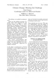
A hex mesh requires that all surfaces have associated quad meshes. This quad mesh may be generated before or during the hex meshing, but the need to match existing geometry generates significant geometric sensitivities. In particular, sliver faces with sharp angles cause severe distortion and propagation of this distortion through the mesh, since the sharp angle will force a double row of quad elements as shown in Figure 1. Also, any relatively planar triangular face requires subdivisions to accommodate the even boundary interval requirements as shown in Figure 2. These surface mesh requirements essentially force the smallest features to produce even smaller elements around them, accentuating the need for localized transitions and/or automated feature elimination.
4.1
Primitives
A hex-meshing primitive [7] is defined as a shape that can be recognized and meshed with a predetermined template mesh. Although a simple block shape itself can be considered a primitive, the template mesh usually involves inserting blocks into the geometry in a predetermined pattern and then subdividing these blocks into elements using a mapping algorithm. The templates usually allow for some deviations in shape and total element count, but not in overall topology or gross geometric shape. An example would be the template for hex meshing a tetrahedron as shown in Figure 3. This mesh template would apply equally well to an octant of a sphere since topologically the two volumes are equivalent. Other templates include the sphere and the hemisphere.
Figure 1. Minimal quad mesh in a sliver face.
Figure 2. Minimal quad mesh in a triangular face. There are also several pathologically difficult geometries to mesh using hex elements, including a pyramid shape. Although all such geometries will admit a hex mesh, the element quality may suffer significantly, particularly if large element size variations are involved.
4
EXISTING APPROACHES
Since the automation of hex meshing has significant payoff, a number of approaches have been explored. As mentioned earlier, trade-offs are associated with each technique, but the impact of the work should not be minimized. Significant gains in productivity can be attained, especially if the relative attributes of the algorithms employed are well understood. Thus, this section is intended to provide the necessary background, as well as to indicate adjustments, which serve to minimize the weaknesses of the various approaches. The algorithms can be classified into the following types: •
Primitives
•
Overlay Grid
•
Automated Decomposition
•
Advancing Front
Figure 3. Hex Meshing of a tetrahedral primitive involves the insertion of four blocks, each of which are mapped to produce hex mesh.
A significant primitive is the general sweep [8][9] which allows the sweeping of a surface quad mesh through an arbitrary path. This surface mesh maintains a constant topology cross-section during the sweep, but may deform as needed to match the path geometry. This generalized sweep is heavily used in practice as it allows more freedom since the cross-sectional mesh can be unstructured, as show in Figure
retained, the ones on the outside are eliminated, and those cut by the boundary are then adjusted to fit the existing boundary. Figure 5 shows the interior and boundary elements generated within the volume shown, using this technique. The effect of grid alignment on the resulting mesh is obvious.
4. Figure 4. The generalized sweep primitive allows an arbitrary mesh to be swept along a constant topology path. Advantages: •
No geometric decomposition is needed for the class of problems handled by the respective primitives.
•
Meshing is fast.
•
Element quality is relatively high as long as the template matches the geometry well.
•
The mesh is boundary sensitive and orientation insensitive.
Disadvantages: •
The applicable class of geometries is relatively small. Only those volumes whose topologies match exactly and whose geometries are basically aligned qualify.
•
In most cases, the primitive determines the surface mesh. Thus the ability to interface to adjacent meshed volumes is low, and requires that the adjacent volume be able to incorporate the primitive mesh. The exception would be the general sweep where the swept surface mesh is arbitrary.
4.2
Overlay Grid
The overlay grid techniques [10][11][12][13] rely on the use of a grid that encompasses the volume to be meshed. Traditionally this grid is structured and aligned with the coordinate axes. This background grid is then intersected with the geometry to determine elements that are inside, those that are cut by the boundary and those that are outside the volume being meshed. The elements on the inside are
Figure 5. Interior and boundary mesh within a volume, using an overlay grid technique is shown. The middle mesh shows the use of an aligned grid, while the bottom mesh shows the effect of a nonaligned one. Advantages: •
This technique is highly automated and applicable to most geometry. For these reasons the technique has been very popular for inclusion in various commercial software packages.
•
•
If a regular structured grid is used, then an octree-based subdivision process can be employed to enhance the intersection process. This has some nice benefits in terms of storage and data structures. It also allows for easy refinement of the grid to capture needed features in the geometry. These techniques can be tolerant of bad geometry, as long as the element size is reasonably larger than the gap and overlap problems.
Disadvantages: •
The mesh is not boundary sensitive. The best elements tend to be interior to the volume where the background grid is unchanged. The worse ones are conversely near the boundary where modifications have to be made to accommodate for the existing geometry.
•
The surface mesh is completely determined by the algorithm. This limits the applicability of the algorithm to only volumes with no pre-existing surface mesh. If all volumes are meshed together, it is plausible to maintain a conformal mesh on the interface between connecting volumes. Otherwise, any connected volume is forced to use the existing interface mesh generated by this technique.
•
The algorithm is orientation sensitive. A brick aligned with the axes produces a good mesh. One not aligned will produce a lot of poor quality elements. By aligning the structured grid with some natural orientation of the body or by using a completely arbitrary background grid, some of these sensitivities can be avoided.
•
Conformal mesh transitions from fine to coarse are difficult. Non-conformal transitions are often necessary.
4.3
Automated Decomposition Techniques
4.3.1
Geometric Decompositions
Several systems have been developed whose aim is to section the geometry into pieces that are meshable [14][15][16][17]. In many ways these algorithms try to mimic the manual approaches engineers have been using to generate a full hex mesh. This requires that the algorithm reason about the geometry. In particular, aspects of the geometry have to be identified which should be sectioned in order to simplify the geometry and eventually allow the available primitives to be used. Although a set of features can be found and processed by the algorithms, such as reentrant corners, small exterior angles, etc., one real obstacle preventing use on a general class of geometries is the ability to determine how features interact, as shown in Figure 6. This requires some type of global view of the geometry. To provide this more global view of the geometry and its structure, there has been work to create a skeleton from the geometry that provides a simpler interpretation of the shape [14][17]. This skeleton is then traversed and interpreted to guide the generation of geometric cuts.
Automated decomposition techniques attempt to decompose the volume being meshed into pieces, which themselves can be meshed using existing algorithms. Usually these pieces are recognizable primitive shapes (i.e. a brick) or swept volumes. This approach is highly dependent on being able to identify and/or decompose the geometry appropriately. Ideally, one would hope for as rich a suite of primitives as possible, although some systems are based solely on a block/mapping primitive only. There are three distinct classes of decomposition techniques: •
geometric cuts performed on the geometry before meshing
•
mesh partitioning during the meshing process
• virtual primitive assembly Although the basic idea of sectioning a volume to allow meshing is similar, the approaches have far different attributes - thus each will be reviewed independently.
Figure 6. Interacting features are often difficult to identify when performing geometric decompositions.
Advantages: •
Mesh is boundary sensitive.
•
Decompositions are usually orientation insensitive.
•
Disadvantages: •
Feature interactions are often missed by local feature based systems.
•
Skeletal methods can introduce strange couplings between the skeleton and the actual decomposition.
•
The generation of the skeleton may prove difficult or impossible, and is usually dependent on having a valid geometry.
•
The geometric cuts necessary to avoid generation of sliver faces may be quite complex to specify and/or find. The ability to make such cuts is dependent on the CAD/geometry system available.
•
Feature elimination before decomposition is often needed.
4.3.2
Significant de-featuring may be needed to transform complex faces into allowable topological configurations for the tools. This then assumes that the user is reasonably trained in the requirements of the algorithm.
Mesh Partitioning
Some decomposition techniques [18][19][20][21] perform the decomposition integrally during the meshing process. These techniques tightly control the surface mesh to insure that decomposition is possible. An example cooper mesh, which uses mesh partitioning, is shown in Error! Reference source not found.. In mesh partitioning approaches, the decompositions occur integrally with the meshing process by using an interior mesh as the cutting mechanism (i.e. no geometric cuts). The meshing primitives then range from a mapped block to a general 2.5D sweep.
Figure 7. An example mesh using the cooper tool which uses the mesh partitioning approach.
Advantages: •
No dependence on geometric operators.
•
Surface mesh generation process accommodates interactions between features by imprinting the features on appropriate unmeshed faces.
•
Mesh is boundary sensitive and orientation insensitive.
Disadvantages: •
The alogorithm is applicable to a limited class of geometries.
•
Algorithms have to be able to understand or classify all aspects of the geometry with respect to their internal decomposition process (e.g. cap faces and side faces). Users can help the algorithms understand the geometry by designating identifying attributes (e.g. vertex-type and source faces) in a semi-automated way.
•
The surface mesh is highly controlled by the algorithm. Interfaces to adjacent volumes have to be pre-meshed in an acceptable manner (e.g. submapped).
4.3.3
Virtual Block Assembly
One way to essentially decompose an object is to replace representation of the geometry with a composition assembly of bricks [22]. In this work, virtual cubes assembled and attached to the actual geometry. Once lattice of cubes is appropriately assembled, meshing of cubes with hex elements is relatively trivial.
the or are the the
Advantages: •
The virtual cubes provide a topology that controls the mesh structure.
•
The underlying geometry can be attached to provide better geometric definition than provided by the unattached virtual cube.
•
Geometric features can be easily ignored since the cubes define the topology of the mesh.
•
This method is highly tolerant of bad geometry.
Disadvantages: •
The creation of the assembly and attaching the geometry can be tedious.
•
Problematic geometries may be difficult to assemble (e.g. the pyramid) and be expertise intensive.
•
Mesh size propagation is dependent on the assembly structure.
•
User interface issues are paramount to success, as automation is low.
4.4
discussion here on some ideas that are based on the fundamentals of the constraints and goals of automated conformal hex meshing. From the techniques presented, it is helpful to identify salient features that could possibly be used in some combination in alternative approaches. One can easily combine the “primitives” category into the “automated decomposition” category where they are currently used, leaving basically three approaches to hex meshing. In order to facilitate the discussion about possible future areas of work, I will attempt some global observations about the three approaches: •
Overlay Grid. The overlay grid is the most automated, but also produces the most concern with boundary sensitivity and size adjustments. It does not control the surface mesh or use an existing surface mesh, but imposes a surface mesh based on intersections.
•
Automated Decomposition. The decomposition approaches produce the better mesh but are the least automated. However, they control the surface mesh explicitly; either to allow decompositions or accommodate desired primitives.
Advancing Front Techniques
Advancing front techniques are designed to work from the boundary of the mesh inward [23][24]. From the surface mesh, layers of elements are inserted to form the volume mesh in the interior of the volume. As the surfaces begin to intersect, they are connected in attempts to form a valid hex mesh. In general this task has proven intractable, and the use of mixed element types interior to the volume becomes necessary to fill the void [25]. These techniques lack robustness. The connectivity constraints of a conformal hex mesh create significant difficulties when trying to match intersecting surface mesh fronts. A novel approach at trying to solve the connectivity constraints led to the development of whisker weaving [4][26]. This approach converts the surface mesh to its dual and then generates a connectivity of elements that would be valid within the given surface mesh. This connectivity is controlled geometrically by the surface mesh angles only.
•
Advancing Front. These techniques preserve the surface mesh but this seems to become their downfall. The connectivity issues are paramount to success, but arbitrary surface meshes often prevent success or limit resultant quality. I have labeled the included ideas based on combinations of the attributes of these techniques. None of these ideas have been explored adequately to determine ultimate feasibility, but the ideas will hopefully stimulate a few progressive thoughts for other researchers.
Advantages: •
Mesh is boundary sensitive and orientation insensitive.
5.1
•
Existing surface mesh can be used, maximizing ability to interface with adjacent volumes.
•
Input is largely independent of geometry. Thus no geometric operators are needed during meshing, similar to most tet meshing algorithms.
To overcome the boundary problems associated with the overlay grid approach, a more boundary sensitized overlay mesh could be used. Some work has been done to use a template mesh that is aligned roughly with the shape of the geometry and thus significantly reduce boundary distortions [11]. However, this work relies on the user to generate the boundary sensitive overlay grid. This requires that appropriate simplified geometry be generated and then meshed – detracting from the otherwise automatic approach.
Disadvantages: •
Technology is not mature enough for use.
•
Plastering requires mixed element types.
•
Whisker weaving element quality is a struggle.
•
Meshing is very time intensive.
5
IDEAS FOR FUTURE RESEARCH
As has been shown above, the approaches to solve the conformal hex meshing problem have been varied. Although any one of the techniques can claim limited success, there are still a lot of opportunities for advancement. Each of the techniques can and are being extended by various researchers and developers, in an effort to improve the results. Many of these extensions include the use of mixed meshes and or nonconformal interfaces. However, I would like to focus my
Boundary Sensitive Overlay Grid
To be effective the generation of the template mesh must be automated. The overall natural orientation of the geometry and an appropriately simplified shape must be deduced. This simple shape would have to be one that can be automatically meshed (e.g. limited to a cooperable volume) in order to maintain automation. Perhaps the work associated with shape determination [14][17] could be used to guide the automatic generation of a more boundary sensitized template mesh.
5.2
Virtual Primitive Assembly
The ideas associated with the virtual block assembly are intriguing. Rather than adjusting the existing topology until it is meshable, it attaches a meshable virtual topology to
approximate the geometric description. This also eliminates the need for clean, connected geometry. If the level of primitive is raised from a block to a cooperable volume [20](e.g. a topological cylinder in its simplest form), then the amount of manual effort could theoretically be reduced significantly. Just as a block carries with it an implied meshing topology, these primitives would carry a similar (albeit much more generalized) implied meshing topology. Such a primitive assembly would require attachment of the cap/source faces to geometric faces and some ability to automate the attachment of the side faces. Also, interactions between the primitives (side faces hooking to adjacent side faces) would have to be provided similar to a cube hooking to a neighbor cube. A more advanced implementation of such a system would allow coring of one virtual primitive by another, similar to the multi-axis cooper tool capability [18]. Using these virtual primitives instead of the actual geometry would insure that no other geometric or topological adjustments would be needed in order for meshing to succeed. This would eliminate the present need to clean up, de-feature, and then adjust the actual topology (via virtual operators) to conform to the requirements of the meshing tool. The savings here could be substantial, assuming that a high level of automation for the primitive assembly could be attained.
5.3
Surface Defining Advancing Front
Advancing front approaches assume an existing surface mesh. Yet, the existing surface mesh usually is the biggest obstacle to connectivity constraints. It seems that an advancing front approach that defines as much of the surface mesh as possible during meshing would be advantageous. It could be assumed that surface meshes interfacing with adjacent volumes would remain, but often this is only a small fraction of the total surface of the volume. In such cases, the ability to define the surface mesh as the front progresses would allow more control of the remaining surface mesh structure. The start or seed for the advancing front could be chosen to prefer the placement of layers of mesh. This would then retain some similarity to the sweeping algorithms, except that the layer topology could be adjusted as needed to provide for features encountered in the boundary as the front advances. The front would need to retain distortion measures to insure that the mesh size and quality was maintained as it advanced, and changes in layer and surface mesh topology (e.g. via wedges [24]) inserted as indicated by these measures.
5.4
Advanced Skeletal Decompositions
Based
Of all the existing techniques, one which seems to have significant unexplored promise is the skeletal based decomposition techniques. Original work [14] in this area was very intriguing, but the difficulty of generating the skeleton for volumes was prohibitive. Recent work [17] has
addressed this problem and included the use of a more general sweep primitive to reduce meshing constraints (i.e. interval assignment concerns). It seems that natural continuation of this research could be fruitful, with emphasis on reducing some of the more unnatural decompositions based on part thickness, etc. Also, combining this work with de-featuring attempts would prevent overly complex topologies (e.g. sliver faces, short edges, etc.) from muddying the skeletal shape characteristics of the object. As mentioned earlier, there may be merit in using this technique to guide the generation of a more boundary sensitive overlay grid. Likewise, skeletal techniques may also be useful in automating the initial placement of a virtual primitive assembly, thus allowing the user to adjust this placement if automation was not completely successful.
6
SUMMARY
This paper has provided an overview of the ideal attributes of hex meshing algorithms. It also reviews existing technology and provides a natural categorization of various approaches. The strengths and weaknesses are enumerated and conclusions as to their effectiveness drawn. From this review, brain storming about possible promising areas of research has been supplied. The results, although lacking in significant technical exploration, provide stimulation for those interested in this research area. The possibility for major future advances in automation and improvement of hex meshing algorithms is significant.
7
REFERENCES
[1] Benzley, S. E., E. Perry, K. Merkley, B. Clark, “A Comparison of All Hexagonal and All Tetrahedral Finite Element Meshes for Elastic and Elastic-Plastic Analysis”, p. 179-191, Proc. 4th Int. Meshing Roundtable, 1995. [2] Sheffer, A., T. Blacker, J. Clements, M. Bercovier, “Virtual Topology Operators for Meshing”, p 49-65, Proc. 6th Int. Meshing Roundtable, 1997. [3] Sheffer, A., T. Blacker, M. Bercovier,” Clustering: Automated Detail Suppression Using Virtual Topology”, Joint ASME/ASCE/SES Summer Meeting. June 1997. [4] Tautges, T., T. Blacker, S. Mitchell, “The Whisker Weaving Algorithm: A Connectivity-Based Method for Constructing All-Hexahedral Finite Element Meshes”, Int. J. Numerical Methods in Engineering, Vol. 39, 3327-3349, 1996. [5] Mitchell, S., “A Characterization of the Quadrilateral Meshes of a Surface Which Admit a Compatible Hexahedral Mesh of the Enclosed Volume”, Proc. 13th Annual Symposium on Theoretical Aspects of Computer Science, Springer, pp. 465-476, 1996. [6] Schneider, R., “Refining Quadrilateral and Hexahedral Meshes”, pp. 671-678, Proc. 5th Int. Conference on
Numerical Grid Generation in Computational Field Simulations, 1996. [7] Stephenson, M., T. Blacker, “Using Conjoint Meshing Primitives to Generate Quadrilateral and Hexahedral Elements in Irregular Regions”, ASME G0502B, 1989. [8] Knupp, P. M., “Next-Generation Sweep Tool: A Method for Generating All-Hex Meshes on Two-and-One-Half Dimensional Geometries”, p 505-514, Proc. 7th Int. Meshing Roundtable, 1998. [9] Staten, M. L., Canann, S. A., Owen, S. J. “BMSweep: Locating Nodes During Sweeping”, p 7-17, Proc. 7th Int. Meshing Roundtable, 1998. [10] Schneider, R. “Automatic Generation of Hexahedral Finite Element Meshes”, p 103-114, Proc. 4th Int. Meshing Roundtable, 1995. [11] Zhu, J., T. Blacker, “Overcoming Cartesian Grid Generation Obstacles”, Proc. 7th Int. Conference on Numerical Grid Generation in Computational Field Simulations, September 2000. [12] Taghavi, R. “Hexar: Automatic, Parallel and Fault Tolerant Mesh Generation from CAD on Cray Research Supercomputers”, Proc. 3rd Int. Meshing Roundtable, 1994. [13] Smith, R. “A Novel Cartesian Grid Method for Complex Aerodynamic CFD Applications”, pp. 709-718, Proc. 5th Int. Conference on Numerical Grid Generation in Computational Field Simulations, 1996. [14] Armstrong, C. G., D. J. Robinson, R. M. McKeag, T. S. Li, S. J. Bridgett, R. J. Donaghy and C. A. McGleenan, “Medials for Meshing and More,” Proc. 4th Int. Meshing Roundtable, 1995. [15] Blacker, T. D., M. B. Stephenson, J. L. Mitchiner, L. R. Phillips and Y. T. Lin, “Automated Quadrilateral Mesh Generation: A Knowledge System Approach”, ASME Paper No. 88-WA/CIE-4. [16] Liu, S. and R. Gadh, “Automatic Hexahedral Mesh Generation by Recursive Convex and Swept Volume Decomposition”, pp. 217-231, Proc. 6th Int. Meshing Roundtable, 1997. [17] Sheffer, A., M. Etzion, A. Rappoport, M. Bercovier, “Hexahedral Mesh Generation using the Embedded Voronoi Graph”, Proc. 7th Int. Meshing Roundtable, 1998. [18] Miyoshi, K., T. D. Blacker, “Hexahedral Mesh Generation Using Multi-Axis Cooper Algorithm”, Proc. 9th Int. Meshing Roundtable, 2000. [19] Hohmeyer, M. E., W. Christopher, “Fully-Automatic Object-Based Generation of Hexahedral Meshes”, p.129-138, Proc. 4th Int. Meshing Roundtable, 1995. [20] Blacker, T. D., “The Cooper Tool”, pp. 13-29, Proc. 5th Int. Meshing Roundtable, 1996. [21] White, D. R., L. Mingwu, S. E. Benzley, G. D. Sjaardema, “Automated Hexahedral Mesh Generation by Virtual Decomposition”, pp. 165-176, Proc. 4th Int. Meshing Roundtable, 1995. [22] Fluent, Inc., “GeoMesh User’s Guide”, 1996. [23] Stephenson, M. B. and S. A. Canann, T. D. Blacker, R. J. Meyers “Plastering Progress Report I, SAND892192, Sandia National Laboratories. 1992. [24] Blacker, T. D., R. J. Meyers, “Seams and Wedges in Plastering: A 3-D Hexahedral Mesh Generation
Algorithm”, Engineering with Computers, Vol. 9:8393, 1993. [25] Meyers, R. J., T. J. Tautges and P. M. Tuchinsky, “The “Hex-Tet” Hex-Dominant Meshing Algorithm as Implemented in CUBIT”, pp. 151-158, Proc. 7th Int. Meshing Roundtable, 1998. [26] Folwell, N. T. and S. A. Mitchell “Reliable Whisker Weaving via Curve Contraction”, pp. 365-378, Proc. 7th Int. Meshing Roundtable, 1998.