Nov 21, 2013 - Christian Richardt, Yael Pritch, Henning Zimmer, Alexander ... Yael Pritch 1 ...... [1] A. Agarwala, M. Agrawala, M. Cohen, D. Salesin, and.
Megastereo: Constructing High-Resolution Stereo Panoramas Christian Richardt, Yael Pritch, Henning Zimmer, Alexander Sorkine-Hornung
To cite this version: Christian Richardt, Yael Pritch, Henning Zimmer, Alexander Sorkine-Hornung. Megastereo: Constructing High-Resolution Stereo Panoramas. CVPR - International Conference on Computer Vision and Pattern Recognition - 2013, Jun 2013, Portland, Oregon, United States. pp.1256-1263, 2013, .
HAL Id: hal-00907858 https://hal.inria.fr/hal-00907858 Submitted on 21 Nov 2013
HAL is a multi-disciplinary open access archive for the deposit and dissemination of scientific research documents, whether they are published or not. The documents may come from teaching and research institutions in France or abroad, or from public or private research centers.
L’archive ouverte pluridisciplinaire HAL, est destin´ee au d´epˆot et `a la diffusion de documents scientifiques de niveau recherche, publi´es ou non, ´emanant des ´etablissements d’enseignement et de recherche fran¸cais ou ´etrangers, des laboratoires publics ou priv´es.
Megastereo: Constructing High-Resolution Stereo Panoramas Christian Richardt 1, 2 1
Yael Pritch 1
Disney Research Zurich
2
Henning Zimmer 1, 3
Alexander Sorkine-Hornung 1
REVES/INRIA Sophia Antipolis
3
ETH Zurich
Abstract We present a solution for generating high-quality stereo panoramas at megapixel resolutions. While previous approaches introduced the basic principles, we show that those techniques do not generalise well to today’s high image resolutions and lead to disturbing visual artefacts. As our first contribution, we describe the necessary correction steps and a compact representation for the input images in order to achieve a highly accurate approximation to the required ray space. Our second contribution is a flow-based upsampling of the available input rays which effectively resolves known aliasing issues like stitching artefacts. The required rays are generated on the fly to perfectly match the desired output resolution, even for small numbers of input images. In addition, the upsampling is real-time and enables direct interactive control over the desired stereoscopic depth effect. In combination, our contributions allow the generation of stereoscopic panoramas at high output resolutions that are virtually free of artefacts such as seams, stereo discontinuities, vertical parallax and other mono-/stereoscopic shape distortions. Our process is robust, and other types of multiperspective panoramas, such as linear panoramas, can also benefit from our contributions. We show various comparisons and high-resolution results.
Our Our result result Our result
Previous methods methods Previous
Our result Our Our result result
Figure 1. Comparison of our high-quality omnistereo panoramas to previous methods. Top: stereoscopic panorama created using our system (red-cyan anaglyph). Middle: close-ups of stitching seams (left; illustrated in 2D) and vertical parallax (right) visible with previous methods. Bottom: same close-ups with our improvements.
To overcome this limitation, Peleg et al. [15] proposed a method to generate omnistereo panoramas. Motion parallax is explicitly captured by taking images with varying centres of projection, e.g. by mounting the camera on a rotating arm (see Figure 2). A stereoscopic panorama can then be created by stitching specific strips from the input views. While successfully introducing parallax, this strategy suffers from a number of unresolved practical issues that cause disturbing artefacts such as visible seams or vertical parallax in the panorama (see Figure 1). While those issues may be unpleasant in 2D, they can lead to considerable misperceptions and even become intolerable when viewed stereoscopically [8].
1. Introduction Recently, there is a strong consumer interest in a more immersive experience of content, such as 3D photographs, television and cinema. A great way of capturing environmental content are panoramas (see Figure 1). Nowadays, automatic tools for stitching panoramas from multiple images are easily available, even in consumer cameras. For circular 360° panoramas, one usually assumes a common camera centre for all images to minimise stitching artefacts due to the motion parallax between the images [2, 23]. This can be achieved by simply rotating the camera around its optical centre. However, such panoramas inherently lack parallax and therefore cannot be experienced stereoscopically.
The principal reason for these artefacts is that in practice our camera can capture light rays only at quite a limited spatio-angular resolution, i.e. a finite set of images with finite resolution. This insufficiently-dense sampling of the scene manifests itself as visible discontinuities in the output panorama in areas where neighbouring output pixels have been synthesised from different input views with strong 1
parallax between them. Simply capturing more and higher resolution images is not a practically feasible solution, since this would result in orders of magnitude more data while not fully resolving those issues. Secondly, while the optical centres of all camera positions should ideally lie on a perfect circle [15], in practical acquisition scenarios and especially for hand-held capture, this is nearly impossible to achieve. In combination with perspective projection, this results in the mentioned additional issues such as vertical parallax. The goal of this paper is to make automated high-quality, virtually artefact-free stereoscopic panorama generation Figure 2. Our two capture setups: manumore feasible in ally and using a motorised rotary stage. practice. To this end, our technical contribution is twofold. First, we describe a solution for compensating for the unavoidable deviations from the ideal capture setup. Specifically, we describe robust solutions to correct the input views which resolve issues caused by perspective distortion and vertical parallax, obtaining an optimal alignment of the input images with minimal drift. Our resulting representation is compatible with previous panorama stitching and mosaicing approaches. Secondly, we analyse typical aliasing artefacts known from previous approaches that lead to visible seams caused by the truncations and duplications of objects. As a solution, we describe how to upsample the set of captured and corrected light rays using optical-flow-based interpolation techniques, effectively achieving a continuous representation of the ray space required for omnistereo panorama generation. By sampling from this representation, we are able to produce megapixel stereoscopic panoramas without artefacts such as seams or vertical parallax, and with real-time control over the resulting stereo effect. As demonstrated in the results, our contributions resolve central issues of existing techniques for both stereo- and monoscopic panorama generation, as well as for any multiperspective imaging method based on stitching, like x-slit [30], pushbroom [5] or general linear cameras [26].
This is for example well suited for capturing buildings along a street [1, 10, 16, 18, 28]. However, these approaches cannot capture both a 360◦ view of the scene and stereoscopic depth. Consequently, this idea was extended to panoramas by moving the camera along a circular trajectory with either a tangential [20] or orthogonal camera viewing direction [15], the latter being known as omnistereo panoramas. The key appeal of both approaches is that they capture a range of viewpoints for the same panorama, thus allowing stereoscopic renderings with varying baseline. However, in practice, a number of challenges remain as discussed next. Alignment. Before stitching the images into any kind of panorama, one first needs to align them relative to each other, which amounts to estimation of the camera motion. This can be achieved with a purely image-based method that estimates a parameterised motion model (e.g. a 2D homography) from image correspondences, for example using image registration techniques [14]. This strategy has the obvious drawback that it is ignorant of the scene geometry (depth) and only computes the optimal 2D alignment. These methods hence lead to artefacts if the scene has a complex depth structure. To solve this problem, one can estimate the scene depth of the panorama [12], and use this information to compute the ego motion of the camera [16, 17, 28], i.e. the image motion scaled by the depth. With this information, one can then compute the optimal (possibly curved) shape of each strip to be pasted. The problem of these methods is that estimating the shape of strips as well as the depth is computationally expensive while not resolving all problems. To obtain a best possible alignment, one can go one step further and leverage structure-from-motion algorithms [22, 25] to estimate the full 3D camera poses [1]. While being even more costly than the ego-motion computation, this potentially gives better results as it allows for global optimisation of camera poses. We show how to adapt similar techniques to achieve highly accurate alignment for omnistereo panoramas. Stitching. A major problem when stitching multi-perspective images is that parallax leads to disturbing seams, i.e. discontinuities between the stitched strips. One way to alleviate this problem is to blend between the strips using strategies like simple linear (alpha), pyramid-based [3], or gradient-domain blending [11]. These strategies effectively attempt to hide the discontinuities and thus only work well for mild seams. In the presence of significant discontinuities caused by strong parallax, they tend to leave noticeable artefacts. More importantly, however, is that in the context of omnistereo panoramas, we need concise control over the resulting output parallax in order to achieve proper stereoscopic viewing. While the above blending approaches might be applicable for monoscopic stitching, in stereoscopic 3D the resulting inconsistencies can become unacceptable [8].
2. Related work Standard panoramas capture a wide field of view of a scene as seen from a single centre of projection. Most commonly, they are created by stitching multiple photos into one mosaic; see Szeliski [23] for a detailed survey. In contrast, multi-perspective approaches [13, 24, 27] combine images taken from different viewpoints to create mosaics that cannot be obtained from a single centre of projection. One example are pushbroom images [5] that can be stitched from images taken by a linearly moving camera. 2
To rectify seams in a more principled way, previous work [16, 19] proposed to use more images to get a denser angular sampling of the scene, resulting in thinner strips and smaller discontinuities. This can be achieved by leveraging depth or optical flow information to interpolate novel virtual views. The main problem of these methods is that they either require to store all the interpolated images, which easily becomes intractable for high spatial resolutions, or cannot achieve realtime rendering, thus reducing the practical usability of the approach. Furthermore, these methods are prone to give artefacts for thin vertical structures as they are often missed in depth or flow estimates. Optical flow was also used for improving hand-held capture of 2D panoramas [9, 21], to remove the (in this case) undesired motion parallax. We describe an optical-flow-based ray upsampling that works on the fly and is specifically tailored to our context of efficiently creating high-quality, high-resolution stereo panoramas.
icant overlap and a large vertical field of view. Due to the optical distortion introduced by those lenses, the first crucial step to approximate the desired ray geometry is to convert those images such that they correspond to a pinhole camera model. We experimentally found that rational lens distortion models [4] provide significantly better results than the standard polynomial approach [7] targeting simpler radial and tangential lens distortion.
4.2. Correction of camera orientations Any deviation from the previously mentioned ideal capture setup (circular trajectory and coplanar principal axes) leads to visible shape distortions in a stereoscopic output panorama (e.g. tilted buildings, vertical parallax). We therefore correct the orientation and viewing direction of each input view to best approximate an ideal setup. We start by estimating the camera poses using general structure-from-motion with global bundle adjustment [22, 25]. For purely circular motions, restricted models could be used in principle, such as enforcing the camera positions to lie on a circle. However, using a more general approach enables us to create omnistereo panoramas also from hand-held input as well as from more general camera trajectories like a straight line. We then remove the inherent scale ambiguity by scaling coordinates so that the camera’s trajectory conforms to the actual physical dimensions.
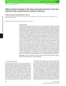
3. Method overview The fundamental principle behind omnistereo panorama generation, as introduced by Peleg et al. [15], is to create two sets of light rays: one for the left eye and one for the right eye, with all rays tangential to a circle (see Figure 4). In practice, one usually captures an image sequence with a camera moving along a circular trajectory with its principal axis parallel to the plane spanned by the camera trajectory (see Figure 2). An omnistereo panorama can then be created by stitching, for each eye, specific vertical strips from the aligned images, such that the above ray geometry is approximated. This approximation to the desired ray geometry typically suffers from inaccuracies of the capture setup and limited angular sampling, resulting in the previously mentioned artefacts such as vertical parallax (see Figure 1). In Section 4, we describe a specific transformation and alignment approach employing camera orientation correction, cylindrical image re-projection, and optimised homography matching that overcomes those issues. At the same time, our approach provides a representation that is compatible and hence applicable to improve the results of previous approaches. The second core challenge is the generally sparse angular sampling limited by the number of input images. This further deteriorates the approximation quality to the actually required set of rays and leads to aliasing artefacts (seams, truncation, duplication). In Section 5, we present a solution using flow-based stitching that resolves those problems.
The goal is now to rotate each camera coordinate frame towards the idealised setup with a common up-direction and viewing directions that are perpendicular to the camera trajectory. By rotating around the optical centre (using a homography) the transformation is scene independent and e hence does not introduce inaccuracies. Let P = KR[I|− C] be the decomposition of a camera’s projection matrix into e [7]. Further intrinsics K, rotation R and the camera centre C let R = [ x | y | z ] represent the left, up and viewing direction of that camera, respectively. We first compute a consistent up direction u across all images. For omnistereo panoramas, we obtain u by fitting a circle to all camera centres and using the normal vector n of the plane the circle lies in: u = n. For other trajectories (e.g. linear as for pushbroom panoramas), we compute u as the mean up direction of the individual camera coordinate systems. The mean up direction can also be used to disambiguate the normal direction in the omnistereo case, by choosing the direction that is closer to the mean up direction. Given the new up direction, the corrected coordinate frame can be easily computed as follows. The new viewing direction becomes v = u×x, and the new left direction is w = v×u (we assume that vectors are normalised before each step). The rotation that needs to be applied to a camera then is R′ = [ w | u | v ]T R−1 . This rotation is equivalent to the 2D homography H = KR′ K−1 applied to the image [7] and achieves the desired idealised capture setup.
4. View transformation and representation Here we describe the individual steps of our input correction. The resulting improvements are illustrated in Figure 3.
4.1. Optical undistortion to pinhole model For capturing stereoscopic panoramas, it is generally beneficial to use wide-angle lenses to capture images with signif3
middle view
right view
camera’s imaging plane to sample the corresponding output colour. Specifically, we approximate the extent of the image on the cylinder by tracing rays from the image border through the camera centre and intersecting them with the cylinder.
raw images
left view
lens-undistorted
– 3.9◦
0.0◦
3.3◦
orientation stabilisation
0.6◦
0.9◦
0.8◦
parallaxcompensated
4.4. Compact representation via 2D alignment
0.86◦
0.86◦
0.87◦
At this point, the re-oriented, parallax-compensated input views are in principle available for synthesising an omnistereo panorama. However, the current representation with the images projected onto the cylindrical surface is nonstandard compared to other panorama stitching approaches and requires extra bookkeeping about the locations of the images. We can exploit the fact that, thanks to our preprocessing, the remaining relative transforms between the images now are almost entirely simple horizontal translations without any rotational component. We therefore project the images back into a planar 2D setting that is compatible with previous methods for panorama generation (hence they can directly benefit from our corrections) and simplifies the following stitching process. We encode the alignment information about images via homographies as follows. For each pair of consecutive images, we leverage the reconstructed camera geometry to calculate the homography induced by a plane tangent to the cylinder halfway between the two camera centres in order to minimise distortions. For general camera trajectories, we instead position the plane at a fixed distance (see previous section) in front of the midpoint of the two camera centres, with the plane normal halfway between the viewing directions of the two cameras. We then decompose the plane-induced homography Hp (in normalised camera coordinates) to remove 5 of its 8 degrees of freedom to obtain a Euclidean transform. Specifically, if the chain of is�represented � � �as � � transformations � � K 0 I 0 A t sR t , (1) Hp = T = T v v 0 1 0T 1 v T v | {z } | {z } | {z }
Figure 3. Effect of our transformation and alignment. Lens undistortion restores rectilinear projection and straight lines. Correction of the camera orientations removes perspective distortion, and cylindrical projection compensates for vertical parallax.
4.3. Vertical parallax compensation The next issue is that in the standard pinhole model with a planar imaging surface, objects near the image border are larger than near the image centre. As a consequence, for non-linear camera trajectories, motion parallax between two input views consists of a horizontal as well as a vertical component. While the horizontal component is desirable for constructing a stereoscopic output image, the vertical component has to be eliminated in order to allow for proper stereoscopic viewing [8]. We resolve this issue by reprojecting each undistorted, orientation-corrected input image onto a cylindrical imaging surface, effectively removing the vertical parallax. We define the cylinder to be concentric to the circle fitted to the camera centres computed in the previous section, with the cylinder’s axis orthogonal to the circle plane and a specific radius. The cylinder radius determines the amount of horizontal scale changes for objects at different distances. In practice, setting the radius to the approximate distance of salient objects to the camera works well. Thanks to our SfM computation described in the previous section, the user has various opportunities to define those distances interactively or automatically from the scene geometry, optionally using additional tools like face detection, etc. To efficiently project each image onto this cylinder, we first establish a pixel grid on the cylinder at the desired output resolution and then project each pixel onto the pinhole
similarity
affinity
projectivity
we decompose sRK = A−tvT using QR decomposition in order to obtain the rotation R. The decomposition yields an orthonormal matrix Q∗ and an upper-triangular matrix R∗ . R is obtained by inverting the columns of Q∗ with negative diagonal entries to restrict the rotation to less than ±90°. Compared to purely image-based alignment techniques [14] that have typically been used in previous works on panorama generation [15], our correction and alignment steps described in this section are inherently consistent and drastically reduce the accumulation of positional errors (drift) in panoramas. In Table 1, we compare both the rotational and vertical drift. Our approach reduces drift in all cases by at least two orders to an unnoticeable 0.1°.
5. Flow-based panorama synthesis Given the aligned images, the basic approach of stitching an omnistereo panorama [15] is to extract specific strips from 4
a)
b)
c)
d)
α1α2
G
F
F
E l ca
cy lin dr i
rays for left-eye panorama
on cti oje pr
op tic al
IK
If M
c′ d′= c′′ d′′ without flow
C
IL
′′ ′ c′′ d c′ d
r
d fa
es ntr ce
P
G
p′ p˜
E β
D
C
p′ p′′ without flow
D
E
p′′
G
F
β
AB r
d
rays for right-eye panorama
a ne
IK
IL
with flow
f IL IK IM
Figure 4. (a) Illustration of rays required for creating a stereoscopic panorama and (b) deviation angle β. (c) Duplication and truncation artefacts caused by the aliasing. (d) Flow-based upsampling to synthesise required rays. Dataset
rotational drift IB Ours
vertical drift IB Ours
rooftop
98.7° 0.0043°
1.57° 0.0002°
street
82.7° 0.0154°
3.07° 0.0113°
mountain
66.8° 0.0600°
6.26° 0.0100°
Table 1. Rotational drift (roll) between both ends of a panorama, and remaining vertical drift after cancellation of rational drift, for image-based (IB) and our alignment with virtually no drift.
Nearest neighbour Nearest Nearest neighbour neighbour Nearest neighbour
Linear Linear Linear Linear
Pyramid-based Pyramid-based Pyramid-based Pyramid-based
Flow-based (ours) Flow-based Flow-based (ours) (ours) Flow-based (ours)
Figure 5. Comparison of different blending methods and their effect on typical seam artefacts encountered in stereo panorama stitching.
each image – dependent on the desired stereoscopic output disparities – and to combine them into a left and right output view. The omnistereo effect is achieved by collecting rays that are all tangent to a common viewing circle (Figure 4a). The correct sampling of input rays for the generation of a stereo panorama fundamentally depends on the targeted output resolution. Ideally, we would like to sample strips from the input views that project to less than a pixel’s width in the output, to avoid aliasing artefacts and deviation of rays from the desired ray projection. The deviation angles are defined as the angular difference between the ideal ray and the ray that is used for stitching (angles α1 , α2 in Figure 4b). Hence, the output quality depends mainly on the angular resolution of the capture setup, i.e. the number of input views rather than their spatial resolution. With a coarser angular resolution the deviation angles grow (approximately inversely proportional to the angular resolution) and stitching artefacts such as discontinuities, duplications, and truncations of objects become apparent, as visible in Figure 1. To mitigate these artefacts one generally employs some form of smooth blending [3, 11]. However, as demonstrated in Figure 5, such blending approaches may obscure these artefacts to some extent, but do not address the problem at its core. From a capture point of view, the conclusion would be to capture and process extremely high angular resolutions. However, a panorama in the order of 10 megapixels leads to an output width of about 7000 pixels for HD 720p input images. Thus, capturing roughly the same number of input
images to get a small enough angular resolution of less than 0.05° leads to prohibitive memory requirements. Note that this is orders of magnitude higher than what is required for our approach that can handle angular resolutions from 1° to 4°, but even 8° still produces agreeable results. In the following, we first analyse the expected aliasing artefacts and seams, and then describe a flow-based interpolation approach to upsample the available rays on the fly to match the required output resolution while resolving the visual artefacts efficiently and effectively.
5.1. Geometric setup In order to characterise the aliasing artefacts, consider the diagram in Figure 4c. Given two images Ik and Il , we need to collect the rays that are at an angle β to the principal axis. Let E and G be the intersections of these projected rays with the cylinder. Filling the strip EG in the panorama will in general require additional nearby rays to compensate for the relatively coarse angular resolution between input images. Now let us examine an object at distance dfar from the rotation centre that is further away than the cylindrical projection. The section CD will be duplicated in the stitched output since its projections c′ and d′ as well as c′′ and d′′ from images Ik and Il , respectively, to the cylinder are visible in both the green and the red strip (see also Figure 1, middle left closeup). On the other hand, objects in the section AB at distance dnear appear truncated in the final panorama (see Figure 1, left closeup). 5
Figure 7. Image-based alignment (left) is compromised by scene depth even after correcting for rotational and vertical drift, while our approach produces straight panoramas (right).
Panorama Panorama Panorama
k and l dependent on η then finally gives our flow-based blending result as ∗ SFlow k (x) = (1−η) · Ik (A0→k x + η · Fk→l (x)) ∗ + η · Il (A0→l x + (1−η) · Fl→k (x)). (3) As discussed in our results, an advantage of this blending is that it degrades gracefully in cases where the flow estimation shows inaccuracies. In terms of implementation, our technique requires querying the two images at warped subpixel locations of the form x + η · F∗ , which can easily and efficiently be implemented on a GPU using texture lookups. Thus, the flow-based blending comes without computational overhead during rendering. Of course, we need to precompute the flow fields, but our used optical flow method can also be efficiently implemented on a GPU [6], resulting in run times of a few seconds for HD input images.
Net flow Net Net flow flow
Figure 6. Panorama and computed net flow.
We resolve these aliasing artefacts by generating the missing rays using optical flow-based upsampling, as illustrated in Figure 4d. A point P at distance dfar is projected to p′ and p′′ from images Ik and Il , respectively, to the cylinder. The optical flow vector F at point p′ maps to point p′′ as p′ +F(p′ ) = p′′ . To avoid stitching artefacts, we interpolate the intermediate point p˜ between p′ and p′′ , effectively synthesising missing rays at the virtual camera location If M . The same concept applies to points closer than the cylindrical projection surface, as well as to other camera trajectories like the ones used for street-view panoramas.
5.2. Flow-based blending To implement the above idea, we require pairwise optical flow [29]. For a simplified notation, we describe the flowbased ray upsampling using the corrected images. However, the flow can be computed directly on the input images and undergo the same correction transformations. Let us denote the flow fields between any pair of adjacent images k and l by Fk→l . This provides image correspondences, i.e. Ik (x) ≈ Il (x+Fk→l (x)), where both images and the flow field are defined on the same pixel grid. However, this assumption is violated by our alignment strategy (Section 4.4) which aligns all images to the same global coordinate frame, with a different pixel grid for each image. Before we can use the flow fields to interpolate missing rays, we hence first need to compensate for the global alignment. This is done in two steps. First, the flow field Fk→l is defined on the pixel grid of Ik , and consequently it needs to be sampled in the coordinate frame of image k, at xk = A0→k x, where A0→k transforms from global coordinates to the local coordinate system of Ik . Secondly, the flow field also encompasses the Euclidean motion which is already accounted for by aligning the images in global space. This motion is given by A0→l x − A0→k x, which leads to the definition of the motion-compensated net flow as ∗ Fk→l (x) = Fk→l (A0→k x)−(A0→l x − A0→k x).
6. Results This section presents more results of our method and compares them to the state of the art. More results (with up to 140 megapixels) are shown in the supplementary material. We captured images using different types of cameras (DSLR, point-and-shoot, GoPro) both hand-held and using a motorised rotary stage (Figure 2). To maximise the vertical field of view, we used wide-angle lenses and oriented the cameras in portrait mode. Typically, we captured 100 to 300 images to get angular resolutions between 1° and 4°. In terms of run time, the main bottleneck is the SfM computation that can take up to several hours, but we hope that recent interest in fast SfM [25] will lead to a speed up. The remaining preprocessing steps currently take about 10 seconds per image in HD (720p) resolution per CPU core. After the preprocessing, we can stitch the panoramas in real-time at full screen resolution, which gives the user the freedom to adapt important stereo viewing parameters like interaxial distance or vergence on the fly; please see the supplementary video. Note that previous works [15, 16] did not achieve interactive rates without precomputing and storing synthesised views, which is impractical in terms of memory for high-resolution output, as detailed in Section 5.
(2)
Undistortion and alignment. We proposed specifically tailored methods for improving the input data. As shown in Figure 3, the lens undistortion produces straight lines despite using wide field-of-view lenses, the orientation correction removes perspective distortions caused by deviations from an optimal camera orientation, and the parallax compensation removes vertical parallax that impairs the stereoscopic
An example for the resulting net flow is shown in Figure 6. With this, the desired interpolation to synthesise inbetween light rays on the fly is achieved by warping corresponding pixels by a fraction of the flow, depending on the horizontal angular interpolation factor η between two images. Linearly blending between the two warped images 6
middle view
rightmost view
Our alignment
Image-based alignment
leftmost view
MAD mosaic mosaic (X-slits) (X-slits) MAD MAD mosaic (X-slits)
Our result Our Our result result Our result
MAD MAD depth MAD depth depth
Our net flow Our Our net net flow flow Our net flow
Figure 8. Image-based alignment results in severe shape distortions which our alignment overcomes. See also supplementary video.
impression (see also Figure 1). All these improvements lead to visually much more appealing panoramas. Furthermore, as shown in Figure 7, we obtain clean and linear results, and Table 1 quantitatively verifies that we successfully remove rotational and vertical drift. To further emphasise the importance of our correction steps, we captured a dataset with large parallax caused by a person close to the camera (see Figure 8). Here, it becomes clear that purely image-based strategies [15] lead to severe shape distortions, whereas our method produces a high-quality result without distortions.
Figure 9. Our flow-based blending compared to the depth-based stitching of Rav-Acha et al. [16] on their dataset ‘refaim’.
Linear blending
Nearest neighbour
1° per image 2° per image 4° per image 8° per image
Our flow-based blending
Stitching. As illustrated in Figures 1 and 5, previous techniques like linear or pyramid-based blending [3] basically only try to hide the seam artefacts and thus do not give satisfactory results in stereoscopic panoramas featuring significant parallax. Better results are expected if one tackles the under-sampling directly by using depth or optical flow to synthesise novel views [16, 19]. However, these methods either need to store prohibitively many synthesised images or sacrifice interactive rendering. Furthermore, they simply paste synthesised pixels, which leads to visible artefacts in places where the depth computation failed, e.g. at thin structures like the lamp post marked in Figure 9. Naturally, also optical flow estimation may fail for such thin structures. In this case, however, our solution automatically reduces to linear blending, which at these small locations allows to remedy the stitching problems and degrades gracefully. Further note that these results are actually not stereo panoramas, but linear pushbroom images as the input was captured from a car driving along the street. This shows that our contributions also apply for this input. See Figure 11 for examples of circular and linear panoramas. To further illustrate the strength of our flow-based blending, we apply it to severely under-sampled input. As shown in Figure 10, other blending methods fail entirely in these scenarios, whereas ours still provides reasonable results.
Figure 10. Results with decreasing angular resolution for different blending methods.
techniques to correct the camera orientations, remove undesired vertical parallax and to obtain a compact representation. Secondly, we use optical flow to upsample the angular input resolution to generate the optimal number of rays for a given output resolution on the fly, effectively resolving aliasing. In combination, our contributions allow for the first time to practically and robustly create high-resolution stereo panoramas that are virtually free from artefacts like seams or vertical parallax. Additionally, our efficient implementation enables to adjust stereo parameters (vergence, interaxial) interactively during rendering. We demonstrated that our contributions generalise to other multi-perspective stitching techniques like pushbroom images. We believe that our work is just one example that images captured at higher resolution and quality often pose novel challenges that require non-trivial extensions of previously developed principles and techniques. For future extensions of our work, we are interested in more general multi-perspective techniques like general linear cameras [26] and time-varying panoramas.
7. Conclusion We demonstrated a solution for creating high-quality stereo panoramas at megapixel resolution. To this end, we made two main contributions: first, we developed specifically tailored methods for correcting the input data. We proposed
Acknowledgements. We are grateful to Federico Perazzi, Gaurav Chaurasia and Maurizio Nitti for their assistance. 7
Figure 11. Stereoscopic panoramas corrected and stitched using our proposed techniques, shown as red-cyan anaglyph images . Top and left: Hand-held omnistereo panoramas captured by us, with 7 and 3 megapixels, respectively. Please refer to the supplementary material for high-resolution results of up to 140 megapixels. Right: Pushbroom image produced from Rav-Acha et al.’s ‘refaim’ dataset.
References
[15] S. Peleg, M. Ben-Ezra, and Y. Pritch. Omnistereo: Panoramic stereo imaging. PAMI, 23(3), 2001. [16] A. Rav-Acha, G. Engel, and S. Peleg. Minimal aspect distortion (MAD) mosaicing of long scenes. IJCV, 78(2–3), 2008. [17] A. Rav-Acha, Y. Shor, and S. Peleg. Mosaicing with parallax using time warping. In CVPR Workshops, 2004. [18] A. Román and H. P. A. Lensch. Automatic multiperspective images. In Eurographics Symposium on Rendering, 2006. [19] B. Rousso, S. Peleg, and I. Finci. Video mosaicing using manifold projection. In BMVC, 1997. [20] H.-Y. Shum and L.-W. He. Rendering with concentric mosaics. In SIGGRAPH, 1999. [21] H.-Y. Shum and R. Szeliski. Systems and experiment paper: Construction of panoramic image mosaics with global and local alignment. IJCV, 36(2), 2000. [22] N. Snavely, S. M. Seitz, and R. Szeliski. Photo tourism: exploring photo collections in 3D. ACM Transactions on Graphics, 25(3), 2006. [23] R. Szeliski. Image alignment and stitching: a tutorial. Foundations and Trends in Computer Graphics and Vision, 2(1), 2006. [24] D. N. Wood, A. Finkelstein, J. F. Hughes, C. E. Thayer, and D. H. Salesin. Multiperspective panoramas for cel animation. In SIGGRAPH, 1997. [25] C. Wu, S. Agarwal, B. Curless, , and S. M. Seitz. Multicore bundle adjustment. In CVPR, 2011. [26] J. Yu and L. McMillan. General linear cameras. In ECCV, 2004. [27] J. Yu, L. McMillan, and P. Sturm. Multiperspective modeling, rendering and imaging. Computer Graphics Forum, 29(1), 2010. [28] E. Zheng, R. Raguram, P. Fite-Georgel, and J.-M. Frahm. Efficient generation of multi-perspective panoramas. In 3DIMPVT, 2011. [29] H. Zimmer, A. Bruhn, and J. Weickert. Optic flow in harmony. IJCV, 93(3), 2011. [30] A. Zomet, D. Feldman, S. Peleg, and D. Weinshall. Mosaicing new views: the crossed-slits projection. PAMI, 25(6), 2003.
[1] A. Agarwala, M. Agrawala, M. Cohen, D. Salesin, and R. Szeliski. Photographing long scenes with multi-viewpoint panoramas. ACM Transactions on Graphics, 25(3), 2006. [2] M. Brown and D. G. Lowe. Automatic panoramic image stitching using invariant features. IJCV, 74(1), 2007. [3] P. J. Burt and E. H. Adelson. A multiresolution spline with application to image mosaics. ACM Transactions on Graphics, 2(4), 1983. [4] D. Claus and A. W. Fitzgibbon. A rational function lens distortion model for general cameras. In CVPR, 2005. [5] R. Gupta and R. I. Hartley. Linear pushbroom cameras. PAMI, 19(9), 1997. [6] P. Gwosdek, H. Zimmer, S. Grewenig, A. Bruhn, and J. Weickert. A highly efficient GPU implementation for variational optic flow based on the Euler-Lagrange framework. In ECCV CVGPU Workshop, 2010. [7] R. Hartley and A. Zisserman. Multiple View Geometry in Computer Vision. Cambridge University Press, 2004. [8] R. T. Held and M. S. Banks. Misperceptions in stereoscopic displays: a vision science perspective. In APGV, 2008. [9] S. B. Kang, R. Szeliski, and M. Uyttendaele. Seamless stitching using multi-perspective plane sweep. Technical Report MSR-TR-2004-48, Microsoft Research, 2004. [10] J. Kopf, B. Chen, R. Szeliski, and M. Cohen. Street Slide: browsing street level imagery. ACM Transactions on Graphics, 29(4), 2010. [11] A. Levin, A. Zomet, S. Peleg, and Y. Weiss. Seamless image stitching in the gradient domain. In ECCV, 2004. [12] Y. Li, H.-Y. Shum, C.-K. Tang, and R. Szeliski. Stereo reconstruction from multiperspective panoramas. PAMI, 26(1), 2004. [13] H. Lieng, J. Tompkin, and J. Kautz. Interactive multi-perspective imagery from photos and videos. Computer Graphics Forum, 31(2), 2012. [14] B. D. Lucas and T. Kanade. An iterative image registration technique with an application to stereo vision. In IJCAI, 1981.
8