Fast interfaces for DRAMs The fundamental circuity between a device’s interior logic and its external pins must evolve to meet new speed and power needs
At 100 MHz, each output driver must dissipate over 100 mW to drive a 100-pF lumped load rail to rail with 3.3-V supplies. Each 100-MHz DRAM could have as many as 16 output drivers operating simultaneously, collectively dissipating over 1.6 W. Not surprisingly, the fine print on data sheets for such parts commonly notes that “power consumption is specified with no load.” Transition times for 100-MHz signals are necessarily around 2 ns while, for a track distance of 15 cm on a printed-circuit board, transmission time is typically 1ns. If proper termination is not used, reflections will harm signal integrity under such circumstances. For many years, emitter-coupled logic (ECL) has been the usual choice for highspeed interfaces. The limited swing of ECL signals and ECL‘s ability to drive terminated lines made it superior in high-speed systems to the ubiquitous TTL interface. TTL, however, is relatively easy to implement in either MOS field-effect or bipolar transistor technology, whereas ECL interface specifications revolve around the technology of bipolar transistors. And attempts to match ECL with FET devices have, to date, had little success. Bipolar CMOS (BiCMOS) technology can overcome this ECL drawback, of course. But whether BiCMOS will be applicable to all future high-speed devices is debatable; the present economics of addine - bipolar .
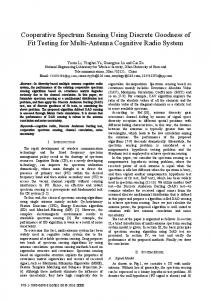
f dynamic RAMS and processors are to trade data at close to top speed, the interface between them must be re-engineered. At a minimum, it must support speeds in the 100-500MHz range, the low end for new dynamicRAM architectures and the high end for the speed projected for processors by the decade’s end. None of the types of interfaces now popular can do this while conserving power and cost to the desired degree. Yet it is hardly prudent to move on to a new form of interfaces without learning from and allowing for what has gone before. TODAY’S LIMITS. Current nominal 5-V interfaces include standard CMOS and TTL. CMOS is usually specified as having a minimum (worst-case) 2-V swing, but (unless dcloaded for some special application) usually goes rail to rail at 5 V. On the other hand, TTL is typically specified as having a 2-V swine because it does not eo rail to rail: the dc loid of its fanout and Yts emitter- ’ follower pull-ups prevent this from occurring. Even so, TTL typically achieves much more than a 2-V swing and, with a 5.5-V maximum Vcc (worst case), it may well operate at almost twice the 2-V level. Low-voltage CMOS and TTL are emerging; the nominal 3.3-V LVCMOS goes mil to rail to about a 3.6-V (worst-case) output swing, while LVTTL retains the 2-V output swing of its more power-hungry predecessor [see table, p. 561. Regardless of whether it is pumping lumped-capacitance loads or &ving k n i - capability to all MOS chips just for the outnated lines, a rail-to-rail swing consumes too put drivers casts doubt on its future. much power. The tracks on the typical NEW PATHS. Because of all these limitations, printed-circuit board look like 100-Q lines, new proposals are being put forward for but lumped-capacitance point loads in a bus achieving ECL‘s low swing and ability to environment can complicate things, lower- drive terminated lines with optimized MOS ing this figure to an effective characteristic circuits. Common to all the interfaces proimpedance (2,) well below 50 C4 [Fig. 11. posed here-center-tap terminated, Gunning transceiver logic, and low-voltage Richard C. Foss Mosaid Technologies Inc. differential signaling-is a restricted signal Beth Prince Texas Instruments Inc. swing, on the order of 1V or less; howev-
difficult to define an interface standard in ,a way that ensures
54
0018-9235/92/$3.0001992 IEEE
er, the base levels from which the swing takes place vary widely. In practical terms, it is difficult to define a standard interface in a way that ensures wide acceptance. It is not sufficient that adherence to a standard may result in a working system under ideal conditions; a standard must be based on a realistic means of testing for and specifying worst-case performance. Only then can a component that meets the specification be guaranteed to perform under realistic system conditions. Components with present-day interfaces are already running into test and specification problems. A chip with restricted-swing interfaces is very difficult to test to worstcase specifications. Nor is agreement easy as to what coIlstitutes a realistic environment. Various new approaches for specifying electric interface characteristics are being considered, such as supplying a set of simulation parameters for a circuit’s output drivers. This is a radical departure from the traditional component data sheet, and no one yet fully understands how to test an actual product to ensure that its parameters match those of the simulation.
Centef-tap temlnafed Internu? Richard C. Foss Mosaid Technologies Inc. Like low-voltage CMOS, which has adopted logic levels that reflect 30-year-old TTL standards, the center-tap t e m nated interface is an evolutionary, backcompatible standard that will ease the transition to new speed requirements. When used unterminated in shortrun situations, center-tap terminated (CTT) drivers give regular rail-to-rail swings and CTT receivers have standard input threshold levels. But for longer runs where termination is essential, CTT drivers automatically adjust to a restricted swing with a termination voltage near mid-level. The logic swing is set to a minimum of k400 mV relative to the termination voltage. The same level is used as an external reference input to CTT receivers, allowing tighter control of input levels thanwith simple CMOS input buffers. None of the circuit elements needed for CTT are really new. Input buffers using internal reference levels have been widely used in dynamic RAMS (DRAMS). Supplying the reference level externally allows the IEEE SPECTRUM OCTOBER 1%
ly rail-to-rail swings of 5-V TTL is far too are currently being used in a system progreat and drags out settling times far too totype. long. Even the adoption of low-voltage The logic’s IIO interface lets CMOS devices with output swings near 3 V will do devices communicate at very high speed little to help the arrival of the transmission over terminated transmission-line paths. speeds users demand for system perforwill also enable processors, application(11 At high speeds, traces on printed-circuit mance. What is needed is the speed and per- specific ICs (ASICs), and synchronous boards become transmission lines with formance of emitter-coupled logic or bipo- memories to opexate at 100MHz with concharactelistic impedance Zo,which is depen- lar CMOS (ECL and BiCMOS), but at the ventional clocking. With reduced clock skew a h t on the line’s inductunce and capacikznce power and cost of TTLcompatible CMOS. and better data synchronization, 400 MHz per unit length. Zf these lines are buses, inGunning transceiver logic (GTL) im- and higher data xates could be reached. stead of simple point-to-pointconnections, Zo plemented in CMOS easily meets these At 0.8 V (nominal), GTL‘s signal swing is is reduced to Z’bythe connected Iwds.(These needs. Additionally, since its output voltage comparable to that of ECL. Because of this loads, typically capacitive, are shown herefw level is independent of VCC,GTL can be a similaxity, most design tools and pxactices convenience as a single load capacitance, force for stabilizing the interface environ- developed in the last 20 years for building CT,but actually spreud along the transmis- ment as device voltages are reduced below top-performance ECL systems are applicasion line.) The size of the redudon in Zois the 5-V level. ble to GTL interface design. based on the ratio of line to load capacitunce. Unlike the current-driverinterfaces being The low signal-voltage levels keep on-chip When line termination RLmatches Z: there proposed, for which the output voltage can pow?‘ low. Whereas an ECL output typically are no refections and the signal is tmnsmit- change dramatically as the output load uses about 125 mW, a similar GTL circuit ted cleanly. But if RL is not equal to Z: changes, GTL output voltage levels are es- consumes only 10 mW, so it is practical to refections will distort the signal. sentially the same, both for terminated and include hundreds of GTL I/O circuits on one unterminated applications. As a singleended ASIC. minimum high-input level and maximum scheme, it does not require two wires for A simple way of seeing the power impact low-input level (the worst-case input levels) each connection and hence does not increase of Gunning transceiver logic is to compare to be tightened from 2.0 and 0.8 V, respec- the pin requirements for each device, as the power requirements for high-speed tively, to k200 mV, while maintaining ac- differential interfaces do. Nor is GTL sim- devices with 160 active I/O drivers that use ceptable margins for design differences and ply a specification in process or a prelimi- different types of logic levels: emittertesting requirements. Standard CMOS out- nary design; thousands of devices have al- coupled logic (ECL), backplane transceivput buffers in high-speed static RAMS ready been fabricated and boards using GTL er logic (BTL-a form of high-speed inter(SRAMs)are routinely tested with terminated lines, and the control of output swing by DATA OU t feedback techniques has many precedents. cOne circuit implementation uses a digital ristate ontrol form of feedback for preventing excessive swing when driving terminated loads [Fig. 21. The driver’s output state is monitored by an input receiver, which also serves as an input buffer when the terminus is an I/O port. While the output is opposite to the DATA OUT desired state, additional output drive is provided, so performance can match regul L 4 I lar LVCMOS when driving large, lumpedcapacitance loads. Once the output is in the desired state, the drive is cut back so that there will be a limited swing if a termination resistance is present. Latches ensure that I I any reflection forcing output levels back toI I r n ward the original state cannot re-trip the more powerful drivers. While back compatibility forces some Tr VREF compromises-in this case, slightly higher I Transmission I power dissipation in the drivers relative to Driver I line I Receiver an open-drain asymmetric driver-benefits I include lower system power from symmetriDATA IN cal drives. In the long term, systems employing CTT may evolve to use equal plus ; t 1v and minus supplies relative to a ground referDATA OUT \ ence plane, with signals symmetrically diB 6’ sposed.
m w
I
p u kI
.
Gunning transceiver loglc
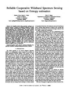
[2] Three techniques haw been -for h & - W interfaces: center-w tenniMteri (Crr), Gunning tmnsceiver logic (GTL), and low-voltage differentialsignaling (WDS). The CTT
Richard Rodgers Xerox Corp.
d r i w [top] can handle both stundurd and reduced signal levels; the termination mltnge, V,, controls the levels of the logic swing, which can be as h*h as 5 i? In a GTL intetface/bttom le^?], when the n-channel driver is turned ofi it is pulled up to the V , level (nominally 1.2 V) ly an external resistor; the receiver differentiallycompares an incoming signal to VREF, &pically0.8 i? The GTL signal range is 800 mi? W D S is unique in that it usespaired signal paths; diffkmtial signaling makes LVDS’s low-amplitude (400-mVsignals insensitive to noise, but doubles U0 pin count.
Systems will fully utilize the computing power of present-day very large-scale integration only if IC interfaces change xadically. The electric noise created by the nearFoss et al.-Fast interfaces for DRAMS
55
face developed by National Semiconductor Corp. in the late 1980s and now in the public domain), and GTL. If implemented with ECL, the drivers would consume 20 W with a 50-62,3.0-V termination at both ends. If the drivers were implemented using BTL, then they would require a power budget of 11W with a 50-62,Z.O-Vtermination. For the same number of drivers, however, GTL would draw only 1.5 W with 50-62, 1.2-V terminadevices that require high performance. GTL‘s low output-stage power allows devices to drive a local motherboard bus directly, without external drivers, thereby lowering cost and simplifying the interconnect. The device cost is low, since current CMOS technology is sufficient; BiCMOS could be used, but is not required. Further, GTL designs can be used without modification as the chip’s V D D level is reduced with new CMOS process developments; GTL parts designed for a V D D of 5 V can readily communicate with those designed for 3.3 V or less. The effect will be to stabilize the industry, as VoDmight be lowered more than once in the next decade. Second-generation GTL CMOS I/O transceivers are currently being used for both backplane and motherboard interchip bus signals in a high-performance computer system intended for volume production. This includes ASKSwith up to 160 GTL I/O cells operating at data rates greater than 100 MHz. Many companies are currently investigating or developing GTL devices, and Xerox Corp. has proposed GTL for industry standardization. At present, the technology may be licensed for a nominal fee. A GTL output driver typically uses an oDen-drain n-channel device, which, when t&ed off, is pulled up by an external terminating resistor to the terminating voltage, Vrr, which is equal to 1.2 V. A GTL input receiver is a differential comparator with one side connected to the reference voltage, VREF,which is typically 0.8 V. Alternatively, an active pull-up GTL output driver may be used for short signal paths with no external terminating resistor. For an upper-level return for the pull-up transistor, Vn is brought to a device pin so that the 1.2-V upper level is maintained. Figure 2 shows a bidirectional transmision line built using GTL U0 transceiver cells.
Characteristic Voltage levels for COmmOnly used logic
veloping a high-speed signal interface. The complement instead of a constant reference group is seeking an alternative to the ECL- so the receiver merely determines which of level signals specified by the IEEE Std 1596- the two is more positive. A shield on the 1992 Scalable Coherent Interface (SCO. The cable may further improve noise immunity P1596.3 work is nearing completion. Some [Fig. 2, bottom right]. At very high speeds, the advantages of this additional circuit prototyping and simulation is planned, and some questions remain on differential signaling become even more significant. The receiver is designed to ignore how to speclfy certain parameters. The group’s goal is to specify a new in- any voltage that appears equally on the two terface that will perform at least as well as conductors (common-mode rejection). In emitter-coupled logic (ECL) but cost less for high-speed systems of any real size, highCMOS implementations. It is becoming in- frequency noise makes the concept of a creasingly clear that fast signals must have system-wide ground or any other distributsmall amplitudes to keep power consump- ed reference a fiction. Noise problems of this tion to a level that can realistically and cost- sort have been endemic for years, and are effectively be handled by devices. Also, the often described as ground bounce. The usual variety of technologies likely to be used in solution is to slow the system with low-pass the next few years should be capable of filtering and “settlug” delays until it works. It is important to use a differential signalgenerating and receiving small-amplitude ing method that maintains a constant net cursignals. Most logic signals in use today are single- rent flow. The net signaling current usually ended. They propagate on a single conduc- flows back from the receiver termination to tor to a receiver, where their voltage level the transmitter through the ground, so any is compared to an easily distributed voltage high-frequency variations in that current standard (often the ground, but sometimes contribute to system noise. Even if the net current is constant, reversanother reference). But these signals co-exist with noise from ing the direction of the link (by turning many sources. If they are too small, com- drivers off at one end and on at the other) alters the sign of that current, causing noise. Thus for good system design the net current should be zero, or the links should neither be reversed nor turned on and off. (IEEE Std 1596-1992 Scalable Coherent Interface-known as SCI-mandates differential ECL signaling, with the termination current returned through the cable or cable shield. It also runs the links continuously and in one direction.) Reversing links, in fact, is incompatible with SCI’s scalability. Even if the net current is zero. the reversal inmunication becomes unreliable because of troduces a sensitivity to physical scale, benoise on the signal conductor or on the refer- cause the time required for reversal varies ence voltage standard. Practically, the limit with cable length. Low-wl&#edifhxential sl#11a1i11# for single-ended transmission is a little less The smaller the signal, the easier it is to drive and the more difficult it is to receive. than 1 V. David B. Gustavson For really high speeds and/or really low Thus a balance must be sought between Stanford Linear Accelerator Center power, however, much smaller voltage these conflicting requirements, and the apDavid V. James and Glen Stone swings are desirable. To eliminate the noise propriate one depends on the technology Apple Computer Inc. problems, the wiring is arranged so that the considered. The LVDS working group has reference voltage is exposed to the same chosen a signal peak-to-peak amplitude of Stephen Kempainen noise as the signal. Thus, the reference is 0.25 V (minimum) at the driver, centered on National Semiconductor Corp. generated near the signal driver, follows the +1.0 V relative to ground. Receivers should Low-voltage differential signaling, or LVDS, same path (twisted pair or coaxial cable), accept signals between 0 V and +2 .OV, thus is the current focus of the IEEE Computer and is compared to the signal at the receiv- allowing for up to 1 V of common-mode Society P1596.3 working group now de- er. It is even better to tmnsmit the signal noise or ground shift.
56
need Small amplitudes to keep power consumption to a
IEEE SPECTRUM OCTOBER 1992
This compromise seems compatible with a variety of technologies, and so the standard should be useful for some time. Differential signaling can double the I/O pin count (though this is partially offset by a reduction in the number of ground pins needed). Further, the higher speed capability lets engineen design with data paths that are narrower than would be possible with other, slower schemes, which also reduces the number of pins that would be needed. There are additional refinements. For example, the driver impedance is constrained to be reasonably constant, independent of the logic state; then common-mode noise that propagates backward and reflects off the drivers is not converted into differential noise by different reflection coefficients on the true and complement signal lines. The receivers have on-chip differential termination resistors, possibly active devices that are servo-matched to an external reference (which relaxes the IC fabrication tolerances). LVDS receivers can be designed to accept larger common-mode voltages (at some increase in cost). However, environments that need more than 1 V often need to handle many volts, requiring optical or magnetic isolation instead. P1596.3 is also defining the encodings for 4-bit- and 8-bit-parallelLVDS links suitable for SCI. The first applicationsfor the LVDS signals are a CMOS implementation of SCI, using 1-byte-wide links at 500 Mbytes per second, and RamLink [Pl596.4, described on pp. 52-53.] ABOUT THE AUTHORS. Richard C. Foss (SM) is president of Mosaid Technologies Inc., Kanata, Ont., Canada, and a member of Jedec committees on RAM memories UC42.3) and on low voltage and interface (IC-16). Betty Prince (M) is manager, new products, for MOS Memory Worldwide Marketing at Texas Instruments Inc., Houston. She has worked in semiconductormemories for most of her professional life, having held marketing positions with Motorola Inc. and Philips before joining TI in 1990. She is a member of Jedec committees JC-42.3 and JC-16; she founded the latter committee and served as its chair from 1989 to 1990. She is also a member of the IEEE Computer Society P1596.3 working group (Ramlink). Richard Rodgers is manager of memory and logic component engineering for Xerox Corp.’s Electronics Operations in El Segundo, Calif. He is also a member of Jedec committees JC-42.3 and JC-16. David B. Gustavson (M), David V. James (M), Glen Stone (M), and Stephen Kempainen (M) are members of the IEEE Computer Society F’1596.3 working group. Anyone who wishes to participate should contact working group chair Stephen Kempainen, National Semiconductor Corp., 2900 Semiconductor Dr., Santa Clara, Calif. 950528090; 408-721-4785; fax, 408-737-7218; email
[email protected].
+
ISS
et al.-Fast interfaces for DRAMS
T@im4a further ConrpstferArchitectu~:A Qu4dk&e ApprwCh by John Hennessy and David fitterson (MorganKaufmann, San Mateo, Calif.,
(second edition, Addis Mass., 1990). c’ Structmsby Stephen A. Ward and Robert H.HalsteadJr. (MIT Press, Cambridge, Mass., and McGraw-Hill New York, 1990) discusses structureson design
wide range of com-
Jedec has taken to issuing periodic updates on the status of standards activities in committees J C 4 3 and JC-16, despite a longstanding policy of not allowing discussions of ongoing standards activities. When they became available, Jedec standards may be obtained from Global Engineering Documents, 2805 McGaw Ave., Box 19539, Irvine, Calif. 92713-9539; 800-854-7l79. New DRAM technologies are discussed each year at the IEEE-sponsored International Solid State Circuits Conference (ISSCC). This year’s conference included a special evening discussion session on how ultralarge-scaleintegration 0 would affect dynamic RAM,in addition to a reguIar daytime session in which new DRAM technologies were discussed. Copies of the pmeedhgs may be obtainedfrom the IEEE Service Center Single Publication Sales Unit, 445 Hoes Lane, Box 1331,Fkcataway, N.J. 08855-1331.Next year, the conference will be held fmm Feb. 24 to 26 at the San
surveys the latest developments in personal computers and workstations in a special
puters was covered in the September issue
of S’mm.
ghosts” in last July’s Spectrum [pp. 50-521. S e m i c d W Memories by Betty Prince
view of memory chip technologies, including detailed discussions of the internal organimtion of static and dynamic RAMS, as well as such other solid-state memory technologies as video RAMS, field-altemble ROMs, and flash memories. For anyone interested in semiconductor memories, it is the basic text. Standardization efforts on synchronous dynamic RAMS were fvst reported by Ron Wilson in “Jedec hustlutg to spec new SDRAM” in the March issue of the Electraffic E&mmkg E m ,p, 1.The best direct source of information about the status of standardsfor synchronous DRAMS is the Joint Electron Device Engineering Council Uedec), 200 Pennsylvania Ave., N.W., Washington, D.C. 20006; 202-4574973.
Washington, D.C. 20005; 202-639-4255. L&&l Bus Harpdbook, edited by Joseph Di Giacomo (McGraw-Hill, New York, 1990),contains chapters that discusstopics such as transmission lines, crosstalk, and transceivestechnology, as well as other busrelated issues that are very applicable to memory systems. Some basic information on high-speed transceiverlogic can be found on pp. 191-196 of prince’spreviously cited book, Semiconductor Memorias. Also, the IEEE 3wml of sorid State Cimits often publishes articles related to this topic, and discussions can often be found in articles concerning dynamic RAM design. The use of lower working voltagesfor ICs, which has a heavy impacton interface technologies, was the focus of the article, “ICs going on a 3-V diet,” by Betty Prince and salters in the May 1992 issue m, pp. 22-25. Jedec Standards 8.0 which specify3-V IC requirements, obtained from Global Engineering uments at the address previously provided. ICrm9WLEDQMEWTSThe editors would like thankall of the contributing authors, but especially Betty Prince of Texas Instruments Inc.,Houston, Tms,for her help in comp tualizing and organizing this series, as well as in expediting the creation of the articles it contains. In addition, the editors would like to thank the panel of reviewers. Members of that panel included: Harvey C. Nathanson, Westinghouse Science & Technology Center, Pittsburgh; W. David Pricer, FBM Corp., Essex Junction, Vt.; Howard Sussman, NEC Electronics Inc., Natick, Mass.; and Lu Tian, Micron Semiconductor Corp., Boise, Idaho.
57


![Out of Humor [book review] - IEEE Spectrum - IEEE Xplore](https://m.moam.info/img/260x300/out-of-humor-book-review-ieee-spectrum-ieee-xplore_59adc4151723ddbcc5666d70.jpg)