OPEN ACCESS
www.mdpi.com/journal/sensors Conference Proceedings Paper – Sensors and Applications
MEMS IMU/ZUPT Based Cubature Kalman Filter applied to Pedestrian Navigation System Hamza Benzerrouk 1,2, Alexander Nebylov 1, Hassen Salhi 2,Pau Closas3 1
Saint Petersburg State University of Aerospace Instrumentation, SUAI, 19000, Saint Petersbug, Russia: email:
[email protected] 2 SET Laboratory ( Systèmes Electriques et Télecommande) of Electronic Department of Saad Dahlab University of Blida, 270, Soumaa, Algeria:
[email protected] 3 Centre Tecnològic de Telecomunicacions de Catalunya (CTTC), Av. Carl Friedrich Gauss, 7 08860 Castelldefels, Barcelona, Spain. Email:
[email protected] Published: 1 June 2014
Abstract: In most related work with Pedestrian navigation, indirect filtering approach is used based on linear error based Kalman Filter (KF). In this research, it is proposed to outperform this approach by the use of direct filtering approach. Based on only MEMS IMU, we propose the use of modern algorithms developed in the last decade; Sigma Point Kalman Filters (SPKF), and recently developed Cubature Kalman Filter (CKF) as a superior alternative to all previous filters. The CKF improves the mean and covariance propagation as compared with EKF and previous SPKF (UKF, CDKF). Although the CKF provides a better estimate of the orientation, velocity and position with Zero velocity UPdaTes (ZUPT) and Zero Angular Rate UpdaTes (ZARUT) measurements. Cubature Information Filter has been also implemented for sake of completeness. Keywords: accelerometers, gyroscopes, IMU, pedestrian navigation, Kalman filter, CKF
1. Introduction The problem of Pedestrian Navigation based on direct Kalman filtering recently deserved the attention of the navigation community, although more studies are necessary to master this application. Inertial sensors Microelectromechanical systems (MEMS) combined with aiding information is an accurate and efficient integrated system for navigation purposes under Gaussian conditions [2][3-4]. In our case, we consider that we use only IMU mounted on foot in order to determine the position, velocity and attitude of the body. A solution based on Zero Velocity UPdaTes ZUPT and Zero UPdaTes ZARUT has been developed in the last five years, which provides an aiding information to correct
2 inertial drifts and bias of gyroscopes and accelerometers and estimate person during walk. As a potential application, many attentions have been devoted to blind peoples navigation in urban environment and such development could be a potential solution for this complex problem. In this paper, the proposed solution implements an Information filter variant of CKF algorithm [1].
Fig.1. Strapdown Inertial Measurement Unit IMU / Mounted on foots (pictures from www.openshoe.org) 1.1 - INERTIAL SYSTEM MEASUREMENT
Due to drifts, bias, scale factors and noises of inertial sensors, ZUPT and ZARUT are used to aid navigation with bounded error of position, velocity and attitude estimation. In this work, we suppose both techniques of velocity update and angular rate update are applied with the use of three stationary conditions at ones. -ZUPT / ZARU Algorithms In its most basic implementation, a shoe-mounted inertial navigation system estimates and corrects drift errors via an assisted zero-velocity updating (ZUPT) indirect Kalman filter (IKF). In this work, the zero velocity update (ZUPT) is directly correcting and observing velocity calculated and delivered by INS through non linear filters. The algorithm relies on detecting the foot stance phase in order to build a zero-velocity-based pseudo-measurement which is delivered to the EKF, CKF and Cubature Information Filter CIF. 1.1. A. Zero Velocity Updating (ZUPT) The velocity measurement
z hVINS is given by: ZV V V Vˆ V V
(1)
where V is the measurement noise, modelled as a Gaussian random variable with zero-mean vector and covariance matrix RV . When zero velocity “V=0” is determined, this information is used to correct
the
non
linear
filter
which
uses
the
new
innovation
given
by:
Innov Z v h(V INS ) 0 V pred ( EKF / CKF / CIF ) Correcting velocity, it automatically leads to corrected coordinates after integration. 1.1.B. Zero Angular Updating (AUPT) By analogy to ZUPT algorithm, other scientists proposed to use the information of zero angular velocity update in order to get accurate estimation of attitude angles yielding also to more accurate
3 velocity and position integration and estimation by the Kalman filter variants. The intuitive idea behind ZARUT is that during stance phase, foot attitude is considered constant. It is possible to write attitude measurement as given below:
Z n
(2)
Where T is the vector containing the true IMU’s roll, pitch and yaw angles, with n white
Gaussian noise with Covariance matrix Q diag 2 2 2 .
In this paper, the attitude is
represented by Euler angles because of the bounded nature of motion, it is not needed to use to the quaternion model [2][5]. 1.2. INS/ZUPT/ZARU Integrated Navigation System Several architectures exist and were investigated in the literature [4-5,9]. Different filtering approaches with multiple state vector configurations have been widely simulated and experimented. We comment the most common. i.
The magnitude of the acceleration ak akb 1 akb 2 akb 3 2
2
2
tha m in 9 & tha m ax 11m / s ) 2
ii.
(3.a, 3.b)
1 th max 50 / s C2 otherwise 0
(4.a, 4.b)
The magnitude of the gyroscope,
k kb 12 kb 22 kb 32 (th m ax 50 / s)
iii.
1 tha min ak thmax C1 otherwise 0
The local acceleration variance must above a given threshold: a2 b k
1 k s b ak akb 2s 1 i k s
2
(5)
Where a kb is local mean acceleration value and s defines the averaging window (s=20 samples)., computed by the following expressions: a kb
k s 1 a b th a 1 k a q , C3 2s 1 q k s 0 otherwise
(6)
If these three “i,ii,iii” conditions are respected, it is then decided to select sensors outputs at time k as a ZUPT and ZARUT measurements. Proposal of Direct Filtering approach: In direct Kalman filter formulation, direct position, velocity and attitude angles are estimated. As it is known to be more computational demanding that indirect filtering, this approach has not been extensively explored in the past due to the CPU limitations previously explained. It is now possible to
4 propose such direct design as an alternative of high dimensional error state vector usually proposed in the indirect filtering approach. In this method, different non linear filters are applied, most of them have been described in [10][12][18], except for CKF which is described in the next section. IMU 3acc & 3gyro
Direct Position
non-linear Filter Stance
Velocity
(CKF/CIF)
Still phase detector
IMU
Electronic Compass
Attitude
250 Hz
Fig2.Direct filtering INS/ZUPT/ZARU ( Complex Information Computing based on Direct Filtering)
In this case, the state vector is computed in discrete time as given below, estimating directly the navigation states [3][5][10]: x k 1 f x k , l k wk
(7)
p n (k 1) v n (k 1)t p n (k ) w p n (k ) v (k ) v (k 1) C b (k 1) f (k ) f (k ) g n t w (k ) n b b n n vn n b b ψ n (k ) ψ n (k 1) E b (k 1) (k ) (k ) t w n (k )
(8)
With C bn , E bn are the transformation matrix defined as in [3][5][7-10]. lk :
sensors noise (gyroscopes /accelerometers output),
p n k :
position vector at time k v n k : velocity vector at time k, n k : attitude vector at time k
With the assumption that noises are non Gaussian in the process with: Q k1 : Covariance matrix of lk
( sensors noises), Qk2 : Covariance matrix of wk (system noise) Z k 1 H ( X k ) v k
(9)
H is defined as the dual observation ZUPT and ZARUT. In this case, we assume to have an additional direct observation of yaw angle from electronic compass, with:
Compass n .
(10)
This information is directly used to correct the yaw output of IMU. Real Output Data from IMU ADIS 16438: 6 5
W x output
4
W y output
W x output W y output
4
W z output
W z output 3
Angular rate in rd/s
Angular rate in rd/s
2 2 1 0 -1 -2
0
-2
-4
-3
-6 -4 23
24
25
26 27 Time in second (s)
28
29
20
20.5
21 21.5 Time in second (s)
22
22.5
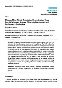
Fig3. MEMS IMU gyroscopes output ( original view and zoomed view of 03 angular rates x,y,z)
23
5
For direct filtering design, H is the identity matrix which means linear measurement. For tightly coupled design, H is the distance (or pseudo-distance) from beacons aiding navigation to the receiver (RFID or WiFi) mounted on foot with IMU, and in this case, measurements are strongly non linear [4]. 2. Experimental Section An application of the shoe-mounted inertial measurement unit IMU was tested [9]. The system hardware is composed by an: - IMU Analog Device 16367, equipped with accelerometers, gyroscopes and magnetometers that can be sampled at -250Hz frequency - Stance-Still step detector and an assisted AUPT-ZUPT “Direct Sigma Point Kalman filter” which we propose here. Experimental results are depicted in Fig.3 and Fig.4. These figures depict a superposition of the IMU’s outputs norm against the step detector output, as we can see the stance phases, characterized by almost no variation of the norm, are clearly identified. 6 W x output
Acc x output
5
W z output
Acc z output
4 3
1
Angular rate in rd/s
Accelration in "g"
W y output
1.5
Acc y output
2 1 0
0.5
-1
0
-2 -3 -0.5
26
27
28
29
30 31 32 Time in second (s)
33
34
35
25.2
36
The magnitude of the acceleration, must be between two thresholds
25.4
25.6
25.8 26 26.2 Time in second (s)
26.4
26.6
26.8
The magnitude of the gyroscope,
Fig4. MEMS IMU accelerometers output (view of accelerations and zoomed view of angular rates x,y,z)
This detection is based on multiple samples outputs. In our case we used 20 samples to determine if the system is in stationary phase or not such as described in [9]. 3. Results and Discussion Cubature Information Filter/ CKF based on ZUPT/ZARU Updates: Yaw angle vs Time s
Pitch angle vs Time s 0.3 INS True Pitch ZUPT/ZARU EKF CUBATURE KF CIF
-0.03
Pitch angle in degrees °
-0.04 -0.05 -0.06 -0.07 -0.08
INS True Yaw ZUPT/ZARU EKF CUBATURE KF CIF
0.25 0.2
Yaw angle in degrees °
-0.02
0.15 0.1 0.05 0
-0.09 -0.05 -0.1 -0.1 -0.11 56
57
58 59 Time in second (s)
60
61
12
14
16 18 Time in second (s)
Fig5. IMU Pitch angle and yaw angle estimation based on CKF/CIF
20
22
6 In Fig.5 it is possible to observe during walking pitch and yaw angles in the zoomed figures. The error of standalone inertial system is clear and visible comparing with the EKF, CKF/CIF estimation that are following the true trajectory. NORTH Velocity vs Time s
East Velocity vs Time s
East Velocity Meters/Second m/s
0.7 0.6 0.5 0.4 0.3 0.2
INS True Velocity ZUPT/ZARU EKF CUBATURE KF CIF
3.9 3.8
North Velocity in Meters/Second m/s
INS True Velocity ZUPT/ZARU EKF CUBATURE KF CIF
0.8
3.7 3.6 3.5 3.4 3.3 3.2 3.1
0.1 52
54
56 58 60 Time in second (s)
62
64
3 48
49
50 51 Time in second (s)
52
53
54
Fig.6. IMU “East Velocity” and “North Velocity” estimation based on CKF/CIF
In Fig.6 it is possible to observe that comparing with measurements, the most efficient and centred filter is CIF, somewhat analogue to CKF but after duration of time, after 56 second, it is possible to distinguish that CKF and EKF suffer slightly from bias and sensors errors at the opposite of CIF which provides the best estimate. 4. Conclusions After different simulations and analysis of results based on real data, the general conclusion is that MEMS ADIS IMU 16367 based on CKF is a good candidate for pedestrian navigation applications. CKF does not need the computation of any Jacobian or Hessian matrix. During different analysis, it has been observed that it is necessary to estimate accurately steps “stance” and “still” phases during walk in order to correct MEMS IMU from drifts and bias of gyroscopes and accelerometers. In parallel, in order to prevent initialization impact on the accuracy of coordinate estimation, CIF has been an excellent choice to estimate navigation states and presented more robustness against errors and bias of inertial sensors during long period of navigation [6][10]. Acknowledgments This work is based on open access project data provided by Openshoe http://www.openshoe.org/ Author Contributions The main contribution is the modification of the filtering approach without inertial error propagation. Conflicts of Interest Any potential conflicts of interest here.
7 References and Notes 1. I. Arasaratnam and S. Haykin,” Cubature Kalman Filtering”, IEEE Trans. Automatic Control, vol.54,no.6, pp.12541269,June 2009 2. Van der Merwe.R, E. Wan, and S. J. Julier. Sigma- Point Kalman Filters for Nonlinear Estimation and Sensor- Fusion: Applications to Integrated Navigation. In Proceedings of the AIAA Guidance, Navigation & Control Conference, Providence, 2004. 3. Benzerrouk,H, Nebylov,A. “Integrated Navigation System INS/GNSS Based on Joint Application of Linear and Nonlinear Filtering”, in proceeding of IEEE Aerospace conference, Big Sky, Montana USA, 2011. 4. C.Fernandez-Prades, P. Closas, J. Vilà-Valls, Nonlinear Filtering for Ultra-Tight GNSS/INS Integration, in Proceedings of the IEEE International Conference on Communications (ICC 2010), 23-27 May 2010, Cape Town (South Africa). 5. John L. Crassidis, « Sigma-Point Kalman Filtering for Integrated GPS and Inertial Navigation”, IEEE Transcation on, Aerospace and Electronic systems,2006.
6. A.R. Jiménez, F, F. Seco, F. Zampella, J.C. Prieto and J. Guevara, Improved Heuristic Drift Elimination (iHDE) for Pedestrian Navigation in Complex Buildings, IEEE 2011. 7. A.R. Jiménez, F. Seco, J.C. Prieto and J. Guevara Indoor Pedestrian Navigation using an INS/EKFframework for Yaw Drift Reduction and a Foot-mounted IMU. WPNC 2010: 7th Workshop on Positioning, Navigation and Communication 2010. 8. Francisco J. Zampella, Antonio R. Jiménez, F, Fernando Seco, J. Carlos Prieto, Jorge I. Guevara, Simulation of FootMounted IMU Signals for the Evaluation of PDR Algorithms. IEEE 2011. 9. John-Olof Nilsson, Isaac Skog, Peter H¨andel, and K.V.S. Hari ,Foot-mounted INS for Everybody – An Open-source Embedded Implementation. IEEE/ION PLANS 2012, pp. 140-145. 10. Francisco Zampella, Mohammed Khidery, Patrick Robertsony and Antonio R. Jiménez, F. Unscented Kalman filter and Magnetic Angular Rate Update (MARU) for an improved Pedestrian Dead-Reckoning. 2012 IEEE/ION Position, Location and Navigation Symposium, PLANS 2012.
© 2014 by the authors; licensee MDPI, Basel, Switzerland. This article is an open access article distributed under the terms and conditions of the Creative Commons Attribution license (http://creativecommons.org/licenses/by/3.0/).