International Journal of Machine Learning and Computing, Vol. 3, No. 5, October 2013
Mesh Decomposition Using Skeleton and Fuzzy Clustering Zhijing Wu and Shuangjiu Xiao
dependency on seed faces. Li et al. use the skeleton as sweep path and use the space sweep method to get the mesh segmented in [2], but the boundary is too smooth and loses the features of the mesh. Katz et al. proposed the fuzzy clustering method for decomposition in [4], combined with cuts, it gets a good performance in both components and boundaries. But the iterations to get the representative faces make it unsuitable for large models. In this paper we propose a new algorithm for mesh decomposition. Our work gets a fuzzy clustering using the geography distance to the skeleton, and then gets the boundaries from the fuzzy parts using the angular distance. In this way, we can get the meaningful components of the mesh without over-segmentation and the boundaries look fine. The rest of the paper is organized as follows. Section II gives the definition of components and outlines our algorithm. Section III describes the details of extracting skeleton. Section IV describes how to do the fuzzy clustering. Section V shows some results. Section VI concludes and discusses future works.
Abstract—As 3D models are used more and more in various applications, model decomposition acts as an important step for model understanding and can be used as a pre-processing step for different applications. This paper presents a mesh decomposition method based on skeleton. In recent years, a lot of work has been done to decompose polygon meshes to sub-meshes. No standard for the result, but the aim is to get reasonable sub-meshes and keep the boundaries between them fine. In this paper, we propose a mesh decomposition algorithm using skeleton and fuzzy clustering. Our method uses the skeleton of the mesh as the base to automatically get the meaningful components without over-segmentation and keeps a fine boundary using fuzzy clustering. Index Terms—Mesh decomposition, skeleton extraction, fuzzy clustering.
I. INTRODUCTION A problem may become easier when we cut the object to simpler sub-objects. In image processing, segmentation has been considered a fundamental problem, which is a necessary pre-processing step for many higher-level computer vision algorithms. In recent years, more and more efforts have been put in the mesh decomposition for graphics applications. Mesh decomposition can be used in many applications. Shlafman et al. [1] used decomposition in metamorphosis to give a correspondence between two models. Li et al. [2] used decomposition in collision detection to build a hierarchical data structures. Levy et al. [3] used decomposition to make parameterization and texture mapping be applied to each sub-component. Katz et al. [4] used decomposition to extract the control skeleton of mesh. Many other applications can benefit include simplification, compression, and modeling. Many approaches have been discussed for decomposing meshes in the past years. In [5] Mangan et al. proposed a watershed method for mesh decomposition. This approach generalized the watershed technique for 2D image processing to 3D polygon meshes. One problem of this approach is over-segmentation, which needs a post-processing step to resolve. Another problem is the result can easily be affected by noise of the mesh. Shalfman et al. proposed a K-means clustering algorithm for mesh decomposition in [1]. The mesh is well segmented, but the boundaries are always too jaggy and always not correct. A random walks method is proposed in [6]. In this case, meaningful components can be generated in a short time. The only problem is the
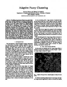
II. OVERVIEW By decomposition, we aim to get the mesh broken down into meaningful components. A component is meaningful if it’s distinguishable from the rest. For example, we can break down a human into head, body, hands, and legs, because we can tell each component from others. This doesn’t mean the result is unique, different ways to decompose a mesh will get different results. It’s difficult to tell which is better, just like you can take a hand as whole, and also you can break it down to palm and five fingers. Let S be an orientable mesh, a K-way decomposition of S is to break down S into K independent components, S1, S2 ... Sk, and each component Si is called a patch. To decompose a mesh well, two important characteristics are needed, geometry and topology. So we choose skeleton as the base of our decomposition algorithm. As shown in Fig. 1, we can get the geometry and topological information from the skeleton. We use a modified edge collapse method to extract the skeleton of the mesh.
Manuscript received September 10, 2013; revised October 25, 2013. The authors are with the School of Software, the Shanghai Jiao Tong University, Shanghai, 200240 China (e-mail: wuzhijingmichal@ sjtu.edu.cn,
[email protected]).
DOI: 10.7763/IJMLC.2013.V3.359
(a) geometric model (b) skeleton extracted Fig. 1. Skeleton of a duck model.
453
International Journal of Machine Learning and Computing, Vol. 3, No. 5, October 2013
Another key idea of our algorithm is fuzzy clustering. Assume we have extracted the skeleton of the mesh, and the number of skeletal edges is K. Each skeletal edge is taken as the representative of a patch, and we aim to get a K-way decomposition of the mesh. We first find the meaningful components and leave the boundaries between them fuzzy. Then we focus on the fuzzy areas to find the boundaries. The work flow of our algorithm is as below: 1) Extracting the skeleton of the mesh. 2) Assigning distances to all pairs of face and skeletal edge. 3) Get a fuzzy decomposition by assigning a probability value for each pair of face and skeletal edge. 4) Make use of angular distances to extract boundaries from the fuzzy areas.
cost edge and O(1) to refresh the data. So the total runtime of the procedure is O(n log n) . This method is suitable for us. The skeleton it gets is approximate the medial axis of the mesh and works well with noises to avoid over-segmentation. A 2D example of extracting skeleton is shown in Fig. 3 and the extracted skeleton of a cow model with 75524 faces is shown in Fig. 4.
(a) original mesh
(b) edge (v0,v5) collapse to v0
III. EXTRACTING SKELETON This section justifies how to extract the skeleton of a mesh using a modified edge collapse method. H. Hoppe proposed the progressive meshes in [7] and presented a procedure for mesh simplification. It will first assign a cost to all the edges in the mesh, and iteratively do the edge collapse transformation to the edge with the lowest cost. Our method is based on [7], but as we just need the skeleton for decomposition, a simple cost function is used instead. We use the Euclidean length of the edge as the cost. The procedure of edge collapse is shown in Fig. 2. Edge (u, v) is the edge with lowest cost in the mesh. It collapses to its endpoint u, and the position of point u changes to the midpoint of the edge. We assigned a list for each point to store the edges associated with it, we call this associated edges list. This will make it easier to refresh the related data after the edge collapse. When no triangle is incident to the edge, this edge is called a skeletal edge. The skeletal edges make up the skeleton. The procedure of the algorithm we use is as below: 1) Assigning costs to all the edges and assigning each point an associated edge list. 2) Find the edge with the lowest cost and collapse the edge. 3) Refresh the associated edges list of the remained point and refresh the cost of the edges in the list. 4) If an edge in the list is a skeletal edge, keep it in the skeletal edge list. Then remove it from the mesh and the associated edges list to keep its endpoints unchanged in later procedure. 5) Iteratively do step 2 to step 4 until no edge exists in the mesh.
(c) edge (v6,v7) collapse to v6
(d) edge (v1,v2) collapse to v1
(e) edge (v0,v4) collapse to v0 Fig. 3. 2D example of extracting skeleton.
Fig. 4. Skeleton of a cow model.
IV. FUZZY CLUSTERING The fuzzy clustering method based on the skeleton will be described in this section. Katz et al. proposed the fuzzy clustering method for decomposition in [4]. The algorithm uses a face to represent a patch and calculate the probability of other faces belongs to this patch based on the distance, and then uses the result to re-compute a more accurate representative face. This process is time consuming. After finally get the best representative face and make the fuzzy clustering, the exact boundaries are constructed from the fuzzy area. The basic idea of our fuzzy clustering algorithm is almost the same. But instead of using a face to represent a patch, we use the skeleton.
Fig. 2. Edge collapse.
With this method, we avoid using complex computing. For a mesh consists of n edges, it takes O(log n) to find the lowest 454
International Journal of Machine Learning and Computing, Vol. 3, No. 5, October 2013
A. Computing Distances The skeleton is approximate the medial axis of the mesh, so we can assume that the meshes around the skeleton form a cylinder, as shown in Fig. 5. Considering the ending patches like the head, fingers, and toes, finally we use the model shown in Fig. 6, a cylinder with a hemisphere on both ends.
promj =
weightij
(3)
weightim + weightij
The fuzzy clustering result of the cow model is shown in Fig. 8. The threshold ε we use is 0.02. For we have many short skeletal edges, the threshold shouldn’t be too large in case that no face is assigned to the patches represented by the short skeletal edges.
Fig. 5. Cylinder model for meshes around the skeleton.
Fig. 6. Cross-section of the model for meshes around the skeleton.
As shown in Fig. 7, assume edge (u, v) is a skeletal edge ki, and point c is the center of mass of an arbitrary face fj. The distance between fj and ki is Distji, which can be computed as show in (1). As shown in Fig. 6, we need an initial guess of r to complete the model. To make it simple, for edge (u, v), the
Fig. 8. Fuzzy clustering result of the cow model.
C. Extracting Boundaries We use the angular distance instead of the geography distance to extract the boundary from the fuzzy areas. We give the model of a patch in Fig. 6, combined with the distance computing shown in Fig. 7, we can see that in a novel situation, as shown in Fig. 9, if a face fj belongs to patch i represented by edge (u1, v1), the direction of its normal should be the same with v1c and have a huge difference from v2c . According to the situations in Fig. 7, define n j the Vec the unit vector of Vec , we normal of fj, and N (Vec )
radius is rj | uv | .
(a) α>π/2
(b) β>π/2
| Vec |
compute the angular distance as shown in (4). The patch m with the minimal angular distance to fj is the one fj belongs to.
(c) others Fig. 7. Distance between face and skeleton.
| uc | | Dist ji cv | uc uv | uc uv | | uv |
if uv uc 0 if uv cv 0
(1) Fig. 9. Angular distance between face and skeleton.
others
B. Fuzzy Clustering For an arbitrary face fi, we compute the weight between fi and each skeletal edge ki as shown in (2). Assume we have k skeletal edges, find the minimal weight among all the k weights for fi. Assume that weightim is the minimal weight, and then we believe that face fi most probably belongs to patch m. For skeleton m and any other skeleton j, the probability that fi belongs to patch m is computed as shown in (3). We define a threshold ε, if promj is less than 0.5+ε, then we think that fi may belong to patch j as well. In this case, we make fi belong to the fuzzy path. If for all other skeletal edges, promj is larger than 0.5+ε, then we make fi belong to m.
weightij Distij / rj
(2)
N (uc nj ) Angl _ Dist ji N (cv ) n j uc uv N (uc uv) n j | uv |
if uv uc 0 if uv cv 0 others
Fig. 10. Final decomposition of a cow model.
455
(4)
International Journal of Machine Learning and Computing, Vol. 3, No. 5, October 2013
The result of final decomposition of the cow model is shown in Fig. 10. We can see that the boundary between the body and head is smooth, but the boundary between the different patches of the leg is a little jaggy. Because the skeletal edge that represents the patch is too short and no exact boundary as shown in Fig. 9 exists between them.
Two models of the cow with different resolutions are given in Fig. 12, the high resolution one has 75524 faces and the low resolution one has 33244 faces. Thought the results are all fine, it’s obvious that the high resolution one get a better performance. Though our algorithm can avoid noise, but the trend of mesh distribution can affect the result. The skeleton of the low resolution extracted a skeleton that breaks the body to two parts and get a too long skeleton for the head, which finally make the decomposition result worse than the high resolution one.
V. RESULTS A. Some Results Some results of our decomposition is shown in Fig. 11. We get good performances in the man, hand, dolphin and many other models provided by X. Chen et al. [8]. They are decomposed to meaningful components without over-segmentation and remain good boundaries between each component.
C. Some Bad Results
(a) original model (b) skeleton (c) decomposition Fig. 13. Decomposition of the portrait sculpture.
(a) man
(b) hand (a) original mesh
(b) skeleton
(c) dolphin Fig. 11. Some results of decomposition.
B. Cow Model of Different Resolutions
(c) decomposition Fig. 14. Decomposition of the cup.
In this experiment, we try a portrait sculpture model with 54874 faces. Result is shown in Fig. 13. The skeleton we extracted consists of only one skeletal edge, and the whole model is taken as a whole. Then we decomposed a cup model with 30492 faces. The result is shown in Fig. 14. The main body of the cup is concave, and the skeleton we get for the main body is totally incorrect. Our method works badly with a concave model or a model which is too connective to break down.
(a) mesh of high resolution model (b) mesh of low resolution model
(c) skeleton of high resolution model (d) skeleton of low resolution model
VI. CONCLUSION In this paper, a 3D mesh decomposition method using skeleton and fuzzy clustering is proposed. A simple modified edge collapse method is used to extract skeleton, and then the skeleton is used as a representative to a patch to do fuzzy clustering. First we get the meaningful components and then extract edges from the fuzzy areas. Our algorithm can always get a good performance for convex meshes. As the skeleton extracting is the base of the method, any convex model can be
(e) result of high resolution model (f) result of low resolution model Fig. 12. Comparison between the cow model with different resolutions. 456
International Journal of Machine Learning and Computing, Vol. 3, No. 5, October 2013 [8]
decomposed into meaningful components with good boundaries and no over-segmentation. Our future work will mainly focus on skeleton extraction for concave models.
X. Chen, A. Golovinskiy, and T. Funkhouser, “A benchmark for 3D mesh segmentation,” ACM Trans. on Graphics (in Proc. SIGGRAPH), vol. 28, no. 3, 2009. Zhijing Wu was born in Jiangxi, China in 1989. He received his bachelor engineer degree from the Shanghai Jiao Tong University in 2011. Since 2011, he has been a postgraduate student in Shanghai Jiao Tong University. His research interests include computer graphics and image processing.
REFERENCES [1]
[2]
[3]
[4]
[5]
[6]
[7]
S. Shlafman, A. Tal, and S. Katz, “Metamorphosis of polyhedral surfaces using decomposition,” Eurographics 2002, 2002, pp. 219-228. X. Li, T. Woon, T. Tan, and Z. Huang, “Decomposing polygon meshes for interactive applications,” in Proc. the 2001 symposium on Interactive 3D graphics, 2001, pp. 35-42. B. Levy, S. Petitjean, N. Ray, and J. Maillot, “Least squares conformal maps for automatic texture atlas generation,” in Proc. SIGGRAPH 2002, ACM SIGGRAPH, 2002, pp. 362-371. S. Katz and A. Tal, “Hierarchical mesh decomposition using fuzzy clustering and cuts,” ACM Trans. Graph. (SIGGRAPH), 2003, pp. 954–961. A. P. Mangan and R. T. Whitaker, “Partitioning 3D surface meshes using watershed segmentation”, IEEE Trans. on Visualization and Computer Graphics, 1999, vol. 5, pp. 308-321. Y. K. Lai, S. M. Hu, R. R. Martin, and P. L. Rosin, “Fast mesh segmentation using random walks,” in Proc. Symposium on Solid and Physical Modeling, 2008, pp. 183–191. H. Hoppe, “Progressive Meshes,” in Proc. ACM SIGGRAPH, 1996, pp. 99-108.
Author’s formal photo
Shuangjiu Xiao was born in Sichuan Province in September 9, 1973. She received Ph.D. degree of Computer Aided Design in 2002 from Northwestern Author’s Polytechnical University, Xi’an, China. The major formal photo field of study of her includes computer graphics, human computer interaction. She is an associate professor of School of Software of Shanghai Jiao Tong University. She did postdoctor research during 2002 to 2004 in Computer Science and Technology Department of SJTU. Prof. Xiao is a member of the China Graphics Society and the China Computer Federation.
457