Mesh Networks for Digital Inclusion - Testing OLPC's XO Mesh Implementation Ricardo Campanha Carrano1, Michail Bletsas2, Luiz Claudio Schara Magalhães1 1
Departamento de Eng. de Telecomunicações – Universidade Federal Fluminense (UFF) Rua Passo da Pátria 156 – 24.220-121 – Niterói – RJ – Brazil 2
One Laptop Per Child One Cambridge Center, 10th floor, Cambridge, MA 02142, USA {carrano, schara}@midiacom.uff.br,
[email protected]
Abstract. This paper describes the planned tests and preliminary results obtained in the first field tests using OLPC’s XO laptop. The XO laptop mesh network is being evaluated to test its suitability to work in dense environments, where many laptops will be present and competing for the same gateway, and in sparse environments, where connectivity between pairs of laptops will be of foremount importance to maintain a path between the school and each laptop.
1. Introduction This work presents the preliminary finding of the RUCA project. RUCA stands for One Laptop per Child Network, or Rede do Projeto Um Computador por Aluno. It is a project funded by the Ministry of Science and Technology and the Ministry of Education, and administered by Rede Nacional de Ensino e Pesquisa (RNP). UFF’s Midiacom Lab is coordinating a team of five Universities in Brazil (USP, UNB, UFAM, UFPB, UFRGS) that will evaluate the capacity of OLPC’s XO laptop network to work in two different roles: the basic role to which it was designed, which is an educational tool (OLPC is an education project, not a laptop project), and the role as a tool for digital inclusion. Both are supported by a novel mesh network implementation, which will be described in Section 3. There is a whole taxonomy of mesh networks. All are characterized by the use of a wireless backbone, and the existence of multiple routes due to radio interconnectivity. They will be described in Section 2, Related Work. Depending on the type of mesh network, user nodes may or may not participate in forwarding packets, and can be connected using wires or not to the forwarding nodes1. XO’s mesh network follows the new IEEE802.11s standard, which is still in draft. There is no literature on tests of this type of mesh network. In the classroom, the mesh will be working at a very dense mode, and when the children take the laptop home, it will be working at a very sparse mode. This project wants to evaluate how XO’s mesh performs at both modes, and also the maximum range at which it will operate, with and without the aid of external antennas at the schools. Tests, tools and methodology will be presented in Section 4. The results
1
UFF’s Midiacom Lab’s Mesh Network has both wired and wireless user nodes, but they do not aid in forwarding, while OLPC’s XO mesh uses wireless user nodes that participate in forwarding
of the first field test are shown on Section 5, Preliminary Results. The paper ends with Conclusions in Section 6.
2. Related Work Mesh network is an umbrella name for a whole range of network architectures that use a wireless backbone and allow multiple routes because of the point-to-multipoint way radio works. The idea is an evolutive step away from wireless ad-hoc networks, which, although the object of intense research, never knew widespread use because of the basic lack of incentive for people to share their resources with other people [18]. Only in certain situations, like soldiers in a battle field, or workers at a disaster relief effort, adhoc networks could be used successfully because of the shared purpose of the group. Packet forwarding in ad-hoc, mobile networks was also very inefficient due to the problem of mobility, which caused many broken routes, with the subsequent lost and reordered packets that caused further problems up in the network stack. Mesh network has known enormous success because it can leverage on the low cost of modern consumer access points, and it can relax two constraints of mobile, adhoc networks. The first is mobility. Mesh repeaters are normally fixed2, and this aids the relaxing of the second constraint, which is limited power. In fact, most mesh nodes may be untethered in the network sense, but will be wired to a power source. Routes are therefore more stable, and nodes may forward packets without the fear of wasting much needed power. The commercial advantages of a mesh network for providing broadband are also clear, because the network can be built piecemeal, and can grow as the number of subscriber grows, which present a revenue model much different from traditional, cable and DSL broadband, which require a substantial investment to begin offering service. There are several mesh networks projects around the world. Examples of academic projects are ReMesh at UFF [20], RoofNet at MIT [1, 4], VMesh in Greece [19] and MeshNet at UCSB [7, 9]. Other examples are community networks, such as CUWiN in Urbana [8] and others at Dublin [11] and Taipei [14], and commercial projects, such as Microsoft Mesh [5,6], Google Mesh [12], Nortel [10], Cisco [3] and BelAir Networks [15] among others [2]. Mesh networks can also be classified as single radio, where the same radio is used for connectivity (backbone) and distribution (client access), and multi-radio, where different radios are used for each purpose. There is a review of mesh networks in [16] With the advent of commercial ventures, to get more bandwidth and reliability, mesh networks started to be engineered, with point-to-point multi-radio multi-frequency links, which in a certain sense strays from the original objective of a self-configured, multiple route network. The XO mesh is different from the mesh networks presented in this section in the sense that it is not a network level mesh. Generally, mesh networks use IP routing. XO mesh follows the emerging IEEE802.11s standard, which is still in draft form. The 2 XO’s mesh, on the other hand, is composed of mobile nodes, but it is expected that it will exhibit a mostly nomadic profile, where the laptop will be most of the time either at the school or home. This expectation may change with real use.
current proposal will be briefly presented in Section 3. The mesh network is a link layer level mesh, and uses the MAC addresses as identifiers for forwarding packets to the next hop towards the destination. Although this results also in requiring one route per destination (in the mesh) plus the route3 to the external world, it should work well for the number of hosts expected in a mesh network.
3. IEEE802.11s The definition for a mesh network, according to the draft of IEEE802.11s is: “A WLAN Mesh is an IEEE 802.11-based WDS which is part of a DS, consisting of a set of two or more Mesh Points interconnected via IEEE 802.11 links and communicating via the WLAN Mesh Services. A WLAN Mesh may support zero or more entry points (Mesh Portals), automatic topology learning and dynamic path selection (including multiple hop paths).”
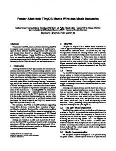
There are four types of entities that can participate in a mesh network, shown in Figure 1. Clients, which use the service, but do not participate in path selection and forwarding are called STA. Mesh points (MP) are entities that participate in the formation and operation of a mesh network. To provide service for clients (STA), an access point (AP) may be collocated with a Mesh Point. Those are called Mesh Access Points (MAP – MP AP in the figure). To connect the mesh to the wired infrastructure, a mesh portal was defined. It does both the work of a mesh point and works as a translator between the wired and wireless infra-structures.
Figure 1 – IEEE802.11s Entities and Communication Patterns
4. Planned tests The objective of the tests is to characterize the behavior of OLPC’s Mesh Network Implementation under different scenarios. A dense scenario is found in the schools, where students will congregate for class or for extra-curricular activities, and a sparse scenario is found when the students go home, and disperse in the surrounding 3
Or many possible routes, if the mesh has multiple connections to the Internet
community. There is also a mixed scenario, what we call “the lonely laptop”, where a single laptop tries to communicate with a dense mesh. Those tests will be conducted using iperf [13] and ping. The main challenge is that measurements in the 2.4GHz ISM band are hard. There are interferences from other radio sources such as microwave ovens, cordless phones and other wireless networks, which cannot be stopped because this is an unregulated band. There are environmental effects, due to topology and obstacles, which cause scattering and multi-path fading. The receiver sensitivity influences the measurement. In the same coin, different sources will also add variance to the measurements. There is also one challenge that is specific to this project, which is we are dealing with beta hardware and alpha software. This is inevitable due to the development method being used at OLPC, where hardware and software are being tested outside the development group, in the model of Open Source development. Groups around the world are receiving the equipment, and their use, like ours, is used to improve the next version. The last challenge of this project is to find the perfect place for range testing. The place has to be level, straight, with unobstructed line of sight, and at least one kilometer long. Ideally, its radio noise level should be low. Many locations were discussed, but there is a need to scout the place. Piratininga, which looked ideal on Google Earth, was found not to have a straight road long enough to be used. Itapuaçu, where the first field test was conducted, had too much radio noise. Scouting now is being done with a team with a laptop equipped with the wi-spy spectrum analyzer and a software called NetStumbler, used for wardriving. NetStumbler allows the discovery of wifi sources, while wi-spy shows any kind of interference in the 2.4GHz band.
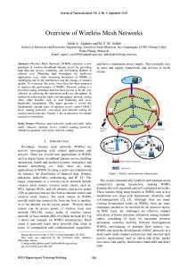
5. Phase One Preliminary Results As a preparation for the first outdoor tests, the crew went to a beach, called Itaipuaçu in the city of Maricá. The idea was to find a place with approximately one kilometer of plain, straight, unobstructed line-of-sight terrain in order to test the equipment and methodology to be used one week later. One kilometer was considered a long enough distance, based on previous preliminary tests [17]. To keep the fresnel zone as free of obstruction as possible, moving platforms of 1.20 meters were built. Early in the morning, a team was sent ahead to find a proper spot and to put marks at every 25 meters on the ground. Two XOs were used in the first setup. One was kept stationary at the base while the other was moved away in steps of 25 meters. The second setup used a Linksys access point equipped with an 18dbi omni directional antenna in lieu of the base XO. To test range, the mobile XO was moved away from the base in 25 meter steps. At each stop an icmp echo reply (ping) was run. The ping began to degrade (show mounting losses) when the two stations were 250 meters apart. At 275 meters, the losses began to be more frequent and at some point between 275 and 300 meters it stopped completely. After the “ping range” was established at 275 meters, the crew began testing packet loss moving back towards the stationary base and taking measures with iperf (in UDP mode) every 25 meters. No results could be registered in distances greater than 175 meters. The packet loss is summarized in Figure 2.
Packet loss versus distance 12,00% 10,00%
11,00%
8,00% 6,00%
6,20%
4,00%
7,00%
6,75% 4,40%
2,00%
1,19%
0,00% 25
2,95% 50
75
100
125
150
175
Distance in meters
Figure 2 – iperf UDP test results
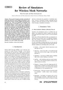
Figure 3 – wi-spy output During tests the bit rate was kept fixed at 2Mbits/s, so that automatic reconfiguration would not change throughput results. The XOs were set to use its virtual msh0 interface configured with iwconfig tool to operate in ad-hoc mode, channel 1, the least busy channel in that vicinity. In the Itaipuaçu neighborhood two wireless ISPs are in operation, using the ISM 2.4GHz band to provide internet access. Hence, many of the nearby houses are equipped with high gain directional antennas that make the spectrum highly busy in the test site. Figure 3 illustrates the use of frequencies when our equipment was completely shut down. This is a screenshot of the Channelyzer 2.0 tool, which is the companion software for the wi-spy ISM spectrum analyzer. Channelyzer output consists of three “views” that together show the use of the ISM band. On the top is the Spectral View, a waterfall graph that shows amplitude over time for each frequency. The brightness of each frequency/time coordinate represents
the amplitude of that frequency, with darker shading representing lower amplitudes. In the bottom is the Planar View, which shows amplitude over frequency display. And the middle graph is the Topographic View, which displays amplitude over frequency data similar to the Planar View, but instead of showing the current amplitude of each frequency it shows the popularity of each frequency/amplitude coordinate over the last 5 minutes. In Figure 3 we can clearly see two main sources of interference around channels 4 and 11, the second one being wider and stronger. Channel 1 was the least busy, although not completely free of interferences. The tests should also measure TCP performance, but iperf did not work. Later it was found that there was an issue with the virtual msh0 interface, used in the setup. At the time of this writing this issue has already been cleared by the developing team. 5.1. Preliminary test results The preliminary tests showed a series of practical issues concerning outdoor test equipment and imperfections in the tools and scripts that were used. First, the resolution of 25 meters proved to be too low. From 175 meters to 200 meters the packet loss jumped from 12% to 100%, showing the need of higher resolution near the borders of the range. For the next tests, the resolution is set to 10 meters. The laptop display legibility was also a concern. Although XOs are equipped with an effective reflexive screen which provide good legibility even under the sun, the auxiliary laptops need better shadowing to be effective. Car batteries proved to be good alternative power sources, as the XOs batteries typically would last only for about one hour. With the experience accumulated on this preliminary session, the test scripts and the next field test were planned. The next section describes the second field tests that took place on February 23rd 2007. 5.2. The following field tests After Itaipuaçu two other field tests were performed and its numbers are being analyzed as we write this article. On these tests we could reach even higher distances by choosing places with less interference on the 2.4GHz ISM band. In Jaconé, for instance, another beach in the Marica City, pings were still received at four hundred meters, and iperf data collect at three hundred meters. Despite the topographic similarities to Itaipuaçu, Jaconé offered a spectrum with less interference (interference on channels 6 and 11 were virtually non-existent), but on the other hand, after four hundred meters, the line-of-sight obstructions were considerably higher, preventing us from getting farther effective testing results. As one could expect from the electromagnetic theory, the height of the equipment platform is one of the most relevant issues during this type of tests. In another short test, in Barra da Tijuca beach (in Rio de Janeiro) pings between two XOs were successful at six hundred meters when XOs were placed higher. These results are consistent with calculations of Fresnel zone obstruction. As we can see on table 1, at 600 meters, the obstruction drops from 33% to 22% just by raising the laptops from 1,20 to 2 meters. As a rule of thumb, an obstruction of 40% is considered a practical limit to radio communication in microwave links. In the tests in Barra da Tijuca we had minor obstructions due to people walking on the site, and this could have contributed to arrive at 40% obstruction.
The Jaconé tests also revealed the limiting effect of interference in Itaipuaçu. We repeated the UDP tests summarized in Figure 2, obtaining not more than 1% loss at distances smaller than two hundred meters. At three hundred and fifty meters the same test registered a loss of only 8.1% - results much better than those obtained at with the busy spectrum of Itaipuaçu. Height of the equipment
Distance (meters)
0,70m
1,20m
2m
100
25%
10%
0%
200
32%
21%
5%
300
36%
26%
12%
400
37%
29%
16%
500
39%
31%
19%
600
40%
33%
22%
700
41%
34%
24%
800
41%
35%
25%
900
42%
36%
27%
1000
42%
36%
28%
Table 1 – Fresnel zone obstruction given height and distance These preliminary results also show that two XOs in ad-hoc mode can get better results, in terms of throughput and distance, than a XO associated with an access point, which was in this case a Linksys router with its two 2dbi regular antennas. This is yet to be confirmed in future tests.
6. Conclusions The XO mesh network evaluation is an on-going project. At the end, we want to be able to answer a series of questions, such as if the experience of a XO user is compatible to the experience of the user of a traditional computer, in the network sense, given the same conditions; if the XO works well in a classroom environment, and around the school; if it can be used as a means of digital inclusion, giving broadband access to the students and their families; what is the maximum range where we still get broadband access, and if this range can be extended through the intelligent use of antennas Our preliminary results show that the mesh network is functional, the previous problems with access points being solved. The maximum range has not been found yet because of the limitations of the current testing environment, but the XO has been shown to work up to 550 meters from each other, and 200 meters from an unmodified access point. With an omnidirectional antenna, the range is greater than 500 meters. We are still in search of the perfect test site. We are talking to the Brazilian Air Force, to use the Santa Cruz Air Base, and with the Army, to use Restinga de Marambaia. Both may present the necessary characteristics, and allow us to test the limits of the XO laptop and its mesh implementation. Meanwhile, we are starting tests with the dense scenario, and will be getting results soon.
References [1] J. Bicket, D. Aguayo, S. Biswas, and R. Morris, "Architecture and Evaluation of an Unplanned 802.11b Mesh Network", in ACM MobiCom, August 2005. [2] R. Bruno, M. Conti, and E. Gregori, "Mesh Networks: Commodity Multihop Ad Hoc Networks", in IEEE Communications Magazine, March 2005. [3] http://www.cisco.com/go/wirelessmesh, March 2006. [4] D. Couto, D. Aguayo, J. Bicket and R. Morris, “A High-Throughput Path Metric for Multi-Hop Wireless Routing”, in ACM MobiCom, San Diego, CA, September 2003. [5] R. Draves, J. Padhye, and B. Zill, "Routing in Multi-radio, Multi-hop Wireless Mesh Networks", in ACM MobiCom, Philadelphia, PA, September 2004. [6] R. Draves, J. Padhye, and B. Zill, "Comparison of Routing Metrics for Static MultiHop Wireless Networks", in ACM SIGCOMM, Portland, OR, August 2004. [7] C. Ho, K. Ramachandran, K. C. Almeroth and E. M. Belding-Royer, "A Scalable Framework for Wireless Network Monitoring", in WMASH, Philadelphia, PA, September 2004. [8] M. Lad, S. Bhatti, S. Hailes and P. Kirstein, "Enabling Coalition-Based Community Networking", The London Communications Symposium (LCS) , September 2005. [9] K. Ramachandran, E. M. Belding-Royer and K. C. Almeroth, "DAMON: A Distributed Architecture for Monitoring Multihop Mobile Networks", in IEEE SECON, Santa Clara, CA, October 2004. [10] S. Roch, “Nortel's Wireless Mesh Network solution: Pushing the boundaries of traditional WLAN technology”, in Nortel Technical Journal, Issue 2, October 2005. [11] S. Weber, V. Cahill, S. Clarke and M. Haahr, "Wireless Ad Hoc Network for Dublin: A Large-Scale Ad Hoc Network Test-Bed", ERCIM News, vol. 54, 2003. [12] http://wifi.google.com. September 2006. [13] http://dast.nlanr.net/Projects/Iperf/. January 2007. [14] www.nortel.com/corporate/news/newsreleases/2004d/11_17_04_taipei_city.html [15] BelAir Networks. http://www.belairnetworks.com. January 2007. [16] Akyildiz, I. F., Wang, X. and Wang, W. "Wireless mesh networks: a survey", In: Computer Networks Journal (Elsevier) v. 47, no. 4, p. 445-487, mar. 2005. [17] www.olpcnews.com/hardware/wireless/olpc_xo_btest-1_wifi.html. January 2007. [18] R. Kravets, C. Carter, and L. Magalhaes “A Cooperative Approach to User Mobility” ACM Computer Communications Review, vol. 31, 2001. [19] http://vmesh.inf.uth.gr/. January 2007. [20] D. Passos, D. Teixeira, D. Muchaluat-Saade, L. C. S. Magalhães, C. Albuquerque. Mesh Network Performance Measurements. 5 IITTS, 2006, Cuiabá, MT.


![Military Mesh Networks - MeshDynamics [PDF]](https://m.moam.info/img/260x300/military-mesh-networks-meshdynamics-pdf_648a8950098a9e34068b45b0.jpg)