We introduce mesh quilting, a geometric texture synthesis algo- rithm in which a 3D texture sample given in the form of a trian- gle mesh is seamlessly applied ...
Mesh Quilting For Geometric Texture Synthesis Kun Zhou∗ Xin Huang∗ Xi Wang∗ Yiying Tong† Mathieu Desbrun† Baining Guo∗ Heung-Yeung Shum∗ ∗ Microsoft
Research Asia
† Caltech
Abstract We introduce mesh quilting, a geometric texture synthesis algorithm in which a 3D texture sample given in the form of a triangle mesh is seamlessly applied inside a thin shell around an arbitrary surface through local stitching and deformation. We show that such geometric textures allow interactive and versatile editing and animation, producing compelling visual effects that are difficult to achieve with traditional texturing methods. Unlike pixel-based image quilting, mesh quilting is based on stitching together 3D geometry elements. Our quilting algorithm finds corresponding geometry elements in adjacent texture patches, aligns elements through local deformation, and merges elements to seamlessly connect texture patches. For mesh quilting on curved surfaces, a critical issue is to reduce distortion of geometry elements inside the 3D space of the thin shell. To address this problem we introduce a low-distortion parameterization of the shell space so that geometry elements can be synthesized even on very curved objects without the visual distortion present in previous approaches. We demonstrate how mesh quilting can be used to generate convincing decorations for a wide range of geometric textures. Keywords: texture synthesis, geometric detail, shell mapping
1
Introduction
Caught between the need for ever richer computer-generated scenes and the hardware limit of polygon throughput, early computer graphics researchers developed texture mapping as an efficient means to create visual complexity while maintaining the geometric complexity to a reasonable level. More general forms of textures, such as bump mapping and volumetric textures, were introduced to palliate the artifacts of image texturing, while still eliminating the tedium of modeling and rendering every 3D detail of a surface. However, the graphics processor on today’s commodity video cards has evolved into an extremely powerful and flexible processor, allowing not only real-time texture mapping, but also interactive display of tens of millions of triangles. Thus, exquisite details can now be purely geometrically modeled and directly rendered, without generating the well-documented visual artifacts of image-based textures such as lack of parallax, smoothed contours, and inaccurate shadows. This purely mesh-based representation of geometric detail turns out to be also very desirable as it does not suffer from most of the traditional limitations of modeling, editing, and animation, offering a versatile and unrestrictive tool for artistic creation. Alas, modeling such complex geometric details as veins, chain mails, ivies, or weaves is still a tedious process—more so than image texture synthesis, its 2D counterpart. Whereas many 2D texture ∗ e-mail: † e-mail:
{kunzhou,xinh,xwan,bainguo,hshum}@microsoft.com {yiying,mathieu}@caltech.edu
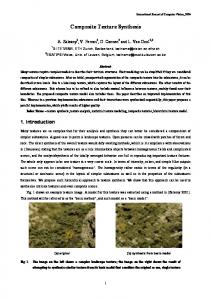
Figure 1: A bunny model decorated with two typical geometric textures using Mesh Quilting. Left: a non-periodic tubular weave mesh-swatch can be successfully grown over the surface; Right: even a chain mail structure can be seamlessly synthesized from the given swatch, preserving the integrity of each link.
synthesis techniques have been proposed over the past few years, the problem of creating mesh-based 3D geometric textures remains challenging. In this paper, we introduce a solution, called mesh quilting, to synthesize geometric details by stitching together small patches of an input geometric texture sample (see Figure 1). We also propose tools to further edit and animate these geometric details, facilitating the design of complex geometric textures on arbitrary meshes.
1.1
Related Work
Mapping textures on surfaces to add visual complexity has a long history in graphics; we will only review the most relevant references. Modeling of Geometric Detail on Surfaces The first successful representation for complex geometric details was introduced in [Kajiya and Kay 1989] as three-dimensional textures, and has since then been proven to be efficient for rendering complex scenes containing forests, foliage, grass, hair, or fur [Neyret 1998]. Procedural 3D texture synthesis [Peachey 1985; Perlin 1985; Perlin and Hoffert 1989] can extend the applicability of such techniques. However, manipulating and animating the content of these volumetric textures can be particularly delicate. Recently, [Elber 2005; Porumbescu et al. 2005] advocated a more versatile representation for geometric detail modeling using mesh-based details. Both method simply tiles textures over the plane and then maps the textures to 3D surfaces. However, this process is limited to periodic textures and most importantly it will produce texture discontinuity across chart boundaries since arbitrary surfaces do not have a global parameterization over the plane. Although a few other papers have proposed such a mesh-based creation of geometric textures on arbitrary meshes (see [Fleischer et al. 1995]), they are mostly restricted to the dissemination of simple texture elements over the surface, like scales or thorns, and do not allow the design of woven materials for instance. Example-based Texture Synthesis Texture synthesis on surfaces has, over the past five years, significantly increased the ease of designing complex image-based details on arbitrary meshes. A first category of algorithms [Turk 2001; Wei and Levoy 2001; Ying et al. 2001; Tong et al. 2002; Zelinka and Garland 2003] achieved such a synthesis based on per-pixel non-parametric sampling [Efros and
Leung 1999; Wei and Levoy 2000]. Based on the L2 -norm, a relatively poor measure of perceptual similarity, such algorithms are not applicable to a large spectrum of textures. The second category of algorithms synthesizes textures by directly copying small parts of an input texture sample (i.e., a swatch), an approach more amenable to all types of texture input. Earlier algorithms randomly paste patches and use alpha-blending to hide patch seams [Praun et al. 2000]. Recently, quilting [Efros and Freeman 2001; Liang et al. 2001; Soler et al. 2002; Magda and Kriegman 2003; Kwatra et al. 2003; Wu and Yu 2004; Zhou et al. 2005] generate significantly better results by carefully placing patches to minimize the discontinuity across patch seams. After placing those patches, [Liang et al. 2001; Magda and Kriegman 2003] simply use alpha-blending to hide patch seams, while [Efros and Freeman 2001; Kwatra et al. 2003; Zhou et al. 2005] further enhance the smoothness across the seams by searching for the “min-cut” seams. Since our human visual system is so sensitive to edges, corners and other high-level features in textures, [Wu and Yu 2004] proposes instead to extract a feature map from the sample texture, and perform feature matching and deformation to best keep the integrity of features. Other relevant texture synthesis techniques include an hybrid approach combining pixel-based and patch-based schemes [Nealen and Alexa 2003], texturing objects in photographs [Fang and Hart 2004], parallel controllable texture synthesis on GPU [Lefebvre and Hoppe 2005] and texture synthesis using Expectation Maximization optimization [Kwatra et al. 2005].
Figure 2: Modeling a knight’s chain mail shirt from a swatch.
1.3
Contributions
Shell Space Parameterization If a geometric texture given as a mesh over a planar surface needs to be mapped to a 3D curved surface, a one-to-one mapping between the geometric texture and the shell space (i.e., the thin layer around the curved surface) can be defined. Unlike previous methods which implicitly construct the shell space using normal displacement, [Peng et al. 2004] define a point-to-surface function to generate displacements for vertices. The shell map approach [Porumbescu et al. 2005] proposes to tetrahedralize both the shell space and texture space to build a bijective mapping between the two spaces using barycentric coordinates of the corresponding tetrahedra. However, and as admitted by the authors as a limitation, shell mapping is very sensitive to the height of the shell as it can introduce significant distortion resulting in noticeable artifacts.
We built upon the traditional texture synthesis framework to design a mesh-based geometric texture synthesis technique to decorate arbitrary meshes: from a base mesh and a given 3D texture swatch, a geometric texture, locally similar to the swatch everywhere, is synthesized over the base mesh. In contrast to previous volumetric texture methods, a unique feature of mesh quilting is that both the input geometry and output geometry are represented by triangle meshes. Moreover, our technique maintains the integrity of geometry elements in the synthesized texture so that subsequent texture editing and texture animation can be easily performed. For stitching together geometry elements our algorithm finds corresponding elements in adjacent texture patches, aligns elements through local deformation, and merges elements to connect texture patches. This explicit manipulation of geometry elements distinguishes our technique from image texture synthesis, which strives to maintain image features implicitly through manipulation of image pixel values. For mesh quilting on curved surfaces, we introduce a low-distortion parameterization of the shell space so that geometry elements can be synthesized without the visual distortion present in previous approaches.
1.2
2
Challenges
Despite fast progress in example-based image texture synthesis, there has been very little work to provide a similar tool for 3D geometric texture. To the best of the authors’ knowledge, only two papers [Bhat et al. 2004; Lagae et al. 2005] explored this issue recently. However, both methods dealt with a more restrictive representation than meshes. [Bhat et al. 2004] used a voxel-based approach and [Lagae et al. 2005] used distance fields. Providing a mesh quilting technique that seamlessly applies a 3D texture sample (given as a triangulated mesh) inside a thin shell around an arbitrary surface presents multiple hurdles. First, the input texture sample is not a regular array of pixel values but an irregular mesh given by vertex positions and connectivity, making adaptation of image quilting a difficult task. Second, our texture sample consists of geometry elements, each being truly a small 3D object identified as a connected component in 3D, and we wish to maintain the integrity of these geometry elements in the synthesized geometry texture to facilitate subsequent applications such as interactive editing and animation. Finally, when mesh quilting is performed on curved surfaces, geometry elements often exhibit severe distortion in the 3D space within the shell and a shell mapping procedure to minimize distortion is essential for generating visually-pleasing geometry textures.
Mesh Quilting Synthesis
As already proposed in the 2D case for texture images, an interesting design tool to generate geometric details on a surface is to use a swatch of geometry texture (a mesh representing a portion of wicker or rattan fabric, or a section of a wall-climbing vine with its foliage, see Figure 10) and create an entire “shell volume” by repeating and stitching this swatch in a visually seamless manner. Alas, such a geometry texture synthesis cannot proceed like its 2D counterpart: the domain to synthesize upon is non-flat, and the swatch is an irregular, potentially high-genus mesh—not a regular array of pixels. In this section, we present the details of our algorithm to synthesize such a swatch-based texture. We will only consider a planar extension of the swatch first; its extension to curved surfaces will be presented in a subsequent section.
2.1
Setup & Nomenclature
Let Min = {Vin , Fin } be the input sample mesh of geometry texture, where Vin is the set of vertex positions and Fin is the set of triangles. Its bounding box has dimensions lin × win × hin , where hin is the smallest dimension (that is to say, the thickness of the shell). We wish to synthesize a larger mesh Mout with bounding box lout ×wout ×hin (that we will denote as the output texture space) by growing outward the original mesh sample in order to create a seamless geometric pattern.
look for an unprocessed cell with the largest number of adjacent cells that are already processed: this will be the seed cell that we will try to process next. Notice that this cell is selected so that it already contains some nearby patches of the input texture: this will ensure that our mesh texture will be extended in a manner that is consistent with the already processed portions of the output mesh texture Mout .
2.4
Figure 3: Main steps of mesh quilting. (top-left) Geometry matching (seed shown in red, output-sub-patch delimited by blue bounding box, old patch in grey and new patch in pink); (top-right) After element deformation; (bottomleft) After element merging (the graph-cut seam is highlighted in magenta); (bottom-right) Result of one iteration of our synthesis.
Each connected component of Min or Mout will be referred to as a geometric element and we will explain how mesh quilting synthesis can preserve the integrity of these texture elements. Notice the similarity to previous work [Dischler et al. 2002; Zhang et al. 2003] that show that image texture synthesis can benefit greatly if salient 2D texture elements can be extracted from the input sample and kept intact during texture synthesis. Unfortunately, these methods rely on the user’s manual labor for finding image features, while our method is fully automated.
2.2
Algorithm Overview
Our mesh quilting synthesis proceeds in steps similar in spirit to the patch matching and patch fitting stages of [Kwatra et al. 2003]. More precisely, the output texture space is filled progressively by iterating the following actions: 1. Seed Finding: Find a seed region R from which to grow the output mesh texture further out. 2. Geometry Matching: Find the best patch placement around region R using geometry matching to minimize mismatch between the new and the old patch. 3. Element Correspondences: Find correspondences between elements in the new patch and those in the old patch. 4. Element Deformation: Align the corresponding elements through local deformation. 5. Element Merging: Expand the output texture by merging the new patch into the output texture space.
2.3
Seed Finding
Traditional texture synthesis algorithms often proceed by growing a new texture patch out with a reference texture swatch, until all pixels of the patch have been processed. Alas, mesh textures have an irregular connectivity, so finding where the output mesh Mout needs to be extended and when the process is completed requires special care. In order to both closely mimic previous algorithms and reduce computational cost, we also use a grid-based approach. The bounding boxes of both Mout and Min are subdivided in finer regular grids, of the same grid cell size, and each triangle of these two meshes is assigned to the grid cells containing it. Note that these grids are only two-dimensional: there is no need for subdividing the height of the space. Initially, the cells of Mout are tagged unprocessed. Then, each time we wish to grow out the current mesh Mout , we
Geometry Matching
We now need to find how to complete the mesh texture in the seed cell, and possibly add to its surroundings too. Using the nearby existing mesh texture available near the seed cell, we want to find a portion of the original swatch Min best matching this surrounding to extend Mout . To find the best placement of the swatch over the seed cell and its surroundings, we employ an approach similar to the sub-patch matching technique presented in [Kwatra et al. 2003]. We first pick a small output-sub-patch Pout (which consists of a set of grid cells around the seed cell, but is smaller than the input texture). We now look for translations of the input mesh texture such that the portion of the input overlapping the output-sub-patch matches it best. Of course, only translations that allow complete overlap of the input with the output-sub-patch are considered. Let Min (t) be the input geometry texture translated by t. We compute the matching cost as the sum of distances between the output geometry Mout and the input Min (t) within the overlapping region. Supj pose fin is a face of Min (t). For each vertex viout of the output mesh Mout in the output-sub-patch we define the “distance” between viout j and fin as a combination of geometric distance and normal difference: j
j
j
D(viout , fin ) = (1 + λ Dist(viout , fin ))(1 + kn(viout ) − n( fin )k), (1) j
where Dist(viout , fin ) is the shortest distance between viout and trij angle fin , n(·) is the mesh normal and λ is the weighting parameter (we set it to 1 for all examples in this paper). The matching cost of viout with respect to Min (t) is then defined as the smallest j D(viout , fin ): E(viout , Min (t)) =
j
min D(viout , fin ).
finj ∈Min (t)
(2)
The face with the smallest value is denoted as fini . Now we are ready to compute the global matching cost for translation t: E(t) =
∑
E(viout , Min (t)).
(3)
viout ∈Pout
Ideally, this cost should be minimized over all allowed translations, leading to impractical computational time. Therefore, we restrict the translation t to be in grid unit. Such discrete translations are enough for finding a good patch placement. One could use finer discretization to get a better placement; but the element deformation described in Section 2.6 will also compensate for an imperfect element alignment, and indeed, our tests show that this algorithmic optimization is well justified. Additionally, we obtained a significant speed-up factor for the matching cost computations by building an octree data structure for the input texture, as distances between vertices and faces can be more efficiently computed.
2.5
Element Correspondences
Once the best patch placement is found, we are ready to build the correspondences between the output elements and the input elements within the overlapping region. Note that the overlapping region is usually larger than the small sub-patch Pout since the input mesh texture covers Pout completely.
We first compute the “nearest” face fini (for the distance function defined in Equation 1) for each vertex viout in the overlapping region and collect them together as a set of vertex-face pairs (S = {(viout , fini )}). We then prune the pairs that obviously indicate poor matching: vertex-face pairs are removed if the normals of the face and its corresponding vertex normals are opposite; vertex-face pairs with a distance much larger than the local edge length average of the input mesh are also dismissed. For the remaining pair set S, we tag an output element Cout as “related” to an input element Cin if there exists a vertex-face pair (viout , fini ) ∈ S such that viout ∈ Cout and fini ∈ Cin . This simple test can, however, create false correspondence: an element Cout may be tagged as related to an element Cin even if they are far away. To remove such irrelevant correspondences, we project the triangles of both elements onto the plane and check whether the two projections overlap: if they do not overlap, we can safely remove the relationship between the two elements and the vertex-face pairs belonging to these two elements is subsequently removed from S. Finally, for each output element within the overlapping region, we find a set of input elements to which it corresponds.
2.6
(a)
(b)
(c)
tions {wi } minimizing the following energy: Ein ({wi }) =
Nin
∑ kL (wi ) − L (viin )k2
i=1
m
Element Deformation
+ µ ∑ kα i wi,1 + β i wi,2 + γ i wi,3 − ci k2 .
For each output element Cout corresponding to an input element Cin , we now try to deform them both slightly in order to better align them: in addition to improving the geometric alignment between the input swatch and the current output mesh, this will also go a long way in providing a smooth and visually seamless extension of the output element. Our deformation method is built upon recent Laplacian-based mesh editing techniques [Yu et al. 2004; Sorkine et al. 2004] to best satisfy positional constraints while preserving local geometric details. i,2 i,3 For every pair (viout , fini ) ∈ S, we will call (vi,1 in , vin , vin ) the three i vertices of face fin , while: i i,2 i i,3 hiin = α i vi,1 in + β vin + γ vin
will denote the closest point to viout in fini . We also compute the Laplacian coordinates for all vertices: L (vi ) = vi −
1 ∑ i v j, #N (vi ) v j ∈N (v )
(4)
where N (vi ) is the 1-ring vertex neighbors of vertex vi , and # indicates its cardinality. We wish to compute new positions {piout } ({piin }) for vertices in Cout (Cin ). First we get the position constraints by computing the average points of the vertex-face pairs: ci = (viout + hiin )/2. The deformation should satisfy the position constraints while preserving the local geometry details (i.e. Laplacian coordinates). For the output element Cout , this goal can be achieved by solving the following quadratic minimization problem: Eout ({wi }) =
(d)
Figure 4: Mesh quilting on flat domain. Left: from two dozen apples, our approach automatically generates a non-periodic, single, arbitrarily-sized layer of apples of various shapes (due to the deformation component of our algorithm). Right: a weave pattern creates a dense interwoven net, preserving the integrity of each thread.
Nout
m
i=1
i=1
∑ kL (wi ) − L (viout )k2 + µ ∑ kwi − ci k2 ,
(5)
where the parameter µ balances the two objectives and is set to 1 by default. Similarly, the vertices of Cin can be deformed by finding the posi-
(6)
i=1
The above deformation energies can be adapted to elements with multiple corresponding elements by collecting all position constraints together. We found that maintaining the original Laplacian coordinates instead of using a transformed Laplacian coordinates as in [Yu et al. 2004; Sorkine et al. 2004] works well enough in our context since we only have to deal with small deformations to get a better element alignment.
2.7
Element Merging
We are now ready to piece elements together to extend the current output mesh. First, every element (either from Cout or Cin ) without correspondence is directly added to Mout . For every established correspondence (Cout ,Cin ), the merging proceeds as follows. If Cout is entirely within the overlapping region, Cout is ignored and Cin is instead added to the final results. Similarly, if Cin is entirely within the overlapping region, Cin is ignored and Cout is added to Mout . In all other cases, we need to stitch parts of Cin and Cout to get a singly-connected, combined element, and we add it to Mout . To smoothly stitch two partially overlapping elements Cout and Cin together, we first seek a cut path in each element such that the two cut paths are close to each other: these paths can be found using the graph cut algorithm presented in [Boykov et al. 2001] using the following approach. We first build an undirected flow network graph for Cout representing the dual graph adjacency between triangles. The weights of this graph are set as follows: for two adjacent j triangles sharing an edge (viout , vout ), a weight of j
j
(1 + kviout − vout k)(1 + Dist(viout ,Cin ) + Dist(vout ,Cin )),
(7)
is assigned to the graph edge, where Dist(viout ,Cin ) is the shortest distance from viout to Cin . Two additional nodes are added, representing the two possible choices for triangles, deleted (SINK) or undeleted (SOURCE). Triangles lying outside the overlapping region are linked to SOURCE by an edge with infinite weight, to guarantee that those triangles will not be deleted. Suppose that a vertex viout in Cout has a closest face fini in Cin . If fini lies outside of the overlapping region or there exists a face which is adjacent to fini and does not have any corresponding vertices in Cout , then all triangles sharing vertex viout are linked to SINK with infinite weight,
to guarantee this time that these triangles will be deleted. Applying the graph cut optimization algorithm [Boykov et al. 2001] to the constructed graph will provide a min-cost cut which separates Cout into disconnected parts: triangles linked to SOURCE are kept while those linked to SINK are simply deleted. A cut path for Cin is found using the exact same approach. Stitching together the two cut elements is finally performed through mesh merging [Yu et al. 2004]. We simply set the average boundary points as position constraints and deform the two cut elements using the deformation energy defined in Equation 5. The mesh connectivity of the elements is then updated to create a single connected component.
2.8
(a)
Results
Even though the technique described above is only valid for planar design, several interesting effects can already be obtained. Figure 4 demonstrates how a small swatch representing a few apples can generate a whole, seemingly non-repetitive layer of apples; it also shows the more challenging case of a non-tilable weave swatch, creating long thread-like elements interwoven in the output mesh.
3
Mesh Quilting Over Curved Surfaces
Extending mesh quilting synthesis to be applicable to curved surfaces in 3D requires further work. In this section, we describe how a seamless quilting can be obtained using local surface parameterizations and, optionally, a guidance vector field, before embedding the resulting mesh into shell-space.
3.1
(b)
Figure 5: Mesh quilting results on curved surface: (a) from a weave structure, our approach synthesizes the structure over a cup base mesh; (b) a Venus model is densely covered with nut elements.
Geometric Texture Synthesis on Surfaces
Setup Let Mbase be the base mesh that we wish to enhance with added geometric details. We still denote as Min the geometric texture mesh used as a swatch that we wish to seamlessly tile the base mesh with. A parameter s is also provided to allow the user to specify the relative size of the input texture with respect to the base surface, i.e., to choose the scale of the geometric details. From Planar to Curved The algorithm presented in Section 2 requires several modifications to accommodate curved domains. ⋄ First, the 2D grid we used in the planar case is easily replaced by the base mesh itself: the quilting process will stop only when there are no more unprocessed triangles. Similar to the 2D case, we pick the most constrained un-synthesized triangle, i.e., the one with most triangles synthesized in the neighborhood. We define a local surface patch by starting from the chosen triangle and growing the region using breadth-first traversal until we reach a certain depth or when the total area of the patch exceeds a user-defined threshold. ⋄ Additionally, the position of vertices should no longer be put in a global coordinate system: they should, instead, be located with respect to the base mesh itself. Consequently, the coordinates of the vertices of the texture output mesh are stored as follows: the location of a vertex v over a triangle Tbase is defined by the barycentric coordinates of its orthogonal projection on Tbase along with the orthogonal distance (i.e., height) from the triangle to v. ⋄ The surface patch is flattened over the 2D plane using a discrete conformal mapping (DCM [Desbrun et al. 2002] or equivalently, LSCM [L´evy et al. 2002]). Based on this parameterization, we can convert the local mesh-based representation of the part of Mout inside this patch into an absolute representation as in the 2D case. Finally, the local operations described for planar mesh quilting can be performed over this parameterization plane, then the position of the newly synthesized vertices will be reprojected onto the local mesh-based coordinate system described above. Note
that the geometry matching step will still restrict its search to discrete translations in this parametric domain to keep the matching cost computations to a minimum. ⋄ Finally, we also need to accommodate for the distortion caused by DCM in very curved regions. In our implementation, if the area distortion induced by the local parameterization is too large (above a factor of 4), we reduce the area of the surface patch: this will, in turn, decrease the size of the output-sub-patch Pout . Using Guidance Vector Fields One of the major differences between synthesis on a planar region and synthesis on a curved surface is that it may often be necessary to control the orientation of the geometric texture over the surface when the swatch contains obvious privileged directions. We thus allow the user to specify a vector field in order to control the direction of synthesis [Praun et al. 2000]. We can use this field to align the direction of the grid (see Section 2.3) in the shell space.
3.2
Final Mesh Embedding
Using the above method, we can automatically generate highly detailed geometric textures on meshes. However, harnessing the potential of such a representation requires one final step to convert the generated details into a proper mesh: we must convert the vertex positions, stored in local coordinates for now, into a stand-alone, common embedding. A simple conversion to R3 is, alas, not sufficient: self-intersections can be created in regions of high concavity since the local coordinate frames of two adjacent triangles forming a concave angle may overlap (Figure 8, left and middle). Instead, we build a texture atlas for Mbase , and convert the above local representation of vertex positions to locations in a geometry texture space (see Figure 6). Then we construct a shell space around Mbase , i.e., a thin volume between Mbase and one offset of it. Finally, mapping the vertices from the geometry texture space to the shell space will fix the location of the vertices in 3D space, thus turning Mout into a properly embedded mesh (see Figure 8, right). To minimize
Figure 6: Bunny mesh parameterized over low-distortion multi-chart texture atlas. Left: base mesh decorated with flower geometry; Right: texture atlas (chart individually colored for clarity).
the distortion introduced in this step, we propose next to design a stretch-minimized shell mapping. Shell Mapping Defining a thin volume around an arbitrary mesh has been proposed as an easy way to model geometric texture [Peng et al. 2004; Elber 2005]. Porumbescu et al. [2005] even proposed a simple mapping between shell space and texture space for an arbitrary surface patch by meshing the shell space with tetrahedra and using barycentric coordinates. Unfortunately, the authors also pointed out that such a mapping design systematically creates large distortion in curved regions (see Figure 8(left) where the flower patterns are significantly enlarged). In this section, we alleviate this issue by optimizing a stretch metric on this tetrahedral mesh—a natural extension of low-distortion parameterization of triangle meshes [Sander et al. 2001]. Stretch Metric on Tetrahedra A shell map defines a piecewiselinear, bijective mapping between shell space and texture space based on barycentric coordinates (see Figure 3 in [Porumbescu et al. 2005]). However, as often happens for piecewise-linear mapping between a triangle mesh and its parameterization, this bijection can have significant stretching in certain regions if no special care is taken. To limit this occurrence, one can tweak the texture space coordinates in order to minimize a distortion measure. Let g be the shell mapping defined between a point in shell space (x, y, z) (inside a tetrahedron Ts = (v1 , v2 , v3 , v4 )) to a point in texture space (u, v, w) (inside a tetrahedron Tt = (q1 , q2 , q3 , q4 )). Due its piecewise linear nature, the Jacobian of g (i.e., the deformation gradient) J = [ ∂∂ gx , ∂∂ gy , ∂∂ gz ] is constant over Ts . Let π1 , π2 and π3 denote the three eigenvalues of the Cauchy deformation tensor J T J, representing the principal length dilation factors (called stretch). The root-mean-square stretch over all directions can now be computed as: q p � ag + bg + cg /3, (8) L2 (g, Ts ) = (π1 + π2 + π3 ) /3 =
with ag =
∂g ∂x
· ∂∂ gx , bg =
∂g ∂y
· ∂∂ gy and cg =
∂g ∂z
· ∂∂ gz .
Assuming that the shell space consists of tetrahedra {Tti }, the total L2 stretch is then: s �2 j L2 (g, M) = ∑ L2 (g, Tsi ) |Tsi |/ ∑ |Ts | (9) i
j
where |Tsi | is the volume of tetrahedron Tsi in the shell space corresponding to the tetrahedron Tti in texture space. As indicated 2 in [Sander et al. 2001], the q L -stretch value can be further normal-
ized by multiplying it by ∑k |Ttk |/ ∑m |Tsm | such that 1.0 is a lower bound for the stretch value.
Minimization Algorithm To minimize L2 (g, M), we start with the initial shell map and perform several optimization iterations to min-
Figure 7: Shell map distortion on curved surface. Left: before optimization, L2 = 1.14. Right: after optimization, L2 = 1.08. The upper row shows the offset surface distortion of the shell map (using a regular checkerboard pattern), while the lower row shows a cut in the shell volume to inspect inner distortion.
imize this stretch measure. Remember that for a shell map [Porumbescu et al. 2005], the vertices on the offset surface are set to the same 2D texture value (u, v) as their originating vertices, varying only in height value w. To respect this layered mapping, we only update the u and v texture coordinates of the vertices on the offset surface plane at each optimization iteration. The update results are determined from a random line search, i.e., we perform optimization of the stretch metric along a randomly chosen search direction in the (u, v) plane as in [Sander et al. 2001]. Note that the texture coordinates of vertices on the lateral boundaries of the shell patch are fixed to preserve continuity across patch boundaries. Results With such an optimized shell map (see a typical result in Figure 7), a user can enjoy the full range of geometric detail modeling proposed in [Porumbescu et al. 2005] without having to painfully edit the details in order to visually compensate for distortion in curved areas. Just as low-distortion mesh parameterizations offer tremendous help in decorating surfaces with images, this lowdistortion shell map provides the same service for the design of geometry texture over an arbitrary surface. In particular, this can easily be used to support the editing of the output mesh through modification to Mbase without having to redo the whole synthesis.
4
Results and Discussions
With the tools we described, a number of 3D texturing tasks become not only feasible, but quite straightforward for the user. To demonstrate the versatility of our approach, we show results using a number of different types of geometric details, and various input surfaces of arbitrary genus. Figure 5 demonstrates how weave-type textures can be applied to a curved object (note that in this example, the handle is treated separately because the original mesh was in two pieces); a packed-nut texture can also be applied to highly curved manifold to achieve quite a different visual effect. Various chain links and weave like textures can also be successfully applied to clothes or pieces of furniture as shown in Figures 2 and 9. As a more complex example, a swatch providing a mesh representation of a section of ivy has been made to clinch onto a statue, through the use of guidance vector fields to allow for a natural look as demon-
Base Mesh #Face
Figure 8: Shell embedding on a curved surface. Left: using normal displacement; Middle: using original shell mapping; Right: our low distortion shell mapping. Notice the even scale of the flower patterns in our result, as well as the intersection-free behavior in concave regions.
strated in Figure 10. With such a pure-geometry texture representation, editing of the texture colors of the synthesis can easily produce different visual effects as demonstrated in the wicker chair in Figure 9. We can also manipulate the synthesized geometry elements of this chair directly, to add realism for instance. Finally, we can not only edit, but also animate the resulting all-mesh models. Using a precomputed animation sequence for the ivy swatch (stored as a set of position displacements in time in the local frame of each vertex), one can interactively play with the ivy’s leaves as demonstrated in our video available on the DVD proceedings. Table 1 gives the data statistics for all the models listed in this paper. We believe that these running times can be drastically reduced by further optimizations of each sequence of our algorithm. We also believe that given the design time it would take to achieve similar results without such a mesh quilting tool, even our current implementation is highly valuable. Mesh quilting has similar limitations to traditional 2D texture synthesis algorithms. First, since mesh quilting on surface depends on local parameterization of surface patches, regions with very high curvature (as in high-genus, complex models) can be badly handled since the parametric distortion of small surface patches may be high. Another issue is that our algorithm cannot always achieve perfect matching if the swatch is untileable, even with major element deformation; in that case, the integrity of the geometry elements can sometimes not be established. When this happens, a postprocessing step is performed to remove those visually-displeasing elements. This was done in the example with nuts synthesized on the Venus model shown in Figure 5(b).
5
Conclusions
We presented the first mesh-based 3D texture synthesis algorithm on arbitrary manifolds. As such, there is no doubt that several refinements can be provided to further increase the possibilities offered by such a technique. We believe however that our mesh quilting approach offers a good foundation for detail synthesis. Similarly, the use of low-distortion shell mapping is a necessary tool that we contributed, and it should be found useful in a large number of applications. Additionally, we can foresee that a notion of mesh montage (similar to photo- or texture-montage) would also provide a nice extension to our work.
Acknowledgements The authors would like to thank Stanford University and for providing the 3D models used in this paper. The 3D texture samples were modeled by Mingdong Xie. Special thanks to Becky Sundling and Rui Zhang for their help with video production. The authors are grateful to the anonymous reviewers for their helpful comments. Mathieu Desbrun and Yiying Tong were partially supported by NSF (CAREER CCR-0133983, and ITR DMS-0453145), DOE (DE-FG02-04ER25657), and Pixar.
Swatch Mesh
#Vert
#Face
#Vert
#Face
Output Mesh
Synthesis
#Vert
#Element
Time(min) 3
Plane + Wire
NA
NA
15168
7704
74792
37839
27
Plane + Apple
NA
NA
3784
1976
321046
160736
86
3
Bunny + Weave
5243
2652
15168
7704
700815
353123
117
86
Bunny + Link
5243
2625
9216
4608
940622
471263
1676
80
Cup
2248
1210
8304
4308
371011
186866
150
45
Venus
5560
2793
20608
10304
553158
277375
446
59
Armor
4224
2383
35640
18144
1361726
701833
1965
75
8304
4308
Chair
12224
6489
320525
164307
321
54
1872
1008
David
49988
24988
700
441
74780
44591
81
16
Ivy Wall
2448
1253
700
441
916620
542520
962
45
Table 1: Statistics on all base meshes, texture samples and synthesis results presented in this paper.
References B HAT, P., I NGRAM , S., AND T URK , G. 2004. Geometric texture synthesis by example. In Eurographics Symposium on Geometry Processing, 41–46. B OYKOV, Y., V EKSLER , O., AND Z ABIH , R. 2001. Fast approximate energy minimization via graph cuts. IEEE Trans on Pattern Analysis and Machine Intelligence 23, 11, 1–18. D ESBRUN , M., M EYER , M., AND A LLIEZ , P. 2002. Intrinsic parameterizations of surface meshes. In Eurographics, 209–218. D ISCHLER , J., M ARITAUD , K., L E´ VY, B., AND G HAZANFARPOUR , D. 2002. Texture particles. Computer Graphics Forum 21, 3, 401–410. E FROS , A. A., AND F REEMAN , W. T. 2001. Image quilting for texture synthesis and transfer. In Proceedings of SIGGRAPH 2001, 341–346. E FROS , A. A., AND L EUNG , T. K. 1999. Texture synthesis by non-parametric sampling. In Proceedings of ICCV, 1033–1038. E LBER , G. 2005. Geometric texture modeling. IEEE Computer Graphics and Applications 25, 4, 66–76. FANG , H., AND H ART, J. C. 2004. Textureshop: texture synthesis as a photograph editing tool. ACM Transactions on Graphics 23, 3, 354–359. F LEISCHER , K. W., L AIDLAW, D. H., C URRIN , B. L., AND BARR , A. H. 1995. Cellular texture generation. In Proceedings of SIGGRAPH 95, 239–248. K AJIYA , J. T., AND K AY, T. L. 1989. Rendering fur with three dimensional textures. In Proceedings of SIGGRAPH 89, 271–280. ¨ , A., E SSA , I., T URK , G., AND B OBICK , A. 2003. GraphK WATRA , V., S CH ODL cut textures: Image and video synthesis using graph cuts. ACM Transactions on Graphics 22, 3, 277–286. K WATRA , V., E SSA , I., B OBICK , A. F., AND K WATRA , N. 2005. Texture optimization for example-based synthesis. ACM Transactions on Graphics 23, 3, 795–802. L AGAE , A., D UMONT, O., AND D UTR E´ , P. 2005. Geometry synthesis by example. In Shape Modeling International, 174–183. L EFEBVRE , S., AND H OPPE , H. 2005. Parallel controllable texture synthesis. ACM Transactions on Graphics 23, 3, 777–786. L E´ VY, B., P ETITJEAN , S., R AY, N., AND M ALLET, J.-L. 2002. Least squares conformal maps for automatic texture atlas generation. In Proceedings of SIGGRAPH 2002, 362–371. L IANG , L., L IU , C., X U , Y., G UO , B., AND S HUM , H.-Y. 2001. Real-time texture synthesis using patch-based sampling. ACM Transactions on Graphics 20, 3, 127– 150. M AGDA , S., AND K RIEGMAN , D. 2003. Fast texture synthesis on arbitrary meshes. In Eurographics Symposium on Rendering, 82–89. N EALEN , A., AND A LEXA , M. 2003. Hybrid texture synthesis. In Eurographics Symposium on Rendering, 97–105. N EYRET, F. 1998. Modeling, animating, and rendering complex scenes using volumetric textures. IEEE Transactions on Visualization and Computer Graphics 4, 1, 55–70. P EACHEY, D. R. 1985. Solid texturing of complex surfaces. In Proceedings of SIGGRAPH 85, 279–286.
Figure 9: A chair modeled by our approach. From a triangle mesh of a chair and a geometric texture swatch, we can easily (left) create a wicker chair; (middle) change the texture to create varying visual effects; (right) and remove a few geometric elements to simulate aging.
Figure 10: Growing Ivy: a 3D sample of an ivy’s stem and leaves is applied on the David mesh. With a vector field, the artist can design the final, complex mesh by guiding our texture synthesis algorithm. Here, the ivy is made to wrap around the leg and climb to the torso. P ENG , J., K RISTJANSSON , D., AND Z ORIN , D. 2004. Interactive modeling of topologically complex geometric detail. ACM Transactions on Graphics 23, 3, 635– 643. P ERLIN , K., AND H OFFERT, E. M. 1989. Hypertexture. In Proceedings of SIGGRAPH 89, 253–262. P ERLIN , K. 1985. An image synthesizer. In Proceedings of SIGGRAPH 85, 287–296. P ORUMBESCU , S. D., B UDGE , B., F ENG , L., AND J OY, K. I. 2005. Shell maps. ACM Transactions on Graphics 23, 3, 626–633. P RAUN , E., F INKELSTEIN , A., AND H OPPE , H. 2000. Lapped textures. In Proceedings of SIGGRAPH 2000, 465–470. S ANDER , P., S NYDER , J., G ORTLER , S., AND H OPPE , H. 2001. Texture mapping progressive meshes. In Proceedings of SIGGRAPH 2001, 409–416. S OLER , C., C ANI , M.-P., AND A NGELIDIS , A. 2002. Hierarchical pattern mapping. ACM Transactions on Graphics 21, 3, 673–680. ¨ S ORKINE , O., L IPMAN , Y., C OHEN -O R , D., A LEXA , M., R OSSL , C., AND S EIDEL , H.-P. 2004. Laplacian surface editing. In Eurographics Symposium on Geometry Processing, 179–188. T ONG , X., Z HANG , J., L IU , L., WANG , X., G UO , B., AND S HUM , H.-Y. 2002. Synthesis of bidirectional texture functions on arbitrary surfaces. ACM Transactions on Graphics 21, 3, 665–672. T URK , G. 2001. Texture synthesis on surfaces. In Proceedings of SIGGRAPH 2001, 347–354.
W EI , L.-Y., AND L EVOY, M. 2000. Fast texture synthesis using tree-structured vector quantization. In Proceedings of SIGGRAPH 2000, 479–488. W EI , L.-Y., AND L EVOY, M. 2001. Texture synthesis over arbitrary manifold surfaces. In Proceedings of SIGGRAPH 2001, 355–360. W U , Q., AND Y U , Y. 2004. Feature matching and deformation for texture synthesis. In Proceedings of SIGGRAPH 2004, 364–367. Y ING , L., H ERTZMANN , A., B IERMANN , H., AND Z ORIN , D. 2001. Texture and shape synthesis on surfaces. In Proceedings of 12th Eurographics Workshop on Rendering, 301–312. Y U , Y., Z HOU , K., X U , D., S HI , X., BAO , H., G UO , B., AND S HUM , H.-Y. 2004. Mesh Editing With Poisson-Based Gradient Field Manipulation. ACM Transactions on Graphics 23, 3, 644–651. Z ELINKA , S., AND G ARLAND , M. 2003. Interactive texture synthesis on surfaces using jump maps. In Eurographics Symposium on Rendering, 90–96. Z HANG , J., Z HOU , K., V ELHO , L., G UO , B., AND S HUM , H.-Y. 2003. Synthesis of progressively variant textures on arbitrary surfaces. ACM Transactions on Graphics 22, 3, 295–302. Z HOU , K., D U , P., WANG , L., M ATSUSHITA , Y., S HI , J., G UO , B., AND S HUM , H.-Y. 2005. Decorating surfaces with bidirectional texture functions. IEEE Transactions on Visualization and Computer Graphics 11, 5, 519–528.