arrival of a given signal is somehow related to the distance to a given .... of decoding algorithm will be employed to recover the broadcast data: ... information contained in q was appropriately present in the received symbols, v, albeit corrupted .... ranging from a hard-decision decoding to various degrees of soft-decision ...
Message Authentication as an Anti-Spoofing Mechanism James T. Curran & Cillian O’Driscoll Abstract In this paper the potential usefulness of possible future implementations of navigation message authentication schemes in modernized GNSS signals is examined. The effectiveness of adding high-entropy cryptographic data to the navigation message in providing anti-replay capability to the signal is studied. In particular, the potential exploitation this data as a means of defending, both at the data level, via a cryptographic authentication test, and at the signal level, via a correlation-based tests, against a symbol-estimation-and-replay attack are explored. A pair of attack strategies are presented which enable an adversary to generate counterfeit signals, both advanced and delayed relative to the genuine signal, with sufficient accuracy to pass both tests with a relatively high probability. It is shown that the use of forward error correction in encoding the navigation message can be leveraged by an adversary to predict the value of navigation data symbols with a high enough accuracy that the set of counterfeit symbols decode to the correct data, thereby passing the cryptographic authenticity test. It is further shown that the linearity of correlation-based testing can be leveraged to allow an adversary to manipulate the target receiver test statistic in a feedback manner, forcing a receiver to miss-classify a counterfeit signal as being genuine. Two case-studies considering current GNSS signals are examined, adopting their respective coding schemes and message-layouts.
Index terms— authentication, channel-coding, cryptography, error-correcting codes, forwarderror correction, GNSS, GPS, security, spoofing.
1
Introduction
Global Navigation Satellite System (GNSS) positioning is a passive process, where observation of the relative delay of a number of signals, as well as their data content, at a receiver are used to estimate the receiver’s position. This process involves an implicit assumption that the time of arrival of a given signal is somehow related to the distance to a given satellite. At present, civilian users have no means of autonomously verifying this assumption, and are exposed to the risk that malicious third parties may broadcast counterfeit GNSS signals, and manipulate their receiver. A number of approaches which aim to reduce this risk have been proposed including augmentation, remote-processing of authorized signals, and the introduction of message-authentication schemes in civil signals. For example, receivers might augment the GNSS positioning engine with other sensors such as inertial measurement units and odometers, or may include the use of other ranging or proximity sensors, such as GSM or WiFi. Given a suitable communication channel, it is also possible to perform a remote processing of authorized or military signals received by the user, achieving some of the benefits of the authorized service without requiring a dedicated user terminal. Finally, exploiting some of the unused portions of the current navigation message, the concept of message authentication for civilian users has received some attention. Without focusing on the specific details, this work examines the generic implementation of Navigation Message Authentication (NMA) and considers the implications of forward-error correction (FEC) used by the host signal on its overall effectiveness. Naturally, there is a benefit to message authentication: this basic cryptographic functionality is undeniably useful, and ensures that a malicious adversary cannot autonomously synthesize a GNSS signal. In general, a message authentication scheme will place some extra data in the navigation message, which is unknown, and provably unknowable, to both a user and malicious adversary before it is broadcast. Once the users have received all, or at least a large portion, of this message it is readily recognizable as being authentic or inauthentic. As such, if NMA were implemented, it would be practically 1
impossible for a malicious adversary to synthesize counterfeit signals containing any message data other than that which was actually broadcast by the system [1–3]. If a sufficient number of bits of cryptographic data are added, it will be infeasible to predict the entire navigation message. Thus, if an adversary wishes to broadcast a viable counterfeit signal, he must first receive this cryptographic data from a genuine satellite transmission, and use it in the generation of the counterfeit signal. A practical attack will likely aim to distort the synthetic signals, appropriately advancing or delaying them relative to the genuine ones, in an attempt to lead the target receiver to compute an incorrect position and/or time. It has generally been asserted that the use of an NMA scheme can impose some constraints on a malicious adversary [1, 3–6]. In particular, other than the constraint that the adversary must receive the genuine GNSS signal, it has been claimed that navigation message authentication: (i) limits the accuracy with which the adversary can synthesize a counterfeit GNSS signal [3, 5], and (ii) constrains the relative advance or delay that he can apply to the synthetic signal [3–5]. Earlier work on this topic [7], has indicated that, if an NMA scheme were implemented using either the convolutional or low-density parity-check (LDPC) FEC used in current GNSS signals, that neither of these claims would necessarily hold. Although the potential implementation of NMA has been extensively studied in recent years, the fact that an implementation would be applied to a signal which employs FEC has been largely ignored. As has been demonstrated in [7], and elaborated upon here, FEC can be exploited to the advantage of the malicious adversary to the effect that he can predict symbols of a viable counterfeit signal before receiving the corresponding data symbols of the genuine signal. This simultaneously allows the adversary to (i) observe the entire data symbol before making a decision as to its value, and (ii) broadcast viable counterfeit signals that are advanced relative to the genuine signal. In this context, the term viable implies that the cryptographic data content will be self-consistent, and that the navigation data will be successfully authenticated. As discussed in [7], the adversary achieves this by performing a recursive partial-decoding of the partially received navigation symbols as they arrive, and broadcasting the most likely subsequent symbols to the target receiver. This is done in such a way that any errors in the symbol prediction are absorbed by the forward-error correction at the target receiver, ensuring that the decoded navigation data at the target receiver is correct, and that it will pass an authentication test. The extent to which this style of attack can be applied to current GNSS signals is demonstrated, considering both a 1/2-rate length-7 convolutional code, [8], and a 1/2-rate 274×548 LDPC code [9]. Because these error-correcting codes are quite different, the respective attacks require a different symbol prediction algorithm, however a similar weakness has been demonstrated in both cases. The effect is that an adversary can successfully synthesize counterfeit GNSS signals with some tens of milliseconds of advance relative to the genuine signals. However, examination of decoded navigation data bits is not the only means by which a receiver may attempt to detect malicious attack. It has also been suggested that the cryptographic data content can be exploited in a correlation-based binary hypothesis test [3, 5, 10]. This work extends upon [7] to explore the effectiveness of correlation-based anti-spoofing techniques, wherein a receiver may correlate samples of the leading edge of symbols bearing cryptographic information against a reference cryptographic sequence. A potential vulnerability is identified, in which a malicious adversary may play a game of chance, and leverage the linearity of the correlation-based verification test to lead a receiver to accept the counterfeit signal despite some symbols being incorrect. Results indicate that, contrary to some earlier results, the inclusion of cryptographic information at the symbol or data level might not present a meaningful barrier to a malicious adversary. It is shown that, combined, the vulnerabilities associated with the forward-errorcorrection scheme, and the linearity of correlation-based signal verification, significantly expose the receiver to the risk of spoofing. Further results illustrate how the injection of cryptographic information at the spreading code level can pose a significantly higher barrier to the adversary.
2
Security Mechanisms
This work focuses on the implementation of an NMA scheme on a signal which employs FEC and examines the claim that the inclusion of high-entropy cryptographic data in the navigation
2
d
𝑓Sign 𝒅 u = [d,q]
𝑓Enc 𝒖
v
𝒗
SV-to-user
𝑓Dec 𝒗
channel
𝒖
𝑓Auth 𝒅, 𝒒
Authentic:
true/false
𝒒 𝑓ρ 𝒗, 𝒒
Trustworthy:
true/false
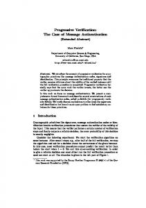
Figure 1: The flow of data from satellite to adversary to user, including signature generation, message encoding, propagation from satellite to user, decoding and signature assertion and direct observation of a subset of the received symbols. message can provide robustness against replay or relay attacks. Two case studies are examined, the Galileo E1B and the GPS L1C signals, both of which have a sufficient unallocated space in their respective navigation messages to host an NMA scheme, and both of which employ FEC. A hypothetical, generalized cryptographic message authentication scheme is assumed, which contains high entropy cryptographic data that is unpredictable to the attacker prior to its full recovery, but is uniquely identifiable once it, and its associated navigation data, have been fully recovered.
2.1
Message Authentication
Specifically, it is assumed that the navigation message, u, contains navigation data, d, which may be known prior to broadcast, and some cryptographic data, q, generated by the system via q = fSign (d), which is unknown prior to broadcast. A broadcast codeword, v then is generated from the navigation message, d and q, as: v = fEnc (u)
(1)
where fEnc represents the encoding and interleaving operations. In the case of E1B message this is a convolutional encoding and a 30 × 8 block interleaving, while for L1C, this represents an LDPC encoding and a 38 × 46 interleaving of two different subframes. Both cases effect a coding rate of 1/2, such that v is twice the size of u and the cryptographic content has been evenly spread across the codeword. Once symbols of this message are received at the target receiver, some form of decoding algorithm will be employed to recover the broadcast data: u ˆ = fDec (v) ,
(2)
where, u ˆ is the most likely navigation data, and fDec (·) may represent, for example, the Viterbi decoder in the case of E1B, or the sum-product decoder in the case of L1C. At the receiver, it is assumed that the function fAuth (·) exists which effects a simple test that asserts the authenticity of the navigation data: ( true if d is authentic fAuth (d, q) = (3) f alse otherwise.
2.2
Correlation-based anti-replay protection
The concept of correlation-based testing has emerged in the literature as a means of detecting certain forms of spoofing attack. Two techniques are possible, one operating at the spreading 3
code level, and the other operating at the symbol level [5]. Here we consider the symbol-level technique where the receiver implements a correlation over the first Tv seconds of each of a subset of size nq of the received symbols, v, denoted here by v ˇ. The signal energy observed over the period Tv is too low to reliably estimate the symbol value, but correlation over nq such periods is sufficient to observe the presence of the ensemble of symbols. In this case we imagine that the target receiver will implement a coherent integration to produce the vector of noisy samples: r=ˇ s + n, (4) where ˇ s is a bipodal sequence representing the correlation over the leading edge of the received realization security related symbols, v ˇ, with an amplitude corresponding to the received signal N0 . A test statistic energy, and n is a sequence of Gaussian noise, with variance given by: σn2 = 2T v is generated by performing the correlation with a bipodal realization of the samples of v ˇ ∈ [−1, 1]: X γ = rT v ˇ= ri vˇi . (5) i
In the case that the received signal is genuine, then γ should follow a Gaussian distribution given by: � � n q N0 , (6) γ ∼ N nq , 2CTv where C is the nominal received signal power. In the case that the signal is not genuine, and the symbols have been randomly chosen, then γ should be zero mean, and have a slightly increased variance, corresponding to the cross-correlation between ˇ s and v ˇ. To limit the exposure to an adversary who wishes to synthesize a counterfeit signal, a receiver may implement some sort of strict threshold on γ based on the expected received signal strength and some predefined false-alarm threshold. Essentially this would ensure that the cryptographic information contained in q was appropriately present in the received symbols, v ˇ, albeit corrupted by noise. We denote this test by fρ (·), as depicted in Fig. 1.
3
Receiver Vulnerabilities
Before trusting the position information provided by a receiver, it is beneficial to have some some idea of how reliable this information is. This concept has been well addressed in for the benign environment in the form of integrity monitoring, however, as yet, the study of more active malicious environments have not fully been explored. In the sections that follow, we offer an incremental examination of some of the threats a receiver may face. If a genuine GNSS signal contains unpredictable data, it has been suggested that the most likely attack methodology is that of the security code estimation and replay (SCER) attack [5, 11]. In such an attack, the adversary must observe each of the genuine signals which are to be replicated, estimating the value of each of the security-related symbols, and using this information to synthesize the counterfeit signals. These signals must also be observed at a high signal-to-noise ratio, as the symbol estimation might be conducted having only observed a short portion of each received symbol. A number of methods of effectively estimating and synthesizing the security-related symbols have been presented [5] and it has been further claimed that the presence of cryptographic content places some constraints on the effectiveness of a SCER attack [4, 5]. In particular, results have been provided which suggest that a counterfeit signal can only be generated at a non-negative delay relative to the genuine signal. The tradeoff between the delay and the likelihood of correctly replicating the security-related symbols, and its dependence on the relative signal-to-noise ratio experienced by the adversary and target, has also been presented [5].
3.1
Forward Estimation Attack
This SCER approach has considered each of the navigation symbols as independently being known or unknown, and has not considered the interdependence introduced by the coding process. In reality, elements of the codeword v are not independent, and values of v are quite sparse. 4
d
𝑓123# 𝒅 u = [d,q]
𝑓"#$ 𝒖 v SV-to-adv. channel
FEA
adv.-to-user channel
observe vk-1 and predict vk
C 𝒗
𝑓&'$ 𝒗) C 𝒖 𝑓*+,- 𝒅, 𝒒
Authentic: true/false
Figure 2: The flow of data from satellite to adversary to user under a spoofing attack, including signature generation, message encoding, propagation from satellite to user, decoding and signature assertion. It is this redundancy that supports error correction, however it can also be exploited by an adversary to facilitate an attack. In fact, under ideal conditions, it is only necessary to recover half of the broadcast symbols to fully recovery the navigation message, the remainder is redundant. Because of the redundancy and interdependency provided by FEC, given a small portion of the broadcast codeword, v, each subsequent symbol can be predicted with a better than 50% accuracy. The more symbols are received, the better this prediction accuracy becomes. This saturates once half of the symbols are received (under 1/2-rate encoding), at which point subsequent symbols can be predicted with 100% accuracy. Naturally, this process is enhanced when some of the navigation data, u, is a priori known, and the number of symbols which must be recovered for a given prediction accuracy reduces accordingly. At the target receiver, these symbols are recovered and fed to the decoding function, fDec (·), to decode the navigation message. Provided that a sufficient portion of the received symbols are correct, the decoder will return the genuine navigation data u, and the authentication test, fAuth (·), will pass. Naturally, it is not possible that an adversary might perfectly re-broadcast valid symbols before they have ever been received, but given some a priori knowledge of u, it is possible for an adversary to predict successive symbols of v, before they have been received, with a reasonably high accuracy. As each new genuine symbol is received, the accuracy of subsequent predictions increases in a deterministic, but not necessarily monotonic, manner. The exact accuracy is dictated by the coding scheme and the portion of u that is known. Thus, an adversary can reliably synthesize counterfeit GNSS signals which will appear genuine to the target receiver. Unlike the SCER attack, it is not constrained by a prompt estimation of each symbol as it is broadcast. Moreover, this methodology, termed a forward estimation attack (FEA), allows an adversary to produce counterfeit signals at both a delay and an advance relative to the genuine signal. A simplified depiction of the actual transfer of information is presented in Fig. 3. The sequence of symbols labeled (a) depicts the transfer of information to the adversary, wherein only the first half of the symbols contain information. The sequence labeled (b) depicts the information content of the symbols generated by the adversary and broadcast to the target. In this case the first symbols are random and contain no information, as the adversary has not yet recovered any from the genuine signal, the next portion contains the majority of the genuine message information, and the final portion are mostly redundant. Note that the effective redundancy has reduced in proportion to the signal advance, which in this case is three symbols. Finally, the sequence labeled (c) depicts the information content that is perceived by a na¨ıve receiver, which assumes that each
5
Information
Redundancy
Random Symbols
(a) (b) (c) Time
Figure 3: Information transfer in encoded symbols: (a) flow of information from satellite to adversary, (b) flow of information from adversary to target, (c) perceived reception of information by target. symbol contains 1/2-bits of information. Under this scheme, some symbols can be more accurately estimated than others, depending on where in the navigation data they are, and how much of the symbols can be recovered prior to their estimation. To improve the effectiveness of this attack, the adversary may weight the re-broadcast symbol based on the probability that it is correct. This de-weighting may be in the form of a reduced broadcast power and, depending on the target decoder configuration, may result in a reduced weighting of the corresponding symbol in the target decoder. The target, upon receiving the counterfeit signal, will experience a binary symmetric channel (BSC), where some symbols may have been incorrectly estimated by the attacker. By applying an optimal decoder, the target receiver will attempt to reconstruct the most likely broadcast symbols, under the assumption that any symbol errors experienced have been induced by thermal noise. Having recovered the navigation data, u, the message data and cryptographic content, d and q, respectively, and the authenticity of the message can be asserted. An attack is considered successful if fAuth (d, q) evaluates to true for a counterfeit signal. The probability of this occurring depends on two factors: the subset of symbols that are incorrectly guessed by an adversary; and the weighting that the target receiver applies to these symbols. Through appropriate synthesis of a counterfeit signal, an adversary might manipulate the target decoder to reduce the emphasis on symbols that are likely to be incorrect. In such a scenario, the adversary may be aware that the target receiver implements soft-decoding, and may have knowledge of it’s configuration. A variety of receiver configurations are considered here, ranging from a hard-decision decoding to various degrees of soft-decision decoding where, in each case, the adversary has knowledge of the receiver configuration, and may synthesize counterfeit signals accordingly. In the following sections, the vulnerability of signals employing either convolutional encoding or LDPC to the FEA will be shown. Regarding notation, in the expressions that follow, in particular when discussing the vector of symbols, v, the interleaving and deinterleaving operations have been omitted for the sake of clarity. In reality, v is not filled in a linear fashion with time, from top-tobottom or from left-to-right, but rather is filled according to the interleaving matrix. Despite the omission in the notation the results presented here take account of the 30 × 8 interleaver on E1B and the 36 × 48 interleaver on L1C.
3.2
State modeling attack
As discussed in the previous section, under a successful forward-estimation attack, the target receiver will decode a valid sequence navigation data despite not having received the genuine navigation symbols from the satellite. An adversary might exploit this to synthesize counterfeit GNSS signals without having to first observe them. Although the adversary might predict sufficiently many navigation symbols such that the target receiver is oblivious to the attack, not all symbols can be predicted. The target receiver may leverage this fact in an attempt to protect itself from the adversary, by implementing a correlation-based signal verification [10]. This section will demonstrate a means by which an adversary can generate counterfeit signals, including those symbols which are unpredictable, such that a counterfeit signal will still pass the correlation-based verification. In this approach the adversary will generate each spoofed symbol without attempting to first observe the corresponding genuine symbol.
6
This attack exploits three features of a symbol-level correlation based verification test: 1. Once the leading edge of each unpredictable symbol has been captured by the target receiver, the genuine value of that symbol is disclosed. This implies that when the k th symbol, vˇk must be guessed by the adversary, all previous symbols, [ˇ v0 · · · vˇk−1 ], are known. 2. Correlation is an additive process, and so the statistic, γ, used in the correlation-based verification test cannot distinguish between energy accumulated in one symbol or another. It only observes the energy captured in the ensemble of symbols, regardless of which symbols contributed energy. 3. As the energy captured in the leading edge of each symbol is very low, and the signal-tonoise ratio of each symbol measurement is very small, the target receiver cannot detect variations in the instantaneous receiver power during that symbol. Thus, the adversary is free to modulate the instantaneous power in each spoofed symbol, within a certain range. The attack is based on exploiting the knowledge extracted from the previously broadcast symbols, [ˇ v0 · · · vˇk−1 ], in the generation of the next spoofing symbol, sk . Naturally, given a sequence of unpredictable symbols, knowledge of one symbol cannot aid in the prediction of the next, however, this does not mean that it contains no useful information. The release of each symbol allows the adversary to determine how many of the previous spoofed symbols were guessed correctly. The adversary can compute a running model, γˆ of the internal state of the target receiver at each epoch k, estimating what value γk will take: γˆk−1 =
k−1 X
sˇi vˇi .
(7)
i=0
This is done knowing what symbols should have been received, [ˇ v0 · · · vˇk−1 ] and what spoofed symbols were actually sent, [ˇ s0 · · · sˇk−1 ]. In the case of the genuine signal, then all symbols will be correct, and the expected value of γ will be equal to k, in units of signal energy. In the case that a spoofed symbol, sˇk−1 , was guessed in error, then the model γˆk−1 will be below this expected value and so the adversary can increase the energy of the subsequent symbol, sˇk in an effort to compensate. If it transpires that sˇk is guessed correctly, the value of γˆk−1 will be restored. If it is not, then the compensation has been applied in the wrong direction, and the energy of the next symbol, sˇk+1 , must be increased further. With each consecutive symbol that the adversary guesses incorrectly, the power required to restore γ doubles, and so the distribution of the amplitude of the spoofed symbols will be exponential. Of course this is not practical as: i) the presence of very large signal amplitudes, however infrequent, will be detectible by the target receiver, and ii) the target receiver will have a limited dynamic range, bounded primarily by the finite resolution of the digitizer. A practical attack will therefore bound the amplitude of the spoofed symbols to some level which is deemed undetectable by the target yet sufficiently high to induce the appropriate adjustment of γ. It is noteworthy that this style of attack results in random-walk of the target receiver’s computation of γ and so the attack does not have a deterministic rate of success, even in the absence of thermal noise. Despite these limitations, as will be shown in the subsequent sections, this state-modeling attack can achieve a very high probability of success, rendering correlation-based signal verification, when computed over the leading edge of message symbols, relatively ineffective. By analogy to the St. Petersburg Paradox, we see that the scheme offers a distinct advantage to the adversary [12].
4
Attack on Convolutional Codes
To successfully compromise a target receiver via an FEA, the adversary must find an effective manner to exploit a priori knowledge of part of u in conjunction with the recovered portion of v, to accurately predict the future symbols. For the case of convolution encoding, this process has been demonstrated using a modified Viterbi decoder. The E1B signal is encoded in pages of 120 bits using a 1/2-rate convolutional encoder of constraint-length 7, as depicted in Fig. 4. Of the 120 bits broadcast, 40 bits of each odd page
7
G1
u
z-1
z-1
z-1
z-1
z-1
v
z-1 G2
Figure 4: Convolutional encoding used in the generation of the E1B signal. G1 and G2 represent the generator polynomials and z −1 denotes the unit delay.
u0
u1
u2
u3
u4
known transition: u3 = 0
Transition to 0 Transition to 1
Figure 5: Modified Viterbi decoder which constrains certain transitions based on a priori knowledge of u. In this example, u3 is known to be 0. are, as yet, unallocated [8] and are suitable for use in an NMA scheme [2, 4, 13], and represent the cryptographic data, denoted q. The remaining 80 bits of the message might contain noncryptographic data, d, and can therefore be assumed to be known. To compromise such a scheme, and to synthesize a counterfeit signal with a k-symbol advance, the adversary would attempt to predict the nth symbol, vn , of v, given the a priori data, d, and the portion of the symbols, (v0 , ..., vn−k ), that have already been received. In the FEA approach that follows, after the reception of each new symbol, vn−k , the adversary aims to first recover the most likely value of u, and then re-encode this to form the most likely value of v, and select from this the nth symbol, vn , to transmit to the target. This involves a decoding of the partially received symbols, followed by an encoding of the most-likely data, one for each new symbol that is received by the adversary. Note that one drawback of this approach is that the codeword, v, that is sent is not guaranteed to be coherent as it is, in effect, the encoding of a continuously changing u.
4.1
The modified Viterbi algorithm attack
The problem of prediction of future symbols of the navigation message, based on a partial observation of the encoded symbols can be viewed as transmission through a binary erasure channel (BEC), where some of the symbols are known to be either 0 or 1, while others are known to be erased, and are denoted e. The process of recovering data across a BEC using a Viterbi decoder is similar to the more common hard- or soft-Viterbi decoding algorithm [14–16], with the exception that erasure symbols, do not contribute to their corresponding branch metric. In general, provided there are few erasures, and that they are sufficiently sparse, then u can be recovered. To exploit a priori knowledge of the navigation data, u (the non-cryptographic part, d), a modified Viterbi decoder has been developed. This decoder constrains the set of possible paths through the decoding trellis based on each known bit un , forcing a certain set of transitions. This process is depicted in Fig. 5, where the element u3 is known to be 0, and all possible paths
8
through the trellis follow the upper branch. This has the effect that for each known bit of u, rather than doubling the number of subsequent candidate paths, the number of paths remains the same. Not only does this provide improved decoding in the presence of additive noise, it provides a local constraint on the paths even when the corresponding symbols are erasures, the result is a significantly improved data estimation performance. The basic principle of the Viterbi-based attack is that the adversary observes the stream of symbols as they arrive from the satellite as a BEC, where all symbols that have not yet arrived can be considered as being erased. This partially received set of symbols is denoted by: � �T v ¯ = v0 v1 ... vn−k e e ... e e e e , The adversary must then reconstruct the most likely broadcast data, u ˆ , aided by a priori knowledge of some of the broadcast data. This is done using a modified Viterbi decoder, which is constrained by d: Viterbi u ˆ = fDec (¯ v, d)
(8)
The best estimate of the current set of broadcast symbols can then be determined by re-encoding this data: v ˆ = fEnc (ˆ u)
(9)
At the k th spoofed epoch, the adversary will then select the appropriate element, vˆk , from this set of symbols, and use it to synthesize the spoofed signal.
4.2
The overdetermined system attack
This section will discuss a second method of attacking the convolutional-encoded signal by inverting the encoding operation defined by the generator polynomials. Examining the encoding method, the relationship between each coded symbol and a subset of the data u can be expressed as:
v2n = un + un−1 + un−2 + un−3 + un−6 v2n+1 = un + un−2 + un−3 + un−5 + un−6 + 1
(10)
Because a large portion, d, of the navigation data, u is known, and new elements of v are continuously being received, it is possible that one instance of the generator equations, (10) contains only one unknown element of u. In this case, the value of the unknown element of u can be determined. Once an element of u has been resolved, there is a possibility that another instance of (10), corresponding to another value of n, can be solved. This concept can be extended to a system of equations in multiple unknowns. Once the system of equations has been solved for u, it can be encoded to produce the most likely value of v, from which the next symbol to broadcast to the target can be selected. As each new element of v is received, the process can be repeated. Solving for u in this manner, although requiring a dedicated implementation, can be more efficient that the implementation of a full Viterbi decoder. To obtain the system of equations, we must reformulate the problem in matrix form. This produces an overdetermined system of linear equations over the binary field, GF (2), and is given by: H.u = v,
(11)
where u is the data to be encoded, v is the set of coded symbols, and H is the encoding matrix, consisting of shifted copies of the polynomials (10). For E1B, blocks of 120 bits of data are encoded and so these matrices are quite large: u is 120 × 1, v is 240 × 1, and H is 240 × 120. However, as the region of influence of each bit on the corresponding symbols is bounded by the constraintlength of the code, the encoding matrix will be particularly sparse and very regular. Exploiting
9
this fact, the problem can be restricted to the sub-matrix, H0 , spanning a small number of bits in the message. For example, the local encoding process can be expressed by the following 14 × 13 encoding matrix, given by: 1 1 1 1 0 0 1 0 0 0 0 0 0 1 0 1 1 0 1 1 0 0 0 0 0 0 0 1 1 1 1 0 0 1 0 0 0 0 0 0 1 0 1 1 0 1 1 0 0 0 0 0 0 0 1 1 1 1 0 0 1 0 0 0 0 0 0 1 0 1 1 0 1 1 0 0 0 0 0 0 0 1 1 1 1 0 0 1 0 0 0 (12) H0 = 0 0 0 1 0 1 1 0 1 1 0 0 0 0 0 0 0 1 1 1 1 0 0 1 0 0 0 0 0 0 1 0 1 1 0 1 1 0 0 0 0 0 0 0 1 1 1 1 0 0 1 0 0 0 0 0 0 1 0 1 1 0 1 1 0 0 0 0 0 0 0 1 1 1 1 0 0 1 0 0 0 0 0 0 1 0 1 1 0 1 1 and H0 .u0 = v0 , 0
(13) 0
where v represents a block of 14 consecutive encoded symbols, and u represents the 13 bits on which these symbols depend. The problem of predicting a symbol can then be expressed as solving, partially or fully, the system of linear equations defined by (13), for u0 and encoding the result to find elements of v0 . We may then arrange u0 and v0 such the symbol we wish to predict falls within v0 . Note that for any given symbol, there will be 7 different arrangements which ensure this. Next we can reduce the set of equations by eliminating rows of H0 which do not constrain u0 , to produce a system of equations describing a sub-space of (13): H00 .u00 = v00 ,
(14)
To produce (14) from (13), firstly the rows of H0 corresponding to unknown elements of v0 are eliminated. Secondly, rows of H0 which multiply all unknown elements of u0 by zero are eliminated (i.e. those which produce an element of v0 which does not depend on any unknown element of u0 ). Finally, columns of H0 which contain only zeros are eliminated. The result is a significantly reduced system of linear equations over GF (2). A solution for u00 can then be used to determine v00 and, in turn, v. However, it is not guaranteed that (14) will have a unique solution, and only a unique solution will yield the correct value of v. What is particularly interesting is that, because a large portion of the navigation message is known, the number of unknown elements of u00 is quite small, for example, being four bits or fewer. Therefore, a brute-force check of all possible permutations of u00 in this search space can be performed. Via an exhaustive search, the uniqueness of a realization of u00 which satisfies (14) can be asserted. The exact number of symbols that are required to uniquely identify a set of bits can be obtained via examination of (13). Taking an arbitrary example, we assume that only the last four bits of u0 are unknown: � �T u0 = u0 u1 u2 u3 u4 u5 u6 u7 u8 ? ? ? ? , and wish to determine which symbols must be received to decode them. Noting the positions of the zeros in (12) it is clear that only the last eight elements of v will depend on the last four elements of u0 , such that it does not matter whether or not the first six symbols have been received, and are therefore denoted by ‘−’: � �T v0 = − − − − − − v6 v7 v8 v9 v10 v11 v12 v13 , Of these eight elements, a subset of only four is sufficient to uniquely identify u0 , however, � due to the nature of GF (2) arithmetic, it is not true that any four will suffice. Of the 84 = 70 10
combinations of four symbols that can be selected from these eight, it transpires that a total of 37 combinations will uniquely identify u0 . Similarly, if only the last two symbols of u are unknown, then only two of the last four elements � of v are required to decode them, where 5 of the 42 = 6 combinations of two symbols will suffice. This represents a relatively relaxed constraint and, as will be shown next, results in a very high likelihood of decoding u0 . The system of linear equations, (13) can then be shifted along the vectors u and v to form the next value of u0 and the process repeated: a system-reduction followed by a brute-force check. This can be iterated until no more unique solutions for u0 can be found, at which point no more information can be extracted from the partially received set of symbols, v. It is important to note that as more values of u are found, the more values of v can be identified, and the unknown values of u become more sparse. The result is that the size of the brute-force check in subsequent iterations is reduced. Monte-Carlo trials for the particular case of E1B, assuming that 32 bits of the navigation message are unknown, show that this approach requires 8 iterations of a brute force search over 4 bits for each received symbol. To illustrate how simple this task is, the operation is equivalent to 128 multiplications over GF (2) of a 14 × 13 matrix by a 13 × 1 vector, followed by a 14-element binary comparison. This must be completed once every 4 ms, which is a trivial task.
4.3
Exploiting the CRC
When assessing the encoding of the navigation message it is important to consider the effect of any further layers of redundancy in the data. In the case of GNSS, it is common to add a cyclic redundancy check (CRC) to blocks of broadcast data, as in the cases of both Galileo E1B and GPS L1C. Because this CRC is a function of q it represents an advantage to the adversary, essentially reducing the effective coding rate to slightly less than 1/r (being equal to 2/5 for the odd pages of Galileo E1B). In the attacks presented here, there is an inherent relationship between q, the CRC, and the navigation data, d. Given a partially recovered message, a brute force-search on a small number of remaining bits was performed observing the CRC-check as confirmation that the correct bits had been found. This causes the remaining entropy of the message to collapse, and provides a corresponding increase in the probability of successful attack. For Galileo E1B, a 24-bit CRC is used, and so once the number of unknown bits of q fell below 24, a brute-force search was conducted. Of course, as the CRC itself had not been recovered, the consistency check was made against received navigation symbols. The procedure was as follows: i) choose a candidate realization of the unknown bits of q ii) compute the corresponding CRC iii) encode this candidate message iv) compare the encoded symbols with the subset of symbols already received. Depending on which, and how many symbols have been received, the partial symbol-domain check may not provide a unique solution, however when it does it immediately resolves the remaining bits of q, thereby rendering the entire message known. It is further possible, although not explored here, that the CRC itself might be inverted to more explicitly constrain q. In such a case, it would likely provide a more efficient solution, requiring knowledge of fewer symbols to identify q. What is significant about this, however, is that it provides multiple sources of information relating to q, being any of the symbols which are a direct result of the encoding of the q, or any of the symbols which are a result of the encoding of the CRC. The adversary may exploit a subset of both.
4.4
FEA on Galileo E1B
In this case an idealized cryptographic scheme has been assumed which inserts a total of 32 bits of data into every second page of the I/NAV message. Specifically, it is assumed that: the last 32 bits of each ‘Reserved 1’ field [8] of the odd pages are occupied with cryptographic content; and that the remaining data bits are fully known in advance to an adversary. Fig. 6 presents simulation results considering an FEA attack on a target receiver which processes the E1B signal using a soft-decision Viterbi decoder. Five different weighting values have
11
Prob. Successful Attack
100
10-1
10-2
w = 0.0625 w = 0.1250 w = 0.2500 w = 0.5000 w = 1.0000
10-3
10-4
5
10
15
20
25
30
Symbol advance
Figure 6: Probability of a successful forward-estimation attack generated via Monte-Carlo simulation of a target receiver. The trials consider a range of symbol advances, and a variety of decoder architectures including hard-decision Viterbi (w = 1.0), and a selection of SOVA decoders with varying reliability quantization (w = {0.0625, ..., 0.5}). been considered: w = {0.0625, 0.125, 0.25, 0.5, 1.0}, being equivalent to a hard-decision decoder, and two- to five-bit digitization in a soft-decision decoder. For each of these cases, the probability that a successful attack can be conducted is assessed as a function of the signal advance. In this case, the attack based on the overdetermined system of equations has been selected. It is clear that as the degree of de-weighting is reduced, the probability of success reduces, to the point where a hard-decision decoder appears to be relatively invulnerable. Also, the fact that the encoding interleaver operates on a 30 × 8 matrix, appears to constrain the attack to an advance of no more than thirty symbols. Nonetheless, it is evident that a target receiver which employs soft-decision decoding over four or more bits can be compromised with a very high probability of success, in this case greater than 90% for a four-bit decoder, and 100% for a five bits or higher. The extent of the delay seems not to affect the probability of success and can reach 116 ms, equivalent to a range change of approximately 34,800 km. For context it is worth recalling that the probability success given a blind guess of the cryptographic content is 1/232 ≈ 2.3 × 10⁻¹⁰ , which is many orders of magnitude lower than what can be achieved even considering even the worst-case of the hard-decision decoder, ≈ 1.0 × 10⁻² .
4.5
Identifying the symbols of interest
A degree of protection against the broadcast of counterfeit signals can be provided by implementing two tests on the received signal: the navigation content can be tested for authenticity, via fAuth (·); and the correctness of each of the received symbols can be asserted, via fρ (·). The first test may ensure that the message originated at the satellite. The second test can ensure that it is difficult for an adversary to receive and rebroadcast genuine signals, by asserting that those symbols which cannot be predicted are correct. The combination of these two tests might represent a barrier to a malicious adversary. Here we aim to identify which elements of v are unknown from the perspective of this adversary. Specifically, we might identify a subset, v ˇ, of v, which contains the symbols that are unpredictable by the adversary at the time they are transmitted. Then we might assert that the data is authentic, via fAuth (·), and simultaneously assert via some other function, fρ (·), that all symbols were correctly received. Ideally we should select the subset v ˇ to be as small as possible, while containing all of the information instilled by q. In principle, the smallest such size should be equal to the number of bits of q.
12
To select v ˇ we might examine Fig. 13. Noting that the set of symbols unknown at an advance of i symbols is a subset those unknown at an advance of i + 1 symbols, we might select v ˇ to be those symbols unknown at an advance of i = 1. In particular, we must ensure that no forward estimation attack exists which results in a set of unknown symbols which is orthogonal to our selection of v ˇ. In the event that such a scheme exists, and that an adversary may predict some or all of v ˇ, but leave other symbols, not asserted by our test, unknown, then then scheme might be compromised. Intuition suggests a unique realization of v ˇ equal in size to q should exist, and that should be a function only of the coding scheme, and not of the attack scheme. If the cryptographic data, q, is of size nq bits, then given d it should only take nq bits to describe v. More specifically, the entropy of q should be equal to the conditional entropy of v, given d, and to that of our candidate subset v ˇ, given d: H (q) = H (v|d) = H (ˇ v|d) = nq .
(15)
Under the conservative assumption that the coding scheme distributes information evenly across d, then as each symbol is received by the adversary, the residual uncertainty of q diminishes: H (ˇ v|d, v0 , v1 , · · · , vk−1 ) ≤ H (ˇ v|d, v0 , v1 , · · · , vk ) ,
(16)
where inequality holds if vk is dependent on q and equality holds otherwise. Thus, we might select our candidate subset, v ˇ, to be the first nq elements of v that are dependent on q. Taking the E1B example, and assuming that last nq = 32 bits of the ‘Reserved 1’ field of the I/NAV message contain q, we might identify the subset to test. Note that in this case, the CRC is computed over the entire page, including the ‘Reserved 1’ field, which spreads this information further throughout the coded symbols. Thus the symbols of interest will be the earliest 32 of those which are dependent on either q or the CRC. Considering the encoding and interleaving process, then the subset of symbols that should be tested, indexed according to their interleaved form would be: v ˇ = [v8 · · · v16 , v22 · · · v28 , v38 · · · v46 , v52 · · · v58 ] , (17) as depicted in Fig. 7. For convenience, this can be expressed in terms of the de-interleaved symbol index: � v ˇ = v57 , v58 , v65 , v66 , v73 , v74 , v81 , v82 , v89 , v90 , v97 , v98 , v105 , v106 , v113 , v114 , v121 , v122 , v169 , v170 , v177 , v178 , v185 , v186 , � v193 , v194 , v201 , v202 , v209 , v210 , v217 , v218 .
(18)
It is important to note that the inclusion of the cryptographic data in the CRC has a significant effect on v ˇ. In fact, the set of symbols that would be unpredictable to an adversary were q not included in the CRC would only overlap with (17) by 50%. Moreover, the process of interleaving serves to bring information borne on CRC related symbols forward in the broadcast message, stripping some for the q related symbols of their entropy.
5
Attack on LDPC Codes
This section will provide an overview of LDPC coding and will provide details of a possible attack on LDPC codes, which can enable the synthesis of symbols in advance of the reception of the genuine signal. When encoding a sequence u using an LDPC encoder, a generator matrix, G, is found such that the non-systematic portion of the codeword, denoted here by s, is computed via: s = Gu
13
(19)
1 0.8 0.6 0.4 0.2 0 0
10
20
30
40
50
60
Symbol Index
Figure 7: Locations of the subset of symbols, v ˇ, that might be tested by a receiver to identify a potential spoofing attack. over GF (2). The codeword is then formed as the concatenation of the systematic and nonsystematic components: v = [u s] .
(20)
This codeword is then modulated directly onto the broadcast signal for transmission. At the receiver, once the codeword has been recovered, a checksum can be computed, to detect the presence of symbol errors, via: c = Hv. (21) In the case that an adversary wishes to predict future symbols of the codeword, the checksum equation, (21) can be used. By design, the checksum matrix H is sparse, and each row of H has only a few non-zero elements. As such, each element of c depends on very few elements of v. Noting that the upper half of v, is the original data sequence, u, some of which, d, is known a priori, as each new element of v is received, there is a chance that an element of c depends on only one unknown element of v. In this case, knowing that c should evaluate to zero, we find a single equation in one unknown, and so the element of v can be resolved. Interestingly, once this element of v is resolved, it may render another element of c dependent on only one unknown symbol of v, producing another single equation in one unknown. And, thus, the process can recurse. This iterative solving of single binary equations can be repeated as each new symbol is received, until the full codeword is known.
5.1
Solving the Checksum Equations
To implement an FEA attack on an LDPC encoded signal, it is necessary to recover the portion of the codeword, v that has not yet been received. This is distinct to the case of the convolutional coded signal, where the data, v, was first recovered, and re-encoded to produced v. In this case, the checksum equation, (21), operates directly on the broadcast symbols. The first step in finding a partial solution to (21), is to identify which portions of the matrix can be solved. This can be done by populating a candidate symbol vector, v ¯, comprising of the known data, d, and the symbols which have already been received: � �T v ¯ = v0 v1 ... vk−1 e e ... e e e e ,
(22)
where some of the elements vk may represent data already known, being some of the systematic portion of the codeword, or may be freshly received symbols being either systematic, or nonsystematic elements. Next, a population vector, p, can be constructed, which contains 1 in the elements where the corresponding value of v ¯ is known, and contains 0 otherwise: � �T p = 1 1 ... 1 0 0 ... 0 0 0 0 .
14
(23)
Computing the product H (1 − p) over N, rather than GF (2), will indicate the number of unknowns for each linear equation. Those rows which evaluate to 1 are of the rows of H which result in a solvable checksum. A mask of the solvable checksums can then be defined as: m := {H (1 − p) = 1} ,
(24)
which is a binary vector containing 1 at the locations of v ¯ that are solvable, and 0 otherwise. Thus, at each iteration, k, the vector of partially received (and partially solved) symbol vector, v ¯, can be updated by computing: v ¯ := v ¯ + mH¯ v.
(25)
over GF (2). In essence, this operation masks the elements of v ¯ which are solvable, via (24), and adjusts the value based on the checksum computation, (21).
5.2
FEA on GPS L1C
This section examines the case of the GPS L1C signal, considering that a message authentication scheme might be implemented using the unallocated fields of the navigation message. Specifically, it is assumed that the 87 bits, located in the ‘Reserved’ field from bit 164 to bit 250 of Subframe-3, Page-5 are used [9]. It is assumed that these bits are occupied with unknown cryptographic data, and that the remaining data bits are fully known in advance. Fig. 8 presents results considering an FEA attack on a target receiver which processes the GPS L1C signal using a sum-product decoder. Again, five different weighting values have been considered: w = {0.0625, 0.125, 0.25, 0.5, 1.0}, and for each of these cases, the probability that a successful attack can be conducted is assessed as a function of the signal advance. Note that a number of the points corresponding to the hard-decision decoder are omitted, as Monte-Carlo simulations are still being run. Unlike the previous case, the probability of successful attack varies smoothly with both the signal advance and the symbol weighting. Also, owing to the nature of block-codes, the duration does not seem to be directly influenced by the interleaving size, and very large signal advances can be sustained. It is clear that when the symbol weighting is increased by beyond 0.25, the attack success rate is approximately 100% for signal advances up to 10 symbols, or 100 ms, equivalent to a range change of approximately 30,000 km. Again, it is worth noting that the probability of successful attack given a blind guess of the cryptographic data would be 1/287 ≈ 6.5 × 10⁻²⁷ , which is, again, many orders of magnitude lower than what can be achieved even considering the worst-case of a hard-decision decoder, ≈ 1.0 × 10⁻² .
6
State modeling attack on correlation-based verification
As we have seen, it is possible for an adversary to generate a counterfeit GNSS signal which is sufficiently accurate that a receiver is likely to extract from it a valid navigation message, for which the data authenticity test is successful. Although the target user may still be confident that the navigation data is genuine, this confidence does not extend to the position domain. For this reason the target user may implement further tests, which focus on the limited extent to which the counterfeit signal is accurate. Specifically, the test will focus on those symbols of the message which cannot be accurately predicted. As these symbols are openly broadcast, the user must design a test which is sensitive to the symbol before it becomes fully known to the adversary. This is done by capturing samples of the signal along the leading edge of these symbols, for a period of time which is too low for the adversary to accurately estimate the symbol value. Naturally, this period will also be too short for the user to determine the symbol value from these symbols, and so a correlation-based test is applied to the samples. As described in (5), the user will capture a sequence of noisy samples and compute the test
15
Prob. Successful Attack
100
10-1
10-2 w = 0.0625 w = 0.1250 w = 0.2500 w = 0.5000 w = 1.0000
10-3
10-4
5
10
15
20
25
30
35
40
45
50
Symbol advance
Figure 8: Probability of a successful forward-estimation attack generated via Monte-Carlo simulation of a target receiver. The trials consider a range of symbol advances, and a variety of decoder architectures including the simplified sum-product decoder (w = 1.0), and a selection of variations of the log-likelihood decoder with varying reliability quantization (w = {0.0625, ..., 0.5}). quantity: r=ˇ s+n γ = rT v ˇ=
(26) X
ri vˇi ,
(27)
i
from which some verification may be made via: ( true, for|γ|2 ≥ VT , fρ (q, r) = false, otherwise
(28)
where VT is a threshold chosen based on the expected received signal strength and desired falsealarm rate. Note that the square magnitude of γ is tested [5], however, in the event that phasecoherence was provided by the receiver, the test may simply examine < (γ), which may provide improved selectivity. This section examines a means by which an adversary would attack a receiver which implemented the test described by (28), without the need to observe the genuine symbol prior to transmission of the corresponding counterfeit one. It must be stressed here that this is not a SCER attack, as there is no need for the adversary to attempt early estimation of each symbol. Instead, each counterfeit symbol is generated based only on the observation of the previous genuine symbols.
6.1
Algorithm Description
Here, we consider an algorithm by which the adversary will generate the sequence of spoofed symbols, ˇ s, such that the test (28) passes. The key to this algorithm is that when generating the k th spoofed symbol, sˇk , the adversary has knowledge of all of the previously released unpredictable symbols, [ˇ v0 , · · · , vˇk−1 ] along with the set of spoofed symbols that were sent to the adversary, [ˇ s0 , · · · , sˇk−1 ]. Given this information, it is possible to compute a running model of what the internal state of the target receiver. At the k th epoch, a model of the running calculation γ can be given by: k X γ¯k = sˇi vˇi , (29) i=1
16
Symbol
10 5 0 -5 v5k
s5k
-10 0
32
64
96
128
160
192
224
256
96
128
160
192
224
256
.k Evolution
300 .7 .Nominal .Spoofed
200 100 0 0
32
64
Symbol Index; k
Figure 9: The realization of the genuine and spoofed symbols, vˇk , and sˇk , normalized to units of nominal signal amplitude are shown in the upper subplot. Note that when a spoofed symbol is estimated incorrectly, the subsequent symbols is increased in amplitude. The lower subplot shows the evolution of γ, including the state model γ¯ , the value computed by the target for a genuine signal, γNominal , and the value computed by the target for a spoofed signal, γSpoofed where the model is arbitrarily normalized to units of signal amplitude. In the case that the signal were genuine, or that the adversary correctly guessed all symbols, then sˇi = vˇi and the summation is equal to k − 1. In the case that some symbols were guessed in error, then the summation will be reduced. The adversary can use this estimate to drive the choice of the subsequent counterfeit symbol. Of course, this information will not help in choosing the polarity of the symbol, but can be used to select an appropriate amplitude. In the case that γ¯k is too low, then the adversary may increase the amplitude of the subsequent symbol, and make a random guess as to the polarity. If the guess is correct, then γ¯k and therefore γk is restored. If this guess is incorrect, the error in γ¯k will grow, and the amplitude of the next symbol must be increased further, to compensate for the previous two errors. Specifically, the amplitude of the k th symbol, denoted here by αk , may be chosen based on the deficiency of γ¯k : δγk = γ¯k − k
(30)
αk = δγk−1
(31)
sˇk = (1 + αk ) v¯ˇk ,
(32)
where v¯ ˇk represents the adversary’s estimate of the next symbol which, in this case is a random guess of ±1, with a probability of error, Pe = 0.5. While evolving, consecutive incorrect values of v¯ ˇk will cause the amplitude, αk , to grow exponentially, however the probability of it growing over k epochs is proportional to Pek , which will decay exponentially. Note that the k th symbol is synthesized only using information extracted from previous symbols, thereby eliminating the need for early symbol estimation. The principle of operation of (32) is that the error in polarity of the synthesis of one symbol is compensated by an increased amplitude in the subsequent symbol. A proportional correction, αk , is applied based on the difference between a set-point, k, and an integrated state, γˆk . This takes the form of a closed-loop rate-feedback controller with the important distinction that the direction of the correction depends on whether or not v¯ˇk is correct. If it is correct we effect negative-feedback control, which is stable, but if it is incorrect we effect positive-feedback, which is unstable. This is a chaotic process which randomly dithers between a stable and unstable system. Interestingly, as Pe is reduced, this system converges to a deterministic negative-feedback proportional controller. 17
Table 1: Overpower limit in dB for different digitizer resolution (B) at various received C/N0 levels, assuming a pre-digitizer bandwidth of 10 MHz. C/N0 (dBHz) B 51.0 48.0 45.0 42.0 1 18.0 21.0 24.0 27.0 2 23.2 26.1 29.2 32.1 3 24.5 27.2 30.5 33.4 4 25.1 27.6 31.1 34.0 5 25.4 28.4 31.3 34.2
An example of the time-evolution of this attack is shown in Fig. 9, wherein the upper figure depicts both the genuine and spoofed broadcast symbols, and the lower figure depicts the evolution of γ. Notice that when a symbol has been incorrectly estimated, the subsequent calculation of γ¯ shows a deficiency, and so the following symbol is doubled in amplitude. Shown also in the lower figure is the target receiver computation of γ, which includes thermal noise, for both a genuine signal and a spoofed signal. In this particular example, a sample rate of 10 MHz, complex, has been selected, the prevailing C/N0 was chosen to be 48 dBHz, and the leading 2 µs of each of 256 chips were accumulated.
6.2
Increased signal amplitude
To drive the internal state of the target receiver to the desired level, the adversary must increase the broadcast power of the spoofed signal, corresponding to the leading edge of some of the symbols. According to (32), with each consecutive incorrect guess of the the symbol, the amplitude of the subsequent must be doubled. Given a probability of error, Pe , for the guess of the next symbol, then the amplitude of the spoofed symbols will follow a geometric distribution: P (α = n) = (1 − Pe ) Pelog2 (n) n ∈ [1, 2, 4, 8, 16, · · · ] .
(33)
This implies that, for example, 75% of the time the adversary will broadcast an instantaneous signal power within 6 dB of the nominal value. This instantaneous power will be increased only over a few µs of the leading edge of very few over the symbols, leaving the total average broadcast power effectively unchanged. Moreover, this increase in the spoofing power is relative to a GNSS signal, which is very weak, and so the power is still below the thermal noise floor. Naturally, the required power can reach quite high levels on occasion, and so the adversary may choose to bound to some reasonable level. In this case it is assumed to be limited to 20 log α ≤ 24 dB Fig. 10 depicts the histogram of the samples that would be collected by the target receiver, corresponding to the leading 2 µs of each of the 512 symbols, under both nominal conditions and under a state-modeling attack. Here, it is assumed that the signal is observed at a C/N0 of 48 dBHz and sampled at 10 MHz, complex. It is evident that the increased power is not immediately apparent, and that the pmf of the nominal and spoofed cases do not differ from one another by more than their respective 3σ error bounds. The choice of the power limit that might be applied by the adversary is driven by its influence on the target receiver. Although an unlimited power will allow the scheme to make large corrections when necessary, resulting in a faster correction of γ, it is practically bounded by saturation at the target receiver. Digitization at the target receiver will bound the instantaneous sample amplitude. When the broadcast power increases beyond this level, no further increase in post-correlation power is observed at the target receiver. The saturation level is a function of the pre-digitizer signalto-noise ratio (SNR), via the pre-digitizer bandwidth and received C/N0 , and by the digitizer resolution. This level is shown in Tab. 1 for a variety of conditions, assuming a pre-digitizer bandwidth, equal to the sample-rate of 10 MHz.
18
0.3 Nominal Spoofed
0.25
pmf
0.2
0.15
0.1
0.05
0 -7
-5
-3
-1
1
3
5
7
Amplitude
Figure 10: The distribution of the samples collected at the leading edge of the unpredictable symbols under both spoofing and nominal conditions for a 3-bit digitizer considering a signal at 48 dBHz, a sample-rate of 10MHz, observation of the leading 2 µs of each of of the symbols and with an over-power limit of 24 dB. Included also are error bars representing the 3σ bound for each pmf bin, considering that the distribution is calculated over 512 symbols.
6.3
SMA Performance
The tradeoff between the probability of correct spoofing detection and false-alarm is tuned by varying the detection threshold, VT in (28). Depending on the application the choice of acceptable false alarm may vary and so it is of interest here to assess the general performance (28) under a state-modeling attack. The results presented in Fig. 11 assume a receiver with a 10 MHz predigitizer bandwidth, and a 3-bit digitizer which performed coherent integration across the first 2 µs of each of nq chips, being either 512, or 1024 symbols. Monte-Carlo simulations were run at the Intermediate Frequency (IF)-level considering a state-modeling attack wherein the adversary broadcast the spoofed signal at a fixed C/N0 being one of 52, 48, 45 or 42 dBHz. For each case, the maximum signal overpower level was selected according to Tab. 1. These results suggest that even at very high C/N0 levels, correlation over some thousands of symbols might be required to attain a useful detection probability at an acceptable false-alarm rate. For example, if a false-alarm rate of 10−3 or less were required and the receiver were operating at a nominal C/N0 of 45 dBHz, the observation of 1024 symbols would provide a portability of spoofing detection of less than 1/2. Noting that these symbols which are deemed sufficiently unpredictable to be used in the correlation-based test are sparse, and are broadcast at a low average rate, being of the order of some tens of symbols per second, for example, those depicted in Fig. 7. As such, a receiver may have to accumulate symbols over many minutes before making each single test.
6.4
SMA for Encrypted Spreading Sequences
The state modeling attack described earlier can also be applied to the case of encrypted spreading sequences. In principle the attack is identical, however there is one key factor which influences the performance. In the case of symbol-based security, the ability of the adversary to estimate the internal state of the target receiver is quite high: the spoofed symbols, sˇk , are known, and it is possible to almost perfectly observe each genuine symbol, vˇk , once it has been broadcast. The result is that the state model, γ¯ , is exact. In contrast, for encrypted spreading sequences, at epoch k, the adversary does not perfectly know [ˇ v0 · · · vˇk−1 ], as the chip duration is too short to make an accurate estimate as to its value. Taking a typical example, at a C/N0 of 48 dBHz and a chip duration of 2 µs, the probability of error is approximately equal to Pe ≈ 0.36. The result is that γ¯k is a noisy estimate of the internal 19
1
Prob. Spoofing Detection
0.8
0.8
0.7 0.6 0.5 0.4 0.3
0.7 0.6 0.5 0.4 0.3
0.2
0.2
0.1
0.1
0 -6 10
48 dBHz 45 dBHz 42 dBHz chance-line
0.9
Prob. Spoofing Detection
0.9
1 48 dBHz 45 dBHz 42 dBHz chance-line
-4
10
10
-2
0 -6 10
0
10
-4
10
Prob. False Alarm
10
-2
0
10
Prob. False Alarm
(a) nq = 256 symbols
(b) nq = 512 symbols
1 0.9
Prob. Spoofing Detection
0.8
48 dBHz 45 dBHz 42 dBHz chance-line
0.7 0.6 0.5 0.4 0.3 0.2 0.1 0 -6 10
-4
10
10
-2
0
10
Prob. False Alarm
(c) nq = 1024 symbols
Figure 11: ROC curves for correlation-based verification assuming 256, 512 and 1024 data-symbols, where the receiver correlates over the first 2µs of the symbol for a range of received signal-strengths. It is assumed that the target receiver has a pre-digitization bandwidth of 10 MHz and a 3-bit digitizer and that the overpower limit is set according to Tab. 1.
20
state of the target receiver. Nonetheless, it does contain some useful information, and can be used to drive a state-modeling attack on a na¨ıve receiver. An example was taken of 2 µs such that the coherent integration is equal to that of the symbolsecurity case, and that the only difference was in the estimate of γ¯ made by the adversary. The results presented in Fig. 12 assume a receiver with a 10 MHz pre-digitizer bandwidth, and a 3-bit digitizer assuming a chip period of 2 µs and 1024 chips. Monte-Carlo simulations were run at the IF-level considering a state-modeling attack wherein the adversary broadcast the spoofed signal at a fixed C/N0 being one of 52, 48, 45 or 42 dBHz. For each case, the maximum signal overpower level was selected according to Tab. 1. The results presented in Fig. 12 show a slight improvement with respect to those of the datasymbol correlation test presented in Fig. 11, when comparing equal numbers of chips and datasymbols. It must be noted, however, that the rate at which unpredictable chips can be disseminated/accumulated is many orders of magnitude higher than the rate of dissemination of unpredictable symbols. Schemes wherein a watermarking technique is employed, obfuscating a small portion of the spreading chips, for example [17], can provide a stream of unpredictable chips at average rates of the order of tens of thousands of chips per second. Unlike data-symbol based signal verification, which might offer a single test every few minutes, the spreading code might offer a test of similar effectiveness at intervals of some tens of milliseconds. This higher rate, being commensurate with the update rate of GNSS receiver tracking loops, and PVT calculation, would offer practical utility as a means to filter tracking loop updates, or ranging observations, or PVT solutions, as being either trustworthy or otherwise. One final interesting point is that the attacks described here, and depicted in both Fig. 12 and in Fig. 11, have assumed that the adversary does not attempt to observe the current chip or symbol, and that each new value is guessed with a probability of error of Pe ≈ 0.5. This confers the advantage on the adversary that no tight synchronization is required between the spoofing hardware receive and transmit chains, however does limit the spoofing success rate. It is conceivable, however, that an adversary may also attempt to observe the leading edge of the new symbol or chip as it arrives, effecting a hybrid SCER and state modeling attack (SMA). In doing so, the stochastic process of the state-modeling attack would change dramatically. The spoofed symbol v¯ ˇk would no longer be a random guess, but would be based on a partial observation of vˇ, brief as it may be. This would cause the process described by (32) to diverge at a much lower rate, and would result in a much lower average broadcast power. In the limit, as Pe → 0 it would tend to a deterministic stable system with αk = 1. The implication of this is that the results pertaining to the state-modeling attack for both symbol- and chip-level security may in fact be a conservative estimate.
7
Generating Counterfeit Signals
It has been shown that the effectiveness of two classes of spoofing attack, the FEA of the datalevel and the SMA of the symbol level, both depend, amongst other things, on the ability of the adversary to modulate the strength of the spoofing signal. In the case of the FEA, it is of interest to reduce the SNR for symbols of one set, SFEA , while in the case of the SMA it is of interest to increase the energy contained in a portion of each symbol of another set, SSMA . What is interesting is that these sets are neither equal, nor are they exclusive. Elements of SFEA are those that the adversary cannot accurately estimate, and so he will attempt to reduce the SNR of each element, such that they do no influence the decoder at the target receiver. The population is a function of the NMA scheme, its projection of q onto v, the efficiency of the FEA employed by the adversary, and how far advanced the counterfeit signals is relative to the genuine one. An example of SFEA is depicted in Fig. 13 considering the E1B signal. Elements of SSMA are those that the target receiver deems sufficiently unpredictable by any adversary that their correctness may serve as a verification test. As such, the population is a function of the NMA scheme and the projection of the entropy of q onto v. An example of SSMA considering the E1B signal is shown in Fig. 7. In a well designed system, we may expect that SSMA ∈ SFEA . For symbols in (SFEA − SSMA ), the adversary may wish to reduce the effective SNR. In contrast, for symbols in (SFEA ∩ SSMA ),
21
1
Prob. Spoofing Detection
0.8
0.8
0.7 0.6 0.5 0.4 0.3
0.7 0.6 0.5 0.4 0.3
0.2
0.2
0.1
0.1
0 -6 10
48 dBHz 45 dBHz 42 dBHz chance-line
0.9
Prob. Spoofing Detection
0.9
1 48 dBHz 45 dBHz 42 dBHz chance-line
-4
10
10
-2
0 -6 10
0
10
-4
10
Prob. False Alarm
10
-2
0
10
Prob. False Alarm
(a) nq = 256 symbols
(b) nq = 512 symbols
1 0.9
Prob. Spoofing Detection
0.8
48 dBHz 45 dBHz 42 dBHz chance-line
0.7 0.6 0.5 0.4 0.3 0.2 0.1 0 -6 10
-4
10
10
-2
0
10
Prob. False Alarm
(c) nq = 1024 symbols
Figure 12: ROC curves for correlation-based verification assuming 256, 512, and 1024-chips, assuming a chip period of 2 µs, for a range of received signal-strengths. It is assumed that the target receiver has a pre-digitization bandwidth of 10 MHz and a 3-bit digitizer and that the overpower limit is set according to Tab. 1.
22
1 Advance = 1, 53 unknown 0.5 0 0
50
100
150
200
250
1 Advance = 2, 54 unknown 0.5 0 0
50
100
150
200
250
1 Advance = 3, 55 unknown 0.5 0 0
50
100
150
200
250
Symbol Index
Figure 13: The set of symbols, SFEA , that are unknown to the adversary at the time of each symbol is to be transmitted. Note that the total number of unknown symbols grows the further in advance the symbols must be predicted. the adversary must strive to simultaneously increase the instantaneous power over the leading edge, while ensuring that the average SNR is reduced. Moreover, while doing so, the adversary must ensure that the signal still appears nominal at any point throughout the preceding, and subsequent, receiver chain. Specifically, there should be little or no discernible variation in input power at the front-end; there should be a minimal reduction in C/N0 for the signal of interest; and the code and carrier tracking loops should not experience any noticeable disturbance. As the power incident upon the reviver should not change significantly, in particular so as not to disturb the automatic gain control (AGC), and because it may be of interest to de-weight different symbols on different signals at any given time, it is unlikely that broadcasting additional thermal noise is a viable option for (SFEA − SSMA ). Rather, the adversary will likely reduce the average symbol energy. An example of how an adversary might generate synthesize counterfeit symbol in SSMA ∈ SFEA is shown in Fig. 14, where the pulse labeled ‘Counterfeit A’ exhibits an increased amplitude corresponding period Tv which the correlation-based verification might observe, and a reduced amplitude for the remainder of the symbol to reduce the influence on the target decoder. In contrast, the pulse labeled ‘Counterfeit B’ maintains a unity amplitude but employs symbol inversion to induce destructive interference during correlation prior to the decoder. It is important to note that the symbol de-weighting need only be commensurate with the resolution of the soft-decoding at the target receiver. If the receiver implements only hard decoding then there is no reason to de-weight the symbols, as the weighting will always be equal to w = 1.0. Soft-decision decoding generally samples the received symbols using a B-bit symmetric quantizer, such that, for example, targeting a 2-bit decoder, a weighting of w = 0.5 can be achieved by an average symbol power with an effective attenuation of 6 dB or more across the symbol. Similarly a 3-bit decoder, a weighting of w = 0.25 might be achieved by applying an effective attenuation of 12 dB or more.
8
Utility in practical attacks
The utility of the forward-estimation attack described here in the implementation of a spoofing attack is in its ability to compensate for estimation and replay latency. In the case of an unencoded signal, conditions for a successful attack would require the adversary to estimate the value of each symbol the instant it arrived, such that the counterfeit signal would arrive to the target promptly. 23
,k
Genuine Counterfeit A Counterfeit B
Symbol Amplitude
Tv
1
!k 0 Ts =2
1
5
10
1990
2000
Time (7s)
Figure 14: Examples of possible counterfeit symbols belonging to SSMA ∈ SFEA . The process of receiving the signal, estimating the symbol value, synthesizing a counterfeit symbol and broadcasting it to the target will, of course, introduce some latency. The smaller this latency, the more successful the attack, however, the latency must be large enough that an accurate estimate of the symbol can be made. This inherently limits the scope of the attack. In contrast, for the coded channel, assuming a na¨ıve receiver, the adversary need not estimate the value of the current symbol before creating the current counterfeit symbol. By exploiting the forward-estimation attack, the current symbol, vk , can be synthesized having only observed the previous symbols, [v0 , v1 , ..., vk−1 ]. Thus the prediction scheme absorbs the latency introduced by reception, symbol estimation, signal synthesis and broadcast. This is depicted in Fig. 2. Drawing again upon the results presented in Fig. 6 and 8, we recall that symbol estimation can be advanced quite far, relative to the current symbol. Thus, the current symbol can be estimated even when the reception of symbols has been delayed by some time, which can be of the order of some milliseconds or tens of milliseconds. This is sufficient to accommodate delays induced, for example, by radio transceiver peripherals used for software-define radio. For example, a pair of half-duplex transceivers implementing a SCER attack might induce USB and data buffering latencies of some milliseconds. This would be prohibitively long for an attack on an uncoded signal, however it would not be a problem when implementing a forward-estimation attack on a coded signal. This is an important detail, as it implies that an adversary attempting a SCER attack on an uncoded signal which implements NMA would require a spoofing device with an extremely low latency between reception and transmission. In contrast, for a coded signal, the receive and transmit paths can be somewhat uncoupled, such that a large and variable latency can exist between reception and transmission. The presence of the coding layer, in effect, relaxes the conditions for a SCER attack.
8.1
Further Considerations
The preliminary results presented here have considered that the cryptographic data, q, included in the navigation message has been perfectly unpredictable. It has assumed that the scheme is not vulnerable to any form of brute-force attack on partially recovered data, and has assumed that none of the available message has been occupied with known indexing, markers, or identifying data. In cases where the cryptographic data fulfills some data-authenticity function it will exhibit some coherence with the navigation data that can be verified by the user. This coherence can be exploited in a brute-force search through some of the possible values of q. Naturally, the size of q will have been chosen to render a full search impractical, however once a large portion has been
24
recovered, this search may become manageable. At this point the uncertainty of the navigation data will collapse and the remainder of the navigation symbols will become predictable.
9
Conclusion
This paper has presented the feasibility of two new kinds of replay-based spoofing attack, which offer an extended range of signal synthesis, enabling the generation of a counterfeit signal in advance of the reception of the genuine signal. These include a method of producing apparently valid navigation data, despite the presence of unknown cryptographic content, in advance of receipt of the genuine signal; and a method of generating a counterfeit signal which may pass a correlation-based verification test, despite not containing the appropriate encrypted symbols. Practical implementations of these attacks have been demonstrated, the former considering the coding scheme and message layout of two current GNSS signals, identifying the nominal success rate and extent of the attack; and the latter given a more general equivalent signal model. It is apparent that, as the generalized receive-and-synthesize approach to spoofing is a physicallayer attack, it seems as though it requires a physical-layer defense. Attempts to secure measurements made on the physical propagation delay, such as pseudorange, by applying cryptographic mechanisms at a higher data-layer, might be disarmed by manipulating the intermediate errorcorrection, as in the case of the FEA or by exploiting limitations of the verification test, as in the case of the SMA. It is likely that avoiding such intermediate layers will result in a more secure system, by more tightly binding the security mechanism to the ranging asset. In terms of equipping current signals, which already employ a coding scheme between the physical and data layer, with message authentication schemes, it is clear that the design of the decoder at the target receiver will have a large impact on its vulnerability. Specifically, a trade-off might need to be made between error-correcting capability and receiver vulnerability. Moreover, as it appears that observation of the post-decoder data may not be sufficient to effect range protection, it may be necessary that receivers have access to the pre-decoding symbols, which has implications for backward compatibility. Although NMA might fulfill the objective of assuring message-integrity, it does not seem plausible that it will offer any security on ranging and navigation. Given the feasibility of the rudimentary attacks presented here, it is likely that more intricate attacks will expose even more weaknesses. It is clear that if the addition of high-entropy data to the navigation message, and subsequently asserting this data again at the data level, does not impose a meaningful constraint on the integrity of the encoded symbols. An adversary need only produce a counterfeit signal which is sufficiently correct as to decode to the correct navigation message. This affords the possibility of guessing many symbols incorrectly without arousing suspicion. As demonstrated by the SMA results, symbol unpredictability is not a useful means ensure robustness against even simple attack methodologies. The fact that navigation data symbols are fully observable during their use in correlation-based verification represents a weakness. Furthermore, the very nature of the correlation-based test significantly reduces the constraints on the counterfeit signal. It is likely that both the design of future signals, and the algorithms used to process them, will need to be developed further before a meaningful degree of security can be instilled in the navigation solution.
References [1] G. T. Becker, S. Lo, D. D. Lorenzo, D. Qiu, C. Paar, and P. Enge, “Efficient Authentication Mechanisms for Navigation Systems - a Radio-Navigation Case Study,” in Proceedings of the 22nd International Technical Meeting of The Satellite Division of the Institute of Navigation, September 2009, pp. 901–912. [2] J. T. Curran and M. Paonni, “Securing GNSS: An End-to-end Feasibility Analysis for the Galileo Open-service,” in Proceedings of the 27th International Technical Meeting of The Satellite Division of the Institute of Navigation, September 2014, pp. 2828–2842.
25
[3] K. D. Wesson, M. P. Rothlisberger, and T. E. Humphreys, “A Proposed Navigation Message Authentication Implementation for Civil GPS Anti-Spoofing,” in Proceedings of the 24th International Technical Meeting of The Satellite Division of the Institute of Navigation, September 2011, pp. 3129–3140. [4] P. Walker, V. Rijmen, I. Fernandez, L. Bogaardt, G. Seco-Granados, J. Simon, D. Calle, and O. Pozzobon, “Galileo Open Service Authentication: A Complete Service Design and Provision Analysis,” in Proceedings of the 28th International Technical Meeting of The Satellite Division of the Institute of Navigation, September 2015, pp. 3383–3396. [5] T. E. Humphreys, “Detection Strategy for Cryptographic GNSS Anti-Spoofing,” IEEE Transactions on Aerospace and Electronic Systems, vol. 49, no. 2, pp. 1073–1090, APRIL 2013. [6] A. J. Kerns, K. D. Wesson, and T. E. Humphreys, “A blueprint for civil GPS navigation message authentication,” in Position, Location and Navigation Symposium - PLANS 2014, 2014 IEEE/ION, May 2014, pp. 262–269. [7] J. T. Curran and C. O’Driscoll, “Message Authentication, Channel Coding & Anti-Spoofing,” Proceedings of the 27th International Technical Meeting of The Satellite Division of the Institute of Navigation ION GNSS+, pp. 1–12, September 2016. [8] Galileo Project Office, “Galileo OS SIS ICD,” http://ec.europa.eu/enterprise/policies/ satnav/galileo/files/galileo os sis icd revised 3 en.pdf, [Accessed: 20 Feb 2016]. [9] Navstar GPS Space Segment, “Interface Specification IS-GPS-800B,” http://www.gps.gov/ technical/icwg/IS-GPS-800B.pdf, [Accessed: 20 Feb 2016]. [10] I. Fernandez-Hernandez and G. Seco-Granados, “Galileo NMA signal unpredictability and anti-replay capabilities,” Proc. International Conference on Localization and GNSS, April 2016. [11] K. Wesson, M. Rothlisberger, and T. E. Humphreys, “Practical Cryptographic Civil GPS Signal Authentication,” NAVIGATION, Journal of The Institute of Navigation, vol. 59, no. 3, pp. 177–193, Fall 2012. [12] R. Martin, “The St. Petersburg Paradox,” in The Stanford Encyclopedia of Philosophy, E. N. Zalta, Ed. Metaphysics Research Lab, Stanford University, 2014. [13] J. T. Curran, M. Paonni, and J. Bishop, “Securing the Open-Service: A Candidate Navigation Message Authentication Scheme for Galileo E1 OS,” Proceedings of the European Navigation Conference, April 2014. [14] G. D. Forney, “The Viterbi Algorithm,” Proceedings of the IEEE, vol. 61, pp. 268–278, March 1973. [15] A. J. Viterbi, “Error Bounds for Convolutional Codes and an Asymptotically Optimum Decoding Algorithm,” Information Theory, IEEE Transactions on, vol. IT-13, pp. 260–269, April 1967. [16] J. Hagenauer and P. Hoeher, “A Viterbi algorithm with soft-decision outputs and its applications,” in Global Telecommunications Conference and Exhibition ’Communications Technology for the 1990s and Beyond’ (GLOBECOM), 1989. IEEE, Nov 1989, pp. 1680–1686 vol.3. [17] L. Scott, “Proving Location Using GPS Location Signatures: Why it is Needed and A Way to Do It,” Proceedings of the 26th International Technical Meeting of The Satellite Division of the Institute of Navigation, pp. 2880–2892, September 2014.
26