MetaFrame in Practice: Design of Intelligent Network Services Bernhard Steffen1 and Tiziana Margaria2 1
2
LS V, Universit¨ at Dortmund, Baroper Str.301, D-44221 Dortmund (Germany),
[email protected] LS I, Universit¨ at Dortmund, Otto-Hahn Str. 16, D-44227 Dortmund (Germany),
[email protected]
Abstract. In this paper we present MetaFrame, an environment for formal methods-based, application-specific software design. Characteristic for MetaFrame are the following features: library-based development, meaning software construction by combination of components on a coarse granular level, incremental formalization, through successive enrichment of a special-purpose development environment, and library-based consistency checking, allowing continuous verification of application- and purpose-specific properties by means of model checking. These features and their impact for application developers and end users will be illustrated along an industrial application, the design of intelligent network (IN) services.
1
Motivation
With the increasing dependency of every day’s life on computer-aided support, moving large portions of the needed application programming load from programming experts to application experts or even to end users becomes a major challenge. For application experts, this requires freeing programming activities, intrinsic to the development of applications, from their current need of programming expertise. For end users, taking over advanced reshapings of applications additionally requires freedom from expertise in the particular application domain. Classical software engineering tools do not provide means to support the required ‘programming-free’ programming style. They are typically designed to support programming experts in their usual programming activities, e.g. by starting from semi-formal modelling or description languages like OMT and later UML, as in the case of ObjectGEODE [14], or from Statecharts, as for Statemate [11], or from SDL, as for SDT and more recently Tau [26], or Petri Nets, as for Design/CPN [13, 8]. This target is shared by and large also by the known formal methods-based tools, which provide support to development activities by means of refinement from specifications expressed in various specification languages (like e.g. [1, 2] or [17]). These methods and tools are better suited to design from scratch rather than for reengineering and component integration purposes, and tend to require both programming and verification skills.
On the other hand there are industrial tools supporting a (graphical) component-based programming style, like e.g., the visual modelling in Rational’s Suite [18], supporting Microsoft’s Visual Studio, or the Rapid Application Development now included in Oracle’s Designer [16]. But these tools do not provide any sophisticated means for consistency control. In this paper we present our experience with MetaFrame, a tool for formal methods-based, application-specific software design, which is designed for directly supporting the ‘programming-free’ programming style of applications. To our knowledge, MetaFrame is unique in using formal methods to explicitly address the issue of separation of concerns between programmers, application experts, and end users. The remainder of this section sketches the MetaFrame environment, before giving some background of the application domain, the development of Intelligent Network Services, which we will use to explain our approach in more detail.
1.1
The MetaFrame Environment
We provide here an overview of MetaFrame in the light of the announced ‘programming-free programming’ paradigm of application development. This imposes to stress the following characteristics: Behaviour-Oriented Development: Application development consists in the behaviour-oriented combination of Building Blocks (BBs)1 on a coarse granular level. BBs are here identified on a functional basis, understandable to application experts, and usually encompass a number of ‘classical’ programming units (be they procedures, classes, modules, or functions). They are organized in application-specific collections. In contrast to (other) component-based approaches, e.g., for object-oriented program development, MetaFrame focusses on the dynamic behaviour: (complex) functionalities are graphically stuck together to yield flow graph-like structures embodying the application behaviour in terms of control. This graph structure is independent of the paradigm of the underlying programming language, which, as in the application described later, may, e.g., well be an object-oriented language: here the coarse granular BBs are themselves implemented using all the object oriented features, and only their combination is organized operationally. In particular, we view this flowgraph structure as a control-oriented coordination layer on top of data-oriented communication mechanisms enforced e.g. via RMI, CORBA or (D)COM. Accordingly, the purely graphical combination of BBs’ behaviours happens at a more abstract level, and can be implemented in any of these technologies. 1
BBs are software components with a particularly simple interface. This kind of interface enables one to view BBs semantically just as input/output transformations. Additional interaction structure can also be modelled, but is not subject to the formal synthesis and verification methods (see Sections 3.3 and 3.6).
2
Incremental Formalization: The successive enrichment of the application-specific development environment is two-dimensional. Besides the library of application specific BBs, which dynamically grows whenever new functionalities are made available, MetaFrame supports the dynamic growth of a hierarchically organized library of constraints, controlling and governing the adequate use of these BBs within application programs. This library is intended to grow with the experience gained while using the environment, e.g., detected errors, strengthened policies, and new BBs may directly impose the addition of constraints. It is the possible looseness of these constraints which makes the constraints highly reusable and intuitively understandable. Here we consciously privilege understandability and practicality of the specification mechanisms over their completeness. Library-Based Consistency Checking: Throughout the behaviour-oriented development process, MetaFrame offers access to mechanisms for the verification of libraries of constraints by means of model checking. The model checker individually checks hundreds of typically very small and application- and purpose-specific constraints over the flow graph structure. This allows concise and comprehensible diagnostic information in the case of a constraint violation, in particular as the information is given at the application rather than at the programming level. These characteristics are the key towards distributing labour according to the various levels of expertise. We envisage Programming Experts: They are responsible for the software infrastructure, the runtime-environment for the compiled services, as well as the programming of BBs. Infrastructure and BB development require advanced programming expertise. In comparison, the wrapping of existing (legacy) components to BBs, which is explicitly supported by MetaFrame, is simpler, as it always follows a similar pattern. Constraint Modelling Experts: They classify the BBs, typically according to technical criteria like their version or specific hardware or software requirements, their origin (where they were developed) and, here, most importantly, according to their intent for a given application area. The resulting classification scheme (called taxonomy, Section 2.1) is the basis for the constraint definition in terms of modal formulas. The design of the taxonomies should go hand in hand with the definition of aspect-specific views, as both are mutually supportive means to an application specific structuring of the design process. Application Experts: They develop concrete applications, by graphically combining BBs into coarse-granular flow graphs. These graphs can be immediately executed by means of an interpreter, in order to validate the intended behaviour (rapid prototyping). Model checking (Sect. 3.3) guarantees the consistency of the constructed graph with respect to the constraint library. 3
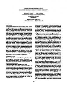
Constraints Control Control
Modification
Synthesis
Building Blocks Selection
Concretization Prototype
View Abstraction
Compilation
Application Program Fig. 1. Application Development Process in MetaFrame
End Users: They may modify a given application program by adding requirements in terms of behavioural traces. These requirements are then ‘merged’ with the given program to obtain a new application program that behaves as required along the new defining traces, but still as the original program everywhere else. Section 3.6 sketches this method together with the required frame conditions. The collection of professional profiles needed is often dictated by the application domain. The above list can of course be refined much further. The resulting overall lifecycle for application development using MetaFrame is two-dimensional: both the application and the environment can be enriched during the development process. Application Development. Its corresponding lifecycle is summarized in Figure 1. Based on libraries of BBs and constraints, an initial application program (the prototype) is graphically constructed under model checking control, and subsequently modified in an aspect-driven fashion: the application expert chooses an aspect of interest, generates the corresponding view abstracting from all irrelevant details, and modifies it where necessary. The effect of the modification can be automatically transferred to the underlying application program in a concretization step. This cycle is iterated until all relevant aspects have been treated. Due to the on-line verification with the model checker, constraint violations are immediately detected. Current prototypes can at any time be tested, compiled, executed, and, if satisfactory, stored in a repository. 4
Strengthening of the Environment. Application development is superposed by an orthogonal process of incremental strengthening of the application-specific environment: this happens by successively adding further BBs and consistency constraints. Both strengthenings proceed naturally, on demand: new BBs may turn out to become necessary when the range of the environment or the application are enlarged, or when it becomes obvious that certain code fragments have a high potential for reuse. The latter situation is supported by MetaFrame’s macro facility [23], which essentially allows one to encapsulate (fragments of) application programs as BBs. In the further development process, these blocks can be used just as ‘ordinary’ BBs. New constraints naturally arise when an erroneous BB combination pattern is detected in the test lab, or when new versions of BBs impose or induce compatibility constraints. MetaFrame explicitly separates BB implementations from their descriptions: for each application domain we have a distinct Meta-Data repository containing an abstract description of the BBs. The BBs themselves and their documentation are available in a different repository. As prototyping can start already as soon as the abstract description level of a domain is available, application experts can experiment with the combination of new BBs independently of their direct physical availability. This experimentation phase may in fact influence the choice and design of new BBs. In fact, MetaFrame explicitly encourages feedback flowing from the application experts to the programming experts by allowing abstract descriptions of BBs to be associated with simulation code, in order to prototypically use new BBs before they are actually implemented. Rather than providing a technical description of all these features and their impact, we will illustrate them along an industrial application: the design of intelligent network (IN) services. We gained experience in the area during an intense industrial cooperation in 1995/96, which led to a product that has been adopted, bought, and marketed by Siemens Nixdorf Informationssysteme AG (SNI) [20, 22, 23, 5, 21]. 1.2
Intelligent Network Services.
Intelligent Networks have changed the world of telecommunication in the last decade: by integrating telecommunication and computer technology, the Intelligent Network concept (see [9] for an overview) helps (network) providers to make new and flexible telecommunication services available to their customers. Concretely, complex programs steer the call handling of special telephone services, ranging from simple Free Phone services, where the called party pays the bill, to ambitious Virtual Private Network services establishing a distributed, private telephone network for a group of users within the public network. In fact, practically everybody has already made use of IN services. Particularly widespread examples are Televoting, Personal Mobility services, or Premium Rate Services, which enable the service subscriber to supply certain in5
SMP Service Administration
Data Communication Network
SCEP Service Customisation
Service Management Point Data Transmission
SCEP Customer Service Control
Data Communication Network (DCN) SCEP Service Definition
SCP
Service Control
Service Control Point
Signalling Transfer
CCS No. 7
SSP Service Access
IP Intelligent Peripheral
Service Switching Point Telephone network/ISDN
(A-Party)
(B-Party)
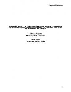
Fig. 2. Global Architecture of an Intelligent Network
formation (train schedules, stock quotes) under a unique number and against a usage fee. To satisfy the growing expectations on IN services, a flexible Service Definition Environment is a must. This need is independent of the current shift of emphasis from IN solutions towards unified messaging approches comprising also IP, GSM, satellite communication. The underlying Intelligent Network Architecture (see Fig. 2) is composed of several subsystems that cooperate to implement the intended functionality. They form complex distributed systems, where central computers, databases, the telephone network, and a huge number of peripherals must be coordinated under real-time, availability, and performance constraints. This complex structure makes modifications and extensions difficult and error prone. In particular, the design of new services must take into account requirements imposed by the underlying intelligent network: e.g., system-dependent frame conditions must be obeyed in order to guarantee reliable execution of the new services. Therefore, the introduction of complex services like the ones mentioned above typically still takes expert-years for development and testing. A good Service Definition Environment is intended to support a reliable service development, 6
tailored to the specifics of the intelligent network, in order to shorten time to market by reducing both the development and the testing phase. The challenge of the project with SNI in 1995 was to overcome the limitations of standard ’clipboard-architectures’ with some testing support: an environment for the creation of advanced Intelligent Network Services from a library of basic service components called SIBs (service independent building blocks) was required, which offers early error detection and correction features beyond the pure simulation-based approaches to service validation. The following section describes the essential steps of domain modelling required for the successful use of the MetaFrame environment in the light of the IN application. The impact of this modelling is illustrated in Section 3. Section 4 discusses the major design decisions for MetaFrame within the chosen application scenario. Finally, Section 5 presents our conclusions.
2
Domain Modelling
The central steps for domain modelling in MetaFrame are reflected by – – – –
Identification of SIBs Taxonomic classification of SIBs2 Constraint Modelling Structural and Behavioural Views
We will not enter the discussion here of how to identify an appropriate library of SIBs for a given application. This is part of a deep requirements analysis, which is typically dominated by the application experts in cooperation with the modelling expert.3 MetaFrame allows SIBs to be implemented in different application languages (C, ML, C++) of different programming paradigms (imperative, functional, object-oriented). This is important whenever legacy components need to be addressed. In this respect, this project dealt with a pure reorganization of the application development environment on top of legacy BBs: the underlying SIB library remained untouched. We now turn our attention to describing the use of taxonomies, models, constraints, and views in this application. 2.1
Taxonomies.
SIBs have an associated abstract description in terms of a taxonomic classification which establishes their (coarse) application profile within MetaFrame. Far from capturing their complete semantics (like e.g. algebraic specification approaches), taxonomic specifications are here intended to provide an abstract, application-specific characterization based on a collection of predicates. 2 3
In the full setting, we taxonomically classify BBs and types. ‘Historical’ growth of the SIB library, like in the IN-application, may severely hinder an efficient development of applications.
7
Fig. 3. Fragment of the SIB Taxonomy
Formally, taxonomies are labelled directed acyclic graphs. In this case, sinks represent concrete SIBs, the atomic entities of the taxonomy, and intermediate nodes represent groups, i.e., sets of SIBs with a particular profile. Edges reflect an is-a relation between their target and source node. Figure 3 shows a fragment of the SIB taxonomy as it is presented by the hypertext system. Here pin-change and check-pin are both sinks, and represent SIBs of the group authorization. The development of adequate taxonomies is a crucial part of the domain modelling as it provides users with an application-specific handle to the available BBs. Thus, in general, taxonomies must be extended not only when new functionalities are integrated, but also whenever one wants to establish a new ‘application-specific view’ on the so far integrated functionalities: the same BB may well be taxonomically classified completely differently in different application domains. E.g. establishing a network connection is quite central in the area of telecommunication, whereas it may be regarded just as a ‘commodity’ in another application area. In this project the taxonomies were defined freely, on top of an SNI-specific set of SIBs implementing the IN-functionality defined in the ITU standard. 8
2.2
Models and Constraints.
Services are modelled as flow graphs, whose nodes represent elementary SIBs, and whose edges represent branching conditions.4 Definition 1 (Service Model). A service model is defined as a quadruple (S, Act, →, s0 ) where – – – –
S is the set of available SIBs, Act is the set of possible branching conditions, → ⊆ S × Act × S is a set of transitions, s0 is the uniquely determined initial SIB.
In MetaFrame service models are subject to local and global constraints which, in conjunction, offer a means to identify critical patterns in the service graph already during the early design phase. The classification of constraints into local and global is important, as each kind requires a specific treatment. The on-line verification during the design of a new service, however, captures both kinds of constraints. Local Constraints. Local constraints specify single SIBs, their branching potential, as well as their admissible subsequent parameterization. Whereas branching potential and admissible parameterization require a special treatment, we will see in the next section that the loose specification of SIBs in terms of taxonomy expressions enters the global constraint language in form of atomic propositions. Definition 2 (Taxonomy Expressions). Let T AX be a taxonomy over some set. Then we can construct the corresponding set of taxonomy expressions by: te ::= A | ¬ te | te ∧ te | te ∨ te where nodes A ∈ T AX are taken as atomic propositions. Thus local SIB specifications are formulated as simple propositional logic formulas over the respective taxonomies, which are regarded as definitions of sets of basic predicates (atoms). The verification of local constraints is invoked during the global verification process. In the following we will omit details about the rather straightforward local verification and concentrate on the more interesting global constraints. 4
This modelling was preferred by SNI to the standard transition system-based modelling in MetaFrame, where BBs are represented by nodes and types by edges. The underlying model checking and synthesis components of MetaFrame easily adapt to this modelling.
9
Global Constraints: The Temporal Aspect. Global constraints allow users to specify causality, eventuality and other vital relationships between SIBs, which are necessary in order to guarantee executability and other frame conditions. A service property is global if it does not only involve the immediate neighbourhood of a SIB in the service model5 , but also relations between SIBs which may be arbitrarily distant and separated by arbitrarily heterogeneous submodels. The treatment of global properties is required in order to capture the essence of the expertise of designers about do’s and don’ts of service creation, e.g. which SIBs are incompatible, or which can or cannot occur before/after some other SIBs. Such properties are rarely straightforward, sometimes they are documented as exceptions in thick user manuals, but more often they are not documented at all, and have been discovered at a hard price as bugs of previously developed services. They are perfect examples of the kind of precious domain-specific knowledge that expert designers accumulate over the years, and which is therefore particularly worthwhile to include in the design environment for future automatic reuse. In the presented environment such properties are gathered in a Constraint Library, which can be easily updated and which is automatically accessed by the model checker during the verification. Besides the looseness in the specification of single BBs at the abstract level of the taxonomies, MetaFrame also supports the loose specification of whole call flows in terms of abstract constraints specifying precedences, eventuality, and conditional occurrence of single taxonomy objects. Typical pattern for this kind of loose specification are – general ordering properties, like this BB must be executed/reached some time before some other BB, – abstract liveness properties, like a certain BB is required to be executed/reached eventually, and – abstract safety properties, like two certain BBs must never occur within the same run of the system. In particular, users can specify elaborate requirements concerning the interplay between the occurrences of SIBs and conditions during the run of a specified INservice. In the following we present an according temporal logic, which comprises the taxonomic specifications of SIBs. Definition 3 (SLTL). The syntax of Semantic Linear-time Temporal Logic (SLTL) is given in BNF format by: 5
I.e., the set of all the predecessors/successors of a SIB along all paths in the model.
10
Φ ::= te | ¬Φ | (Φ ∧ Φ) | < c > Φ | G(Φ) | (ΦUΦ) where te represents a SIB constraint formulated as taxonomy expression, and c a possible condition. In the IN-application, SLTL formulas are interpreted over the set of all legal call flows, i.e. alternating sequences of SIBs and conditions6 which start and end with SIBs. The semantics of SLTL formulas is now intuitively defined as follows:7 – te is satisfied by every call flow whose first element (a SIB) satisfies the taxonomy expression te . – Negation ¬ and conjunction ∧ are interpreted in the usual fashion. – Next-time operator < > : < c > Φ is satisfied by all call flows whose second element (the first condition) satisfies c and whose continuation8 satisfies Φ. In particular, < tt > Φ is satisfied by every call flow whose continuation satisfies Φ. – Generally operator G: G(Φ) requires that Φ is satisfied for every suffix9 . – Until operator U: (ΦUΨ ) expresses that the property Φ holds at all BBs of the sequence, until a position is reached where the corresponding continuation satisfies the property Ψ . Note that ΦUΨ guarantees that the property Ψ holds eventually (strong until). The definitions of continuation and suffix may seem complicated at first. However, thinking in terms of paths within a flow graph clarifies the situation: a subpath always starts with a node (SIB) again. The interpretation of the logic over service models is defined path-wise: a service model satisfies a SLTL formula if all its paths do. The introduction of derived operators supports a modular and intuitive formulation of complex properties. Convenient are the dual operators False : Disjunction : Box : Eventually :
ff Φ∨Ψ [c]Φ F(Φ)
=df =df =df =df
¬tt ¬ (¬Φ ∧ ¬Ψ ) ¬ < c > (¬Φ) ¬G(¬Φ) =
(tt U Φ)
The following two simple examples illustrate typical loose sequencing constraints which can be conveniently specified in SLTL: 6 7 8 9
The absence of a condition is identified with the condition true. A formal definition of the semantics can be found in [19]. This continuation is simply the call flow starting from the second SIB. A suffix of a call flow is any subsequence arising from deleting the first 2n elements (n any natural number).
11
– F (connect) which means ‘A connect SIB is guaranteed to be reached eventually’. – G ( connect ⇒ F(charging) ) which is a liveness property meaning ‘Whenever a connect SIB occurs, then a charging SIB is guaranteed to eventually occur as well’. First-Order Extension. Our temporal logic also allows for first-order quantification over finite parameter domains [12]. Quantified formulas are expanded as needed for the considered service so that they can be checked by our iterative model checker. This may lead to an explosion of the number of constraints to be checked, but in our experience this did not turn out to be a serious bottleneck. Section 3.5 illustrates the use of these constraints in our Service Definition environment. 2.3
Views
The definition of aspect-specific views is part of the domain modelling phase, which is itself an incremental process. Structural Views allow capturing a system (here, a service) at a certain level of granularity, where subsystems are encapsulated as single SIBs. Behavioural Views are based on the idea of hiding aspects, like a specific kind of SIBs or conditions. These views can be defined explicitly by defining equivalences, i.e., visibility relations, on the set of SIBs and conditions, together with some structural properties, like the preservation of branching structure10 , or implicitly by means of temporal formulas. Structural Views: Macros. Technically, hierarchy is realized in form of a powerful mechanism for the definition, parametrization and reuse of macros, which is fully compatible with both formal verification and behavioural views. The macro facility covers the standard stepwise refinement approaches. This allows developers to define whole subservices as primitive entities, which can be used just like SIBs. As macros may be defined on-line and expanded whenever their interna become relevant, this supports a truly incremental service construction. Moreover, as macros have formally the same interfaces as SIBs, this enhances the reuse of already designed (sub-) services. Behavioural Views. Behavioural views are abstract service models. As such, they show aspects of actual, concrete models. They are used to hide any aspect of an IN model which is irrelevant wrt. an intended operation. This is useful during the development phase in order to concentrate on specific themes, e.g., the billing or the userinteraction contained in a service, while abstracting from all the rest. This complements the macro facility (for structural views) in order to attack the problem 10
In our case this is defined in terms of bisimulation[15].
12
of growing size of services, which may contain several hundreds of nodes and which are in their whole unmanageable. Most useful are error views, which are implicitly defined by global constraints. They reduce the service size on the basis of the so-called model collapse [24]. Their pragmatics is illustrated in the next section. In their handling, views do not differ much from the actual IN models. E.g. they can be loaded and edited in the usual way, however, often with quite dramatic effects: minor modifications on views may correspond to radical structural changes of the underlying concrete model. In addition, views can be created, corresponding to the application of an abstraction function, and applied to the underlying concrete model, corresponding to the application of a concretization function (cf. Fig. 1 and 5). Execution of a view means execution of the underlying concrete model. Fig. 4 shows a version of the UPT service, which has 158 nodes and 239 edges together with a comprehensible error view: just 10 nodes and 16 edges. Spotting the errors (informally explained in the pop-up window) in the original service graph is difficult, even though their location is indicated here by the thick arrows.
3
Using the MetaFrame-based Service Definition
The service definition environment must be easily usable also for pure application experts: IN-service designers with hardly any programming skills. They graphically build services on top of the SIBs, usually interactively, in cooperation or even in presence of the customers, and need an intuitive tool support which does not restrict creativity. 3.1
Background
Service Definition (SD) Environments for the creation of IN-services are usually based on classical ‘Clipboard-Architecture’ environments, where services are graphically constructed, compiled, and successively tested. Two extreme approaches to error handling characterize the state of the art of marketed SD environments: – The avoidance approach guarantees consistency by construction, but the design process is strongly limited in its flexibility to compose SIBs to new services. A representative of this category is e.g. described in [4], where the output of a Service Logic element is checked for its consumability by its successor. – The creative approach allows flexible compositions of services, but provides little or no feedback on the correctness of the service under creation during the development: the validation is almost entirely located after the design is completed. Thus the resulting test phase is lengthy and costly. [27] describes an IN environment to develop, in several cycles, service logic program 13
Fig. 4. The UPT Service with Two Violations, and an Error View with Error Location
14
Consistency Rules all constraints
Model Checker Modification
violated constraint
Verification
Concretization View
Service Logic Abstraction
violating Service Logic segment Path Constructor Fig. 5. The Service Design Process in IN-MetaFrame
instances from SIBs. After the services have been developed in the simulation environment, with a rich execution environment, additional tests of the new services are required in the live environment replacing simulated components. Our environment conjoins the desirable features of both approaches: the constraint-based Service Logic design restricts the liberal approach only where needed, while it provides a handle for formal methods-based early error detection and correction techniques. In combination with the traditional features and the sophisticated error correction support, this drastically reduces the ‘time to market’. 3.2
The Service Design Process
Figure 5, an application-specific refinement of Figure 1, summarizes the global structure of our approach, which supports an arbitrary decomposition of the design process. This is necessary, since the same Service Design environment is shared by teams of users with completely different profiles. We offer the needed design flexibility by means of the second of the following three phases: 15
1. A first draft of the service is usually obtained via modification of a preexisting service of similar application profile from the service library. A completely new design from scratch is also possible. Both design styles are supported by the macro facility and happen under model checking control. 2. The central design step consists of repeated, aspect-driven modification, implementing a point-of-view design strategy: the user chooses an aspect of interest, generates a corresponding view of the current service which abstracts from all details irrelevant for this point of view, and modifies it where necessary. Due to the on-line verification with the model checker, which is separately applicable also on views, constraint violations can be detected immediately. In this phase automatic expansion of macros may be required, in order to resolve ‘internal errors’. The effect of view modifications can be automatically transferred to the underlying model. This ‘apply’ operation is automatically supervised by the model checker: modifications disrupting the service structure are rejected. 3. Current service prototypes can at any time be tested, compiled, executed, and, if satisfactory, stored in the service repository. In combination with our concept of macros, views provide an extremely flexible service development. In addition, views support the realization of a very flexible access control mechanism, by enabling designers and service providers to define customer specific views with restricted modification potential. Views provide in fact a natural means to organize the central design process (step 2) into successive levels of refinement taking adequate care of role-specific areas of competences. In particular this allows us to tailor the environment for the specific needs of the service designer, the service provider, the customizer, and the user. The view-specific hiding can be used to automatically define and enforce access permissions. 3.3
Model Checking-Based Formal Verification
The service creation process is constantly accompanied by on-line verification of the global correctness and consistency of the service logic (Fig. 5). Vital properties concerning the interplay between (arbitrarily distant) SIBs of a service and the executability conditions for intermediate prototypes can be verified at any time during the design phase in a push-button fashion,via model checking. Design decisions that conflict with the constraints and consistency conditions of the intended service are thus immediately detected. Global properties concerning the interplay between the SIBs of a service are expressed in a user-friendly specification language based on SLTL, and gathered in a constraint library that is automatically accessed by the model checker during the verification. The maintenance of the constraint library is supported by a hypertext system. Our model checker is optimized for dealing with hundreds of constraints and moderate size systems (around 10.000 nodes), in order to allow their verification in real time. 16
Granny’s Free-Phone Service
Fig. 6. Granny’s Free-Phone Service with Forbidden Billing Error Location View
If the model checker detects an inconsistency, a plain text explanation of the violated constraint appears in a window as shown in Figure 6, and an error view is automatically generated, concentrating on the SIBs containing information relevant for the error detection, thus simplifying the location of the error. Corrections can be done directly on the error view, and the subsequent view application automatically updates the underlying concrete model. 3.4
Example: Granny’s Free-Phone
The service shown in Fig. 6 presents the flow graph of a simple kind of FreePhone (800-service). In essence, the service logic is the following: after a call initialization section common to all services, the caller dials the desired specific Free-Phone number, then a prompt requires entering a Personal Identification 17
Number (PIN) and, depending on the time of the day, the call is either released (in the forbidden time windows) after an announcement, or it is routed to the desired destination number. A ‘Billing Constraint’. The following Billing Constraint Unsuccessful calling sections will not be charged guaranteeing a property Germans are used to, can be expressed by the formula release ⇒ ( ¬zone BU ( prompt ∨ initdp ) ) Here BU stands for a backward until modality, which is not part of SLTL, but can nevertheless be dealt with by our model checker. Intuitively, it is interpreted as the standard until operator on a service model, where all edges have been reverted. Intuitively the formula expresses the Billing Constraint as follows: traversing the service model backward from the release SIB, which marks unsuccessful call attempts, no zone (i.e. call segment charging) SIB should be met on the segment, which is delimited by a prompt or by an initdp SIB. The verbal formulation is shown in Fig. 6(middle). Here we see that the logic allows expressing constraints not only along the flow of the call (forward constraints), but also in the opposite direction. Thus, a wide class of causality interactions can be elegantly and concisely formulated, successfully checked, and efficiently enforced. In our example, model checking the Free-Phone service wrt. this constraint results in the discovery of erroneous paths in the graph. To ease its location and the correction of the error, an abstract error view is automatically generated, to evidence only the (usually few) relevant nodes. In order to supply a maximum of information concerning the error, error views do not touch the erroneous part, but constrain the application of the (model) collapse to the correct portion of the service. This choice also supports error correction, since the attention is immediately drawn on the (usually small) erroneous portion of the service logic, which is presented to a level of detail typically sufficient for correcting the error. Fig. 6(right) shows the automatically generated error view with error location information for that same service and constraint. – The error locating view has been obtained automatically after the failed model checking. Irrelevant nodes are collapsed in the unlabelled nodes. It is now easy to see that there is a constraint violation along the (unsuccessful) path between the release and the initdp SIBs: the portion evidenced by the highlighted arrows contains a zone SIB which is not allowed on this path. The location of the error is thus much more easily spotted than by inspection of the whole graph. – The view graph can be directly edited, e.g. by deleting the zone SIB. – The view application actualizes the corresponding IN-service model which is thus automatically corrected. A new verification via model checking confirms the conformance of the resulting service. 18
Note the precision and conciseness of the diagnostic information: the checked properties involve an interplay of several SIBs along a path, which usually describe their relative positioning in a loose fashion. Thus they leave room for several alternatives. As a consequence, legal error correction is not unique (in the example, one could insert a new call segment delimiter (prompt) at any place on the path below the zone SIBs), and a corresponding automatic selection process is not wished, as it would unnecessarily constrain the designer, who usually chooses the appropriate correction according to other (semantic) criteria. In this case, service providers may desire billings to be valid on the longest possible portion of a call segment. Thus the most convenient location for the zone SIB is immediately before the last prompt SIB on the path. Of course this simple example service could have been still easily handled by hand, but current IN services have reached sizes and complexities which demand for automated support for error detection, diagnosis, and correction. Our environment encourages the use of the new method, as it can be introduced incrementally: if no formal constraints are defined, the system behaves like standard systems for service creation. However, the more constraints are added, the more reliable are the created services [21]. 3.5
Typical Constraints
This section summarizes some typical constraints, which provide a good feeling for the style and common patterns in temporal constraint specification. They comprise backward modalities and examples for constraints written in our firstorder extension of SLTL: – ‘All call sections (which are separated by prompt or initdp SIBs) are separatedly billed’. Billed segments are determined by an initializing billing SIB and a corresponding closing call-line-charging SIB. ( prompt ∨ initdp ) ⇒ ( ¬call-line-charging U billing ) – ‘Every pin-protected path in a service only leads to a successful connection if the final pin check was successful’. The slightly indirect modelling of this property assumes that the check pin SIB only has two outgoing branches, marked False and True. check pin ⇒ [ False ] ( ¬destination U check pin ) – More technical is the following constraint: write user destination ⇒ ( ¬prompt BU read dialled number ) which means that ‘every write user destination SIB must be preceded by a read dialled number SIB before a prompt SIB occurs’. This is exactly the constraint underlying the error view in Figure 4. 19
The following constraints make use of our first-order extension of SLTL. This extension was not part of the product delivered to SNI in 1995. – ‘counter SIBs are only allowed to appear after a corresponding init SIB’, making sure that counting is always properly initialized. The parameter is only used to identify different counters within the same service. ∀n. counter(n) ⇒ BF ( init(n) ) – More complicated is the following constraint guaranteeing pathwise version compatibility: ‘on every path, where SIB1 occurs in version n, each subsequent occurrence of SIB2 is at least of version n + 2’. ∀n. Version(SIB1) = n ⇒ G ( Version(SIB2) ≥ n + 2 ) – Finally, it is also possible to express global version consistency properties, like: ‘whenever a SIB occurs in version n within a service, then all its occurrences are of version n’. ∀n. ¬G (¬Version(SIB) = n ) ⇒ G (Version(SIB) = n ) In fact, in discussions with application experts it turned out that only very few simple patterns of constraints are required in order to express most of the desired properties. Thus application experts should be able to input their own constraints on the basis of very few corresponding templates. 3.6
Safe Service Customization
The incremental formalization approach, where (global) constraints are added online, aims at establishing a (loose) correctness filter but is far from guaranteeing correctness. Thus that responsibility remains with the programming or application expert. This approach is not applicable for customizers, subscribers or end users: they require a dual assistance, which constrains their freedom of design in order to guarantee consistency and executability. Safe Service Customization [6] is such a technique. It flexibly supports subscribers in their desire of modifying the service logic in a controlled fashion, while guaranteeing that the modified services can immediately be activated, without previous intervention of specialists like service designers or testers. Thus it goes far beyond the usual service adaptation capabilities, which either – concern user-specific data only, like changing the PIN or modifying the time windows or the destination numbers for some routings, or – are restricted to the combination of a small selection of Features or Service Independent Building Blocks, like e.g. those for call center functionality. Together with its call flow-oriented user interface, our technique satisfies the following two requirements, essential for success in a competitive market: 20
Merge Input: User dialogue Dialled Number Announcement PIN Announcement Destination Number
Verify
Constraints
Modified Service Logic
SIBs Services
Fig. 7. The Service Modification Process
1. Ensured safety of the IN system: service modifications and definitions can only be accepted if they do not affect the reliability of the currently running system. 2. Comfortable and intuitive user’s guidance: wide distribution also among nonexperts requires a self-explaining tool. As sketched in Fig. 7, our system offers service subscribers the possibility of modifying the service logic simply by giving call flow skeletons describing the desired user dialogues (left): by their nature, these do not require any advanced technical knowledge. The dialogues can then be integrated into a pre-existing (or basic) service (e.g. the off-the-shelf UPT just subscribed) by means of an advanced synthesis technique, which takes care of the vital consistency and frame conditions guaranteeing reliability. The result is a minimal running extension of the basic service that also provides all the features specified by the given call flows. An on-line testing facility allows users to validate whether all their desires are now satisfied. This safe service customization technique has been developed only after the delivery of our service definition environment to SNI.
4
Some Reflections
How practical and widely applicable is the MetaFrame environment? The following reflections are dictated by considerations of ‘soft’ criteria, like acceptability, usability and extensibility. 21
4.1
Separation of Concerns
This principle is a methodological cornerstone of our environment. It plays a central role in our service definition environment e.g. for the management of teams of designers that work on several aspects of the service under development. Examples for required separation of concerns are the ‘classical’ distinction between environment administrators, service designers, and service customizers with their role-based responsibilities, as well as thematic-oriented separations according to the aspect currently considered, e.g. user interaction, billing, exception handling, routing and network related features. Our tool supports separation of concerns – at the description level, by offering a variety of constraint languages on different abstraction levels [19], which are typically tailored for different user groups, and – at the presentation and operation levels, e.g. by means of its flexible view mechanism, which highlights the essence of the considered design decision by hiding all the irrelevant details of the overall service graph [20]. 4.2
Parameterization, Exchangeability and Reuse
Due to the abstract view of the components as coarse-grain, highly parameterized procedural entities, their use is largely independent of their concrete realization. Interchangeability of the implementing code has been exploited e.g. in order to offer mixed-mode simulation of services. A component may in fact have several implementations: – at differents abstraction levels, from functional prototypes (adequate for service animation) to the code running on the installed Service Control Point. – for operability in different environments (e.g., vendor-, country-, standarddependent). Mixed-mode simulation enables the execution of services whose components are not homogeneously realized. Obviously, correct executions are only possible if the interoperability is guaranteed. Temporal constraints provide a corresponding abstract means. Besides the direct reuse of components in a different setting, we support a more flexible reuse policy in the prototyping phase: a flexible wrapper/adapter concept makes BBs11 uniformly accessible for graphical, behaviour-oriented application programming, and application-specific taxonomies, which may categorize one and the same BB completely differently in different contexts, provide an application-specific view onto the content of the BB libraries. This supports the construction of complex heterogeneous application programs by providing policies for a context-dependent reuse of existing modules beyond the native application domain, as long as the patterns of usage are compatible. 11
In particular also functionalities of legacy software.
22
4.3
Tailoring of the Visible Complexity
The described view concept provides all user groups of the development environment with a tailored representation of the system under construction. These representations, which arise as abstracted versions of the overall system representation in terms of a flow graph-like structure, are formally derived on the basis of hiding, abstract interpretation, model collapse and renaming concepts. The whole system development can be reduced to stepwise modifications of adequate role- or topic-specific views, like the error view shown in Fig. 4. 4.4
Semantics-Based Control
Systems, as well as their underlying domain model, can be loosely specified in terms of modal-logic constraints [3]. MetaFrame provides a model checker for the corresponding verification, and a synthesis tool for guiding the development process [25]. Design errors like those spotted in Fig. 4 are in fact automatically detected on-line within seconds, even for libraries of hundreds of constraints. Important feature is here the full automation of these tools, which are indeed profitably used without requiring any specific knowledge of the underlying formal methods. 4.5
Incremental Formalization
The key to the acceptance of our system development method in the industrial context was its incremental formalization character [21, 6], ranging from ‘no extra specification’, resulting in the old-fashioned development style, to ‘detailed specification’, exploiting full tool support. In fact this property was probably psychologically most important for the acceptance of the tool within the SNI designers group and by their customers, because it builds upon familiar development habits. 4.6
‘Evolutionary’ Application Programming
The idea to this development style, which provides non experts with restricted programming power, first came up in connection with the ETI platform [19, 7], but turned out to be nicely applicable to the IN scenario (cf. Section 3.6). The proposed combination of inputs in terms of user dialogues, controlled extension by means of our synthesis feature, and validation in terms of animation guarantees reliability while allowing service subscribers a flexible and intuitive means to customize their services, including modifications of the Service Logic. This flexibilization and simplification of the service customization process reduces the costs for tailored intelligent network services and therefore provides a key to a service-on-demand market. Currently, we are exploring these concepts as a powerful means for personalizing internet services. 23
All these methods aim at making a global behaviour-oriented approach to programming applicable, essentially by reducing the apparent size of the underlying global model. The success of this approach therefore strongly depends on the existence of an adequate granularity and on the adequacy of the temporal constraint-based specification mechanism. We have a very promising experience with ‘workflow-oriented’ systems, which provide a flexible management and organization of collections of components, like in the IN application. On the other hand, the design of the underlying libraries of components themselves or the construction of large concurrent systems should be done by other means. E.g., we use the object-oriented approach for the design of our component libraries.
5
Conclusions
The presented approach exactly meets the demands for the emerging paradigm of Domain Specific Formal Methods [10]: use formal methods on a large or huge grain level rather than on elementary statements, thus support the programming with whole subroutines and modules as elementary building blocks. This is precisely what MetaFrame is designed for and what the application to IN services embodies. Still, the step towards the use of formal methods is rather big and can hardly be done at once. The MetaFrame environment therefore offers a lazy and incremental use of formal methods: if no formal constraints are defined, the system behaves like standard systems for service creation. However, the more constraints are added, the better is the automatic control and the more reliable are the created services. In fact, in the extreme case of a full specification of the vital frame conditions, very few representative tests are required to guarantee the correctness of the service. Experience shows that it is often impossible to write complete formal specifications in practice. E.g. in the case of service creation, the knowledge about the exact requirements is distributed over several groups along the development process, and it is only used implicitely during the development. Thus people need to learn that and how this knowledge should be made explicit. The incremental refinement of the formal specification, by successively adding more and more constraints, provides a ‘soft’ entry into the world of formal methods.
Acknowledgement The technical development of the MetaFrame environment, as well as of its instance for the IN application, was competently promoted and supervised by Volker Braun. He took over leadership of the MetaFrame team from Andreas Claßen early in 1995, and made sure that the environment reaches industrial strength. We are very grateful to the whole MetaFrame team, in particular to Achim Dannecker and Andreas Holzmann, who accompanied the development from the very beginning. 24
Finally, we would like to thank Gerhard Goos, Bengt Jonsson, Markus M¨ ullerOlm and Perdita Stevens for their constructive feedback.
References 1. Digilog, Inc.: Atelier-b online. http://www.atelierb.societe.com/index_uk.html 2. B-Core(UK) Ltd., B-tool documentation. http://www.b-core.com/ 3. M. von der Beeck, B. Steffen, T. Margaria: “A Formal Requirements Engineering Method and an Environment for Specification, Synthesis, and Verification”, Proc. of SEE ’97, 8th IEEE Conference on Software Engineering Environments, Cottbus (Germany) 8-9 April 1997. 4. P. K. Bohacek, J. N. White: “Service Creation: The Real Key to Intelligent Network Revenue”, Proc. Workshop Intelligent Networks ’94, Heidelberg, May 24-26, 1994. 5. V. Braun, T. Margaria, B. Steffen, H. Yoo: Automatic Error Location for IN Service Definition, Proc. AIN’97, 2nd Int. Workshop on Advanced Intelligent Networks, Cesena, 4.-5. Juli 1997, in “Services and Visualization: Towards User-Friendly Design’, LNCS 1385, Springer Verlag, M¨ arz 1998, pp.222-237. 6. V. Braun, T. Margaria, B. Steffen, H. Yoo, T. Rychly: Safe Service Customization, Proc. IN’97, IEEE Communication Soc. Workshop on Intelligent Network, Colorado Springs, CO (USA), 4-7 May 1997, IEEE Comm. Soc. Press. 7. V. Braun, T. Margaria, C. Weise: Integrating Tools in the ETI Platform, [25], pp.31-48. 8. Design/CPN Online. http://www.daimi.au.dk/designCPN/ 9. J. Garrahan, P. Russo, K. Kitami, R. Kung: “Intelligent Network Overview,” IEEE Communications Magazine, March 1993, pp. 30-37. 10. J.A. Goguen, Luqi: “Formal Methods and Social Context in Software Development,” (invited talk) 6th Int. Conf. on Theory and Practice of Software Development (TAPSOFT’95), Aarhus (Denmark), May 1995, LNCS N.915, pp.62-81. 11. D. Harel, M. Politi: Modeling Reactive Systems With Statecharts : The Statemate Approach, McGraw Hill, October 1998, ISBN: 0070262055 12. J. Hofmann: Program Dependent Abstract Interpretation, Diplomarbeit, Fakult¨ at f¨ ur Mathematik und Informatik, Universit¨ at Passau, August 1997. 13. L. Kristensen, S. Christensen, K. Jensen: The Practitioner’s Guide to coloured Petri Nets, STTT, Int. Journal on Software Tools for Technology Transfer, Vol.2, N.2, pp.98-132, December 1998, Springer Verlag, DOI 10.1007/s100099800003. 14. P. Leblanc: OMT and SDL based techniques and tools for design, simulation and test production of distributed systems STTT, Int. Journal on Software Tools for Technology Transfer, Volume 1 Issue 1+2 (1997) pp. 153-165, December 1997, Springer Verlag. 15. R. Milner: Communication and Concurrency, Prentice-Hall, 1989. 16. Oracle, Inc. Oracle Designer information page. http://www.oracle.com/tools/designer. 17. The Raise Project homepage. http://dream.dai.ed.ac.uk/raise/ 18. Rational, Inc. The Rational Suite description. http://www.rational.com/products. 19. B. Steffen, T. Margaria, V. Braun: The Electronic Tool Integration platform: concepts and design, [25], pp. 9-30.
25
20. B. Steffen, T. Margaria, A. Claßen, V. Braun, M. Reitenspieß: “An Environment for the Creation of Intelligent Network Services”, invited contribution to the book “Intelligent Networks: IN/AIN Technologies, Operations, Services, and Applications – A Comprehensive Report” Int. Engineering Consortium, Chicago IL, 1996, pp. 287-300 – also invited to the Annual Review of Communications, IEC, 1996, pp. 919-935. 21. B. Steffen, T. Margaria, A. Claßen, V. Braun: Incremental Formalization: a Key to Industrial Success, in “Software: Concepts and Tools”, Vol.17(2), pp. 78-91, Springer Verlag, July 1996. Tool presentation in AMAST’96, Munich, Juli 1996, LNCS, Springer Verlag. 22. B. Steffen, T. Margaria, A. Claßen, V. Braun, M. Reitenspieß, H. Wendler: Service Creation: Formal Verification and Abstract Views, Proc. 4th Int. Conf. on Intelligent Networks (ICIN’96), Nov. 1996, Bordeaux (France), pp. 96-101. 23. B. Steffen, T. Margaria, V. Braun, N. Kalt: Hierarchical Service Definition, Annual Review of Communic., Int. Engineering Consortium, Chicago, 1997, pp.847-856. 24. C. Stirling: Modal and Temporal Logics, In Handbook of Logics in Computer Science, Vol. 2, pp. 478 – 551, Oxford Univ. Press, 1995. 25. Special section on the Electronic Tool Integration Platform, Int. Journal on Software Tools for Technology Transfer, Vol. 1, Springer Verlag, November 1997 26. Telelogic AB. Tau’s description. http://www.telelogic.com/solution/tau.asp 27. Mike Wrax, Mark Syrett: “Service Creation Using the Hewlett-Packard Service Creation Environment”, Proc. Workshop Intelligent Networks’94, Heidelberg, May 24-26, 1994.
26