alloys offer a combination of good corrosion resistance, resistance to stress corrosion cracking in various service ...
Would you like to receive a hardcopy of this magazine's full publication? Please include the month and year of publication and contact Mrs. Erica Riethorst at
[email protected]
DUPLEX
Duplex Stainless Steel:
Metallurgy, engineering codes & welding practices (Part 2 of 2) Duplex stainless steels are synonymous with extremely demanding service applications. These alloys offer a combination of good corrosion resistance, resistance to stress corrosion cracking in various service media, with good mechanical properties. These steels are frequently used in the oil and gas industries (and chemicals/petrochemical industries) both in upstream and downstream applications for components, e.g. pressure vessels, exchangers, pipe work systems, manifolds and risers, valve and other applications. Although duplex stainless steels in many cases are superior in corrosion resistance and strength compared to 304 and 316 austenitic stainless steels, many fabricators continue to have difficulties creating welding procedures that yield repeatable weldments with optimum properties. This paper offers an overview of the issues involved in achieving high integrity, high quality, duplex stainless steel weldments.
By Pradip Goswami, P. Eng., IWE, Welding and Metallurgical Specialist - Ontario, Canada & Ramesh Bapat, Senior Principal Engineer, Foster Wheeler Upstream www.stainless-steel-world.net
S t a i n l e s s
S t e e l
W o r l d
J a n u a r y / F e b r u a r y
2 0 1 4
1
DUPLEX Introduction
Originally intended for offshore oil and gas applications, duplex/super duplex stainless steels are the preferred material for engineering applications in many downstream industries e.g. petroleum, refining, chemical and petrochemical etc. A combined characteristic of both ferritic and austenitic stainless steels imparts the required design properties in these steels when welded properly. Table 1 lists some of the mechanical properties of these steels as per various ASME BPV codes. Design wall thickness reduces significantly when duplex grades are used for design. This reduction is primarily due higher Yield strength of DSS/ SDSS as compared to austenitic alloys. Also the citations from NACE –MR-0175/ ISO-15156-3 on operating service are indicated in Table 2. The metallurgy of the duplex stainless steel family is complex and requires very close control of weld metal composition and heat treatment regimes to ensure that mechanical properties and/ or corrosion resistance would not be adversely affected. To produce the optimum mechanical properties and corrosion resistance, the microstructure or phase balance of both
the parent and weld metal should be approximately 50% ferrite and 50% austenite. This precise value is impossible to achieve with accuracy, but a range of phase balances between 35 - 60% ferrite and the rest austenite is acceptable in the various industry standards.
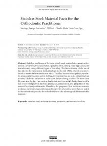
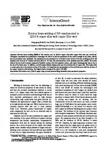
Recommended welding processes must be ideally suitable for, (a) positional welding, (b) productivity, (c) technical compliances to design codes/design specifications and others as desired. SMAW is excellent for positional welding, weld joints where access is limited. Direct Current (DC+) gives the best welding results and most electrodes are manufactured to suit this. A short arc is always recommended for SMAW which gives the best stability and reduces the risk of nitrogen pickup. Nitrogen is very important for balanced ferrite / austenite ratio in the welds. Gas Metal Arc Welding (GMAW) is a popular process. If used, “pulsed current” (GMAW-P) should be specified as the best option, both for duplex and super duplex grades. GTAW is universally used for welding of this alloy. It is strongly recommended as a welding process with very high integrity. It is specifically common for pipe joints (single sided Full Penetration Welds). FCAW is especially advantageous for weld thicknesses above (1/2”) or, 12.7mm. Positional welding is very good. Gas shielding (100% Argon or 80% Argon + 20% CO2) is always to be used as the shielding & backing gas.
Figure 1: Welding Duplex Pipe work, Single Sided Process, Recommended Welding Process(4).
Welding of Duplex and Super Duplex Stainless Steels
Welding duplex and super duplex stainless steels to design code / specification requirements are always challenging. Duplex/Super Duplex Stainless Steels are weldable by all conventional arc welding processes e.g. SMAW, GMAW, GTAW, SAW and FCAW. Autogenously welding must follow subsequent heat treatment (solution anneal), to balance austenite to ferrite ratio. Absence of heat treatment (in Autogenous Welds) could risk higher ferrite in the weld, resulting poor ductility and poor corrosion resistance.
Table 1: Mechanical properties of various duplex and 316L S.S(1). UNS No
Grade
Tensile Strength Yield Strength, min (MPa) (MPa)
Elongation %
Hardness, max, Brinell
Recommended Maximum Design Temperatures, ASME, ºC/ºF
S32304
2304
600
400
25
290
315/600
S32101
2101
650
450
30
290
315/600
S31803
—
620
450
25
293
315/600
S32205
2205
655
450
25
293
315/600
S32550
255
760
550
15
302
315/600
S32750
2507
795
550
15
310
315/600
S32760
Z100
750
550
25
270
315/600
S31603
316L
485
170
40.0
217
475/900
Table 2: Environmental & materials limits for duplex stainless steels. Offshore applications: NACE MR-0175, IS0 15156-3. Materials Type / UNS Number
Temperature Max, °C (°F)
Partial Pressure H2S, pH2S, Max., kPa (psi)
Chloride Conc, Max. mg/l
pH
Sulfur- resistant (Y/N)
30≤ FPREN ≤40, Mo≥ 1.5%
232(450)
10(1.5)
See remarks
See remarks
S31803(HIP)
232(450)
10(1.5)
See remarks
See remarks No
40< FPREN < 45
232(450)
20(3)
See remarks
See remarks
2
S t a i n l e s s
S t e e l
W o r l d
J a n u a r y / F e b r u a r y
2 0 1 4
No data submitted
No data submitted
Remarks Any combinations of chloride concentration and in situ pH occurring in production environments are acceptable.
www.stainless-steel-world.net
DUPLEX Table 3: Typical welding parameters for different types of joints(5). Technique
Electrode / Dia (in) Filler
Suitable Welding Recommended Position Current (A)
Voltage (V)
Travel Speed (ipm)
Approximate Oxygen Content-WM (ppm)
SMAW
E-2209
3/32 & 1/8
All
50-60 80-95
20-24
4-6/7-9
500-650 (Basic Coating) 1000-1500 (Rutile Coating)
GTAW
ER-2209
3/32
All
100-120
16-18
5-8
50-150
GMAW
ER-2209
0.45
All
170-230
28-30
17-22
150-450
FCAW
E2209T1-4 1/16
All
190-210
28-30
17-22
1100
SAW
ER-2209+ P100 Flux
1G
350-400
30-32
30-40
500-650
3/32
Table 4: Recommended shielding gases for GMAW, GTAW & FCAW. Welding Process
Shielding Gases Ar+30 He+1 O2
GMAW
Remarks Short arc welding gives very convex beads
Ar+30 He+1 O2 (22Cr duplex) Ar+2 CO2 (Super duplex)
Spray arc welding
Shielding - Ar+2% N2 Purging / Root Gas- Ar
Purge to maintain 0.5% oxygen max Ar + 2% N2 shielding gas is recommended for the root run. For subsequent runs, Argon (Ar) may be used as shielding gas. Purging/Root gas is mandatory for first two runs. Note: Per ASME Sec-IX, a change for purging gas is a non-essential variable. Formier gas (90% nitrogen and 10% hydrogen) is a cheaper and sometimes a tried alternative for root passes. Final acceptance is subject to satisfactory procedure qualification only.
Ar-20% CO2 Ar-18%CO2 -2%O2
Typical gas flow rate 20-25 l/min Wire sickout length 15-20mm
Ar+30 He+1 O2 (22Cr duplex) Pulsed arc welding Ar (99,996%) for super duplex
GTAW
FCAW
SAW is widely used when welding thicker sections (1” & above) is involved and when productivity and good weld finishes are of concern. The disadvantages of SAW are that it is restricted to the downhand (1G) position and that the heat input is relatively large. Hence typically the wire diameter is restricted to either 1/16” (1.6mm) or 3/32” (2.4mm) to minimize heat input. Basic agglomerated Special fluxes, e.g. Vista 805, Met rode SSB & LA491 are well proven for SAW of DSS/SDSS.
Welding Techniques
In single sided welds (very common for duplex alloy pipe work), the root pass needs a well controlled welding process/technique (typically GTAW) and filler metals capable of delivering good corrosion resistance. Filler passes can be welded by SMAW/GMAW-P or FCAW suited for maximum productivity, and the best mechanical properties (strength and toughness). Filler wire must always be added, root runs should not be made autogenously. www.stainless-steel-world.net
For root runs as much filler as practical within the heat input restrictions should be added. As a guideline the root run thickness should be ~2mm on thin wall tube (3-4mm) rising to 3 or 4mm as pipe thickness increases.
Purging
A gas purge must be used for root runs in GTAW process and will normally be maintained for the first three layers or approximately 10mm of deposit. Commercially pure argon is generally used as the purge gas. Purge flow rates are determined by the pipe size but it is important that following the removal of tacks, grinding etc that the purge is allowed to stabilise again before welding. The efficiency of the purge should be monitored with an oxygen monitor to ensure the oxygen content is maintained below 0.5% oxygen (see in Table 3 also).
Role of Shielding Gases
Conventional shielding gases used for welding austenitic stainless steels works S t a i n l e s s
S t e e l
equally well with DSS/SDSS. When acceptable by specifications, argon may be used with an addition of 2% O2. Addition of oxygen in the shielding gas increases wetting of the weld pool. For thicker sections (¾” upwards) addition of around 30% helium is advisable. Such helium addition increases arc energy, increases weld pool fluidity, enables higher welding speeds. GTAW is typically performed with pure argon as the shielding gas. Resistance to, pitting corrosion is considerably increased by the addition of up to 2% nitrogen. However, the risk of weld porosities and the rate of Tungsten electrode wear increases with increased nitrogen content above 2%. GMAW shielding gases are somewhat more complex than GTAW. The GMAW shielding gasses could range from 100% pure argon to about 80% argon+ Helium+ Nitrogen+ Oxygen in various proportions to enhance weldability and final properties. Some recommendations are specified in Table 4 (although it could be subject to test results. W o r l d
J a n u a r y / F e b r u a r y
2 0 1 4
3
DUPLEX
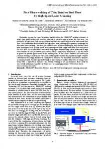
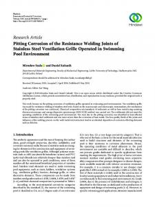
Figure 2: Micrographs of both duplex and Austenitic alloys(2).
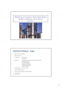
Figure 3: Schaeffer diagram: predicted ferrite content of various duplex weld metals(2).
Welding Variables
generally regarded as necessary for duplex stainless steels unless the ambient conditions mean that the steel is below 5°C or there is condensation
Preheating & Interpass Temperature Preheating is not necessary for duplex and super duplex grades. Preheat is not
on the surface. In these situations a preheat of around 50 - 75°C should be adequate. Higher Interpass temperatures have a significant effect on the microstructure of the weld & HAZ’s. For duplex steel & super duplex grades advisable maximum interpass temperature is generally 150°C. When welding the DSS, the heat input and the cooling rate are important parameters. At high temperatures the solubility of nitrogen in the ferrite is cooling causes a drop of solubility and formation of chromium nitrides. A limited amount of chromium nitrides does not have any effect on the properties of the weld unless they
Table 5: Chemical composition of commonly used DDS and other alloys(1). UNS #
Type
Cr, wt%
Mo, wt%
Ni, wt%
N
Cu
Min PREN d
Other
First Generation DSS S32900
Type 329
23.0 - 28.0
1.0 2.0
2.5 - 5.0
-
-
S31500
3RE60
18.0 - 19.0
2.5 - 3.0
4.25 - 5.25
0.05 - 0.10
26.3
-
27.1
Lean and Semi Lean DSS S32304
2304
21.5 - 24.5
0.05 - 0.60
3.0 - 5.5
0.05 - 0.20
0.05 - 0.60
22.5
-
S32101
2101
21.0 - 22.0
0.10 - 0.80
1.35 - 1.70
0.20 - 0.25
0.10 - 0.80
24.5
-
S32003
2003
19.5 - 22.5
1.50 - 2.00
3.0 - 4.0
0.14 - 0.20
-
26.7
-
25%Cr and Super Duplex S.S S32550
255
24.0 - 27.0
2.9 to 3.9
4.5 to 6.5
0.10 - 0.25
1.50 - 2.50
35.2
-
S32750
2507
24.0 - 26.0
3.0 to 5.0
6.0 to 8.0
0.24 - 0.32
0.50
37.7
-
S32760
-
24.0 - 26.0
3.0 to 4.0
6.0 to 8.0
0.20 - 0.30
0.50 - 1.00
37.9 d
W: 0.5 - 1.0
S32950
-
26.0 - 29.0
1.0 to 2.5
3.5 to 5.2
0.15 - 0.35
-
31.7
S39274
-
24.0 - 26.0
2.5 to 3.5
6.0 to 8.0
0.24 - 0.32
0.20 - 0.80
38.6
W: 1.5 -2.5
S39277
-
24.0 - 26.0
3.0 to 4.0
6.5 to 8.0
0.23 - 0.33
1.20 - 2.00
38.9
W: 0.8 - 1.2
Table 6: Welding consumables for various duplex stainless steels (refer to ASME BPV Code, Sec-II, Part C, 2010)(1) & (4). Welding UT.S AWS Process / min, % El Classification SFA No Ksi/MPa SMAW – SFA-5.4
GTAWGMAWSAWSFA-5.9
4
C
Cr
Ni
Mo
Mn
N
Cu
Other
E2209-XX
100/690 20
0.04 21.5 - 23.5 8.5 - 10.5 2.5 - 3.5 0.5 - 2.0
0.08 - 0.20 0.75
-
E2553-XX
110/760 15
0.06 24.0 - 27.0 6.5 - 8.5
2.9 - 3.9 0.5 - 1.5
0.10 - 0.25 1.5 - 2.5
-
E2593-XX
110/760 15
0.04 24.0 - 27.0 8.5 - 10.5 2.9 - 3.9 0.5 - 1.5
0.08 - 0.25 1.5 - 3.0
-
E2594-XX
110/760 15
0.04 24.0 - 27.0 8.0 - 10.5 3.5 - 4.5 0.5 - 2.0
0.20 - 0.30 0.75
E2595-XX
110/760 15
0.04 24.0 - 27.0 8.0 - 10.5 2.5 - 4.5 2.5
0.20 - 0.30 0.4 - 1.5
ER2209
100/690 20
0.03 21.5 - 23.5 7.5 - 9.5
2.5 - 3.5 0.50 - 2.00 0.08 - 0.20 0.75
ER2553
110/760 15
0.04 24.0 - 27.0 4.5 - 6.5
2.9 - 3.9 1.5
ER2594
110/760 15
0.03 24.0 - 27.0 8.0 - 10.5 2.5 - 4.5 2.5
S t a i n l e s s
S t e e l
W o r l d
J a n u a r y / F e b r u a r y
2 0 1 4
W = 0.4 - 1.0 -
0.10 - 0.25 1.5 - 2.5 0.20 - 0.30 1.5
W= 1.0
www.stainless-steel-world.net
DUPLEX Table 7: Welding procedure qualification for DSS/SDSS, ASME Section IX and other specifications’ requirements’(1) & (5). Test
Purpose
Remarks
Tensile Test
Weld must equal or exceed the As stated previously base metal tensile strength.
Impact Testing
Toughness measurement
Typically associated with minimum design temperature and engineering recommendations Frequent requirements, for parent and weld metal are minimum 45J average at -46°C per ASTM A923 Method B. Note:- this requirement may differ also as mandated by design/project specifications.
Hardness survey
Check maximum allowable hardness
Depends on DSS grade and service environment Recommended, 28 HRC for DSS grades, 32 HRC for SDSS grades
Ferrite Measurements Determines % ferrite Point Count Method
Check ferrite/austenite balance for entire weldment thickness. Optimal ferrite content between 35-60%. ASTM-E 562 is commonly followed.
Pitting Corrosion Test ASTM- G48A
Evaluates resistance of DSS/SDSS to pitting and crevice corrosion in chloride environments. Typical test temperature 30-50°C for DSS & SDSS. This may vary subject to design requirements. Very severe test, acceptance criteria No Pits in the Weld/HAZ/BM or a maximum weight loss of 4g/mm2.
are located to the grains close to the surface. In that case, the corrosion resistance will be decreased because of the depletion of chromium. Thus, welding of heavy wall thicknesses with too low heat input must be avoided. Recommended heat input is typically between 0.5-2.5 KJ/mm for DSS and 0.5-1.5 Kj/mm for SDSS.
Erratum
In the December issue of Stainless Steel World, in part 1 of this article, page 63, column 2, it was stated under Metallurgy of Duplex Stainless Steels that ‘….the temperature falls to approximately 10,000C (18,320F)….’ This should read: ‘….the temperature falls to approximately 1000°C (1832°F)....’
Welding Procedure Specification requirements
Duplex and super duplex stainless steels are the lifelines for & vital components in offshore oil and gas production. Weld procedures must meet the following requirements: • UTS, to match or exceed the base metal. • Hardness Requirements • Toughness (Charpy impact test). • Ferrite and microstructure. • Pitting Corrosion (ASTM G48A test). • Other common weld procedure requirements, e.g. NDT, bend tests. These requirements are mentioned briefly in Table 7.
•
•
Acknowledgements •
Conclusions •
Presence of ferrite in DSS/SDSS imparts the superior CSCC resistance and high strength. Austenite in DSS provides the high corrosion
www.stainless-steel-world.net
resistance and low temperature impact toughness. A balance of these phases is critical for DSS/SDSS welds. Optimum properties of DSS/SDSS welds depend on multiple factors such as engineering design, material selection (including filler metals), most importantly, choice of a suitable welding process and welding parameters. DSS/SDSSs are one of the most accomplished materials in today’s industry.
•
Thanks to FMC Management and particular thanks to the following experts for their support of this paper: Brian Skeels, Greg Glidden, Michael Coles, Elliott Turbeville, Tina Kruse, Mike Robinson, Mike Williams, Randy Shipley, Randy Wester and Jill Bell. Thanks to the organizing committee S t a i n l e s s
S t e e l
of the Stainless Steel World Americas 2012 conference for the opportunity to present this paper.
References •
•
•
•
•
API Technical Report 938-C. 2005. Use of Duplex Stainless Steels in the Oil Refining Industry. Practical Guidelines for the Fabrication of Duplex Stainless Steels. International Molybdenum Association. Welding Duplex and Super Duplex Stainless Steels. L. van Nassau, H. Meelker and J. Hilkes. Welding Guidelines for Duplex and Super Duplex Alloys—Metrode (UK) Publication. Duplex stainless steel welding: best practices—Barry Messer & Others, Fluor Canada, Stainless Steel World,
If you missed Part 1 of this 2-part series, please contact
[email protected]
W o r l d
J a n u a r y / F e b r u a r y
2 0 1 4
5