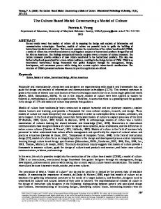
Method for Constructing Performance Annotation Model Based on Architecture Design of Information Systems Hui Du^ Renchu Gan^, Kecheng Liu^' ^, Zhenji Zhang^ and Darren Booy^ ^ School of Economics and Management, Beijing Jiaotong University, Beijing 100044, P.R. China hdu(glbjtu.eduxn
[email protected] ^ School of Management and Economics, Beijing Institute of Technology, Beijing 100081, P.R. China
[email protected] ^ Informatics Research Centre, University of Reading, Reading RG6 6AY, United Kingdom
[email protected] [email protected]
Abstract. To forecast performance of architecture design of information system, we used a performance analysis model to directly get performance indexes, as well as performance annotation model to get performance parameters and facilitate construction of performance analysis model that is indispensable. At present, when constructing performance annotation model, UML Profile for Schedulability, Performance, and Time specification has been de facto standard used to attach performance parameters to UML diagrams. However, UML use case diagram and UML deployment diagram annotated are not powerful enough to model complicated interactions among actors and information system in the organization layer and among hardware resources in the hardware layer respectively. Moreover, based on the performance annotation model using UML diagrams. Coloured Petri Nets (CPN) has not yet been used to construct performance analysis model. Therefore, no steps for facilitating construction of CPN based performance analysis model are included in currently processes for constructing performance annotation model. For solving both deficiencies, in this paper, UML activity diagram is proposed to be annotated in both layers. Moreover, performance annotation model construction process including steps for facilitating construction of CPN based performance analysis model is also devised. Furthermore, the application of the proposed method in the initial architecture design of an online bookshop system is briefly specified. Keywords: Information system. Performance, Annotation model. Architecture design, UML
L INTRODUCTION "The performance of computer-based information system is the response time and throughput seen by their users, as well as observable quantities associated with the corresponding computers, i.e. resource utilizations and length of resource queues in the operating system." [1] Please use the following format when citing this chapter: Du, H., Gan, R., Liu, K., Zhang, Z., Booy, D., 2007, in IFIP International Federation for Information Processing, Volume 255, Research and Practical Issues of Enterprise Information Systems II Volume 2, eds. L. Xu, Tjoa A., Chaudhry S. (Boston: Springer), pp. 1179-1189.
1180
Hui Du, Renchu Gan, Kecheng Liu, Zhenji Zhang and Darren Booy
It is the fact that severe performance problems have always emerged in implemented information systems. However, at that moment, it was usually very difficult for them to be rectified. To avoid this dilemma, architecture-oriented modeling and analysis of information systems performance was proposed especially in [1-3]. In [3], through analysis and synthesis of the model architectures respectively proposed in [1, 2, 4, 5], a new model architecture for architecture-oriented modeling and analysis of information systems performance was proposed, which is shown in table 1. Table 1. The New Model Architecture
Organization layer Software layer Hardware layer
Annotation view Organization annotation model Software annotation model Hardware annotation model
Analysis view Organization analysis model Software analysis model Hardware analysis model
Just as shown in table 1, the new model architecture consists of two parts, which are annotation view in the second column and analysis view in the third column. Both views are divided into three same layers, which are organization layer, software layer and hardware layer from the top down. Six models exist in the intersections of views and layers. Three models in the annotation view, in other words performance annotation model, are used to get performance parameters and facilitate construction of corresponding three models in the analysis view, in other words performance analysis model, which are used directly to get performance indexes through analysis or simulation. Each two models in each layer from the top down are used to model interactions respectively among actors and information system, among software processes and among hardware resources. Since UML Profile for Schedulability, Performance, and Time specification (in short SPT Profile) was adopted by OMG in 2002, it has been de facto standard used to attach performance parameters to UML diagrams in most performance engineering studies. For example, in [4, 6, 7], UML use case diagrams were annotated by the performance extensions defined in SPT Profile [8] to specify workload related parameters in the organization layer. UML activity diagrams were annotated to specify scenario related parameters in the software layer. UML deployment diagrams were annotated to specify hardware resource related parameters in the hardware layer. In addition, in [9], UML sequence diagrams were also annotated to specify scenario related parameters in the software layer. As to construction of performance analysis model, some different languages have been used. For example, multi-class queuing network was used in [4, 7] and stochastic Petri nets was used in [6, 9]. Although SPT Profile has been de facto standard used to attach performance parameters to UML diagrams, deficiencies still exist in UML diagrams annotated. As we know, UML use case diagram is mainly used to get functional requirements of information system, it is too simple to model complicated interactions among actors and information system in the organization layer. UML deployment diagram is in fact a kind of static diagram, which is mainly used to specify distributions of software processes or components and hardware resources of information system. Therefore, it
Method for Constructing Performance Annotation Model Based on Architecture Design of Information Systems 1181 is really unsuitable to use it to model complicated interactions among hardware resources in the hardware layer. Based on the performance annotation model using UML diagrams, although different languages have been used to construct performance analysis model, CPN [10] has not yet been used. In fact, compared with all kinds of queuing networks, CPN can model synchronization at ease. Compared with stochastic Petri nets, there is less restrictions on CPN transition. Furthermore, based on the performance analysis model using CPN, Design/CPN, a computer tool, can be used to get performance indexes through simulation. To sum up, CPN is indeed a suitable language to be used to construct performance analysis model. However, since CPN has not yet been used, no performance annotation model construction process including steps for facilitating construction of CPN based performance analysis model has been proposed. In order to solve both deficiencies discussed above, in this paper, UML activity diagram is proposed to be annotated both in the organization layer and in the hardware layer. Moreover, performance annotation model construction process including steps for facilitating construction of CPN based performance analysis model is devised. Furthermore, application of the proposed method based on the initial architecture design of an online bookshop system is briefly specified. The paper is organized as follows: in section 2, the method for constructing performance annotation model based on architecture design of information system is presented. In section 3, application of the method based on the initial architecture design of an online bookshop system is briefly specified. In section 4, conclusion and future work are provided.
2. METHOD FOR CONSTRUCTING PERFORMANCE ANNOTATION MODEL The method proposed in this paper consists of two parts, which are UML diagram for constructing performance annotation model and process for constructing performance annotation model.
2.1 U M L Diagram for Constructing Performance Annotation Model As stated in section 1, since it is unsuitable to use UML use case diagram and UML deployment diagram to model complicated interactions in the organization layer and in the hardware layer respectively, new UML diagram has to be chosen. In SPT Profile, two kinds of UML diagrams, which are UML activity diagram and UML sequence diagram, are used to be annotated in the software layer. Compared with UML use case diagram and UML deplo)mient diagram, though they can both model complicated interactions, "when it comes to model complex hierarchical scenarios, UML activity diagram has some significant advantages due to both its conceptual base and also to its notational convenience" [8]. According to table 1, since performance annotation model has three layers, UML activity diagram is chosen to be annotated in all three layers in this paper.
1182
Hm Du, Renchu Gan, Kecheng Liu, Zhenji Zhang and Darren Booy
2.2 Process for Constructing Performance Annotation Model Since UML activity diagram is chosen to construct performance annotation model and CPN is chosen to construct performance analysis model, new performance annotation model construction process including steps for facilitating construction of CPN based performance analysis model should be proposed. Moreover, according to table 1, since performance annotation model consists of three sub-models, its construction process should also consist of three sub-processes and each sub-model corresponds to each sub-process. Furthermore, since three sub-models have fixed order from the top down, the using sequence of the three sub-processes should also comply with the same order. 2.2.1 Sub-process for Constructing Organization Annotation Model Starting from the UML activity diagrams modeling key performance scenarios describing interactions among actors and information system in the organization layer, the sub-process for constructing organization annotation model consists of two steps, which are "attaching performance parameters to the UML activity diagrams" and "transforming transitions into object flows". According to [5], "The key performance scenarios are those that are executed frequently or those that are critical to the perceived performance of the system". The aim of the first step is to get organization related performance parameters. The activity based approach defined in [8] is used in this step to attach parameters to the UML activity diagrams. The aim of the second step is to facilitate construction of CPN based organization analysis model. Three operations are included in this step, which are: "transforming transitions between action states in actor swimlanes and activity states in information system swimlane into actor request object flows", "assigning state 'to be dealt with by processes' to actor request objects in the object flows from action state to activity state", and "assigning state *has been dealt with by processes' to actor request objects in the object flows from activity state to action state". When constructing CPN based organization analysis model, all actor request objects will be directly transformed into two socket places according to their states. 2.2.2 Sub-process for Constructing Software Annotation Model Starting from the UML activity diagrams modeling key performance scenarios describing interactions among processes in the software layer and referring to the organization annotation model constructed, the sub-process for constructing software annotation model consists of three steps, which are "attaching performance parameters to the UML activity diagrams", "supplementing actor request objects" and "supplementing process request objects". In fact, each UML activity diagram annotated is the decomposition of the corresponding activity state in the organization annotation model. The aim of the first step is to get software related performance parameters. The activity based approach defined in [8] is also used in this step to attach parameters to the UML activity diagrams.
Method for Constructing Performance Annotation Model Based on Architecture Design of Information Systems 1183 The aim of both the second step and the third step is to facilitate constraction of CPN based software analysis model. Three operations are included in the second step, which are "supplementing the same actor request object depending on an activity state in the organization annotation model to depend on the first activity state of the corresponding UML activity diagram", "supplementing the same actor request object depended on by the activity state in the organization annotation model to be depended on by the last activity state of the UML activity diagram", and "repeating operation one and two until all UML activity diagrams have been dealt with in the same way". When constructing CPN based software analysis model, all actor request objects supplemented will be directly transformed into two port places according to their states. In CPN, it is hierarchical relationship that between socket place and port place. Four operations are included in the third step, which are: "supplementing one process request object, which is depended on by the first activity state of an UML activity diagram and has the same name with the activity state and has state 'to be dealt with by processor"', "supplementing one process request object, which depends on the last activity state of the UML activity diagram and has the same name with the latest activity state and has state 'has been dealt with by network'", and "supplementing two process request objects for each other activity state of the UML activity diagram, of which one having the same name with the activity state and having state 'to be dealt with by processor' is depended on by the activity state and another having the same name with the latest activity state and having state 'has been dealt with by network' depends on the activity state", and "repeating operation one to three until all UML activity diagrams have been dealt with in the same way". When constructing CPN based software analysis model, all process request objects will be directly transformed into two socket places according to their states. 2.2.3 Sub-process for Constructing Hardware Annotation Model In order to use UML activity diagram to construct hardware annotation model, referring to the queuing network based system execution model of a web based application in [5], a UML activity diagram based hardware resource interaction template shown in figure 1 is firstly proposed. : process request [to be dealt with by processoF)
m^(^ : processor [free]
D
T^
{PAtype=$F»l
: prpcess request [has been dealt N/iHth by netv/ork)
• process request [to be dealt with by disk)
c
disk deals vinth process request
3
: process request [to be dealt with by network} (PAtypi (SN.-Mbps
{PAIypw=$0) L
I^
-c
letsvork deals v^th ,s request
> ^
Figure 1. The Hardware Resource Interaction Template Just as shown in figure 1, when a process request object sent by an activity state in the software annotation model enters the hardware layer, firstly, it waits to be dealt with by a processor. As soon as the processor isfi"ee,it is dealt with. Then, it waits to be dealt with by a disk. As soon as the disk isfi-ee,it is dealt with. Finally, it waits to
1184
Hui Du, Renchu Gan, Kecheng Liu, Zhenji Zhang and Darren Booy
be dealt with by a network. As soon as the network is free, it is dealt with. Moreover, three UML notes elements are used to specify types of processor, disk and network. Starting from the UML deployment diagram modeling distributions of software processes or components and hardware resources of information system and referring to the hardware resource interaction template as well as the software annotation model constructed, the sub-process for constructing hardware annotation model includes one step, which is "getting hardware resource interaction diagrams". In fact, each hardware resource interaction diagram gotten is the decomposition of the corresponding activity state in the software annotation model. Five operations are included in the step, which are: "assigning the same name of a process request object depended on by an activity state in the software annotation model to all process request objects in the hardware resource interaction template", "specifying names of all hardware resource objects dealing with the process request objects", and "assigning the same name of the hardware resource object to the swimlane including the object", and "assigning values to variables included in the three notes elements", and "repeating operation one to four until all activity states in the software annotation model have been dealt with in the same way". In the step, the aim of operation one to three is to facilitate construction of CPN based hardware analysis model and the aim of operation four is to get hardware related performance parameters. When constructing CPN based hardware analysis model, all process request objects with state "to be dealt with by processor" or "has been dealt with by network" will be directly transformed into two port places according to their states. All process request objects with state "to be dealt with by disk" or "to be dealt with by network" will be directly transformed into two places according to their states. All hardware resource objects will be directly transformed into other three places according to their classes. All action states will be directly transformed into three CPN transitions according to their names.
3. METHOD APPLICATION In order to validate the method proposed, it was used to construct performance annotation models of an online bookshop system based on its different architecture designs. In this section, only the application of the method based on the initial architecture design of the system will be briefly specified. 3.1 The Initial Architecture Design of the Online Bookshop System According to the method, since only the UML activity diagrams modeling key performance scenarios and the UML deployment diagram modeling distributions of software processes or components and hardware resources are necessary, therefore, only these diagrams of the initial architecture design of the online bookshop system will be specified below. In figure 2, the UML activity diagram modeling the initial key performance scenario describing the interactions between customer and the system is illustrated.
Method for Constructing Performance Annotation Model Based on Architecture Design of Information Systems 1185 In figure 3, the UML activity diagram modeling the initial key performance scenario describing the interactions among processes iexplore.exe, inetinfo.exe and sqlservr.exe is illustrated. In fact, figure 3 is the decomposition of the activity state "Deal with catalog and booklist request" in figure 2. Because of the page limitation, other two UML activity diagrams, which are the decompositions of other two activity states in figure 2 are omitted here. : Customer
c
: O n l l n * bookshop svxt*n DealwithKoTnJepagB
Birowse homepage
N
>
^
c c
Siibznit catalog axuH>ooklist reqiusst ' Oeal -vfrdth catalog azui ~ ^ booklist request y
Bro'w^e catalog axid l^ooKlist
Inas ixtterosteti laooK]
/""^
BiTovtrse b o o k , d e t a i l
'SC
^=
\Lf C doesn'tb u y ]
m>^
Figure 2. The Interactions between Customer and the System ; sqlservr.exe
: iexptote.exe
K
^ N., \ ^ Sdjmil book dBtail igq|T»sl y «PAstBp» Bitwrae book 8n'D3.^)J} ||PAdemaf«^sr';mean'i2,lw)
\
receive exectiint lesul of catalog request and eieole: busBtess Ipqic of bipklsl reqjesl • process request ' e*ecjedalal09t(rf
|[tobedeallwllib)(processo(| f
«PAslep» pfesentcatalog
jhasbeendeallwIhbTnelvrortj
business Iwc of booltisl regoesl • pwcess regijesl {[has been deaflwihtyiKhwHltl
(lMfJtnsrVr«»"JD3.Vns)).
request and booiitel request process request> [
receM eiecution restit of epilog request and eiecute
e»e(Ule business loipccibocMrst request .
N
P^rtOp=(faesy?>sr>eifl',9;iiis)),
recew execution results otbolh catalog
emttedaia bqc ofcalateq^equest process request
has been dealt with by netmrk)
[WKi'ms[">tjn'j03;ms))l |{PAdem3n(Krasr.^n':22,>rB)
Onsf','niean'2?,'nts)), |(lWJmst>arr'32.'ms)}]
execult data kxiiccJcaialDq request :prM:ess request
PAe(tOp{*lBsjs',fpsr','fnejii"5,>ns)),
}"n2>s)).
^
«PAstejP>
-X
\^P^itOp=ftesys-
bootfel request /
(WN'^hisr\>nean-3.2;ms]))
KtcJe data loqc af bocltbsi request process requesl [to be ijeal will by processor]
1 recene emutttmesdls of bcth catalog
caialoq and booHist request: actoi request
request and booldrsl request: process rei^est I has been dealt Mth by processes|
||tobedeatwitlibypiocessoi|
eimie dsla logic ofbooklisl request process requesl has been dealt with by netwcrit)
Figure 6. The Corresponding Part of Initial Software Annotation Model of the System
^ttkb«A|i)it&a«4) s w t a ^ m w i i u ^ {tHntaw
execute businesstoqicof cataloq request process request
process request
j
I
process request
J
f
Web & Application sewer processor: processor
Web &.Apprication server disk ; disk
[free]
[free]
|
execute business loqic of catatoq request process request
->
Po be dealt wrth by disk]
{PAtype=Penlium t \ tll800I^Hi')
IA».
'(A.m.
>
[to be dealt wrth by processoij
W -\
«U>&j^>pSc;tSMit»«
execute business loqic of cataloq request process request
[to be dealt with by network]
|{PAtype=lllti3 [\ Wide SCSI 9.16')
execute busirtess ioqic of cataloq request: process request [has been dealt wrth by network]
{PAlype-(10,
Tvlbps))
b.
1
[free]
/
f network c ^ process ealswith \ request j
•:J^ ^ ™
Figure 7. The Hardware Resource Interaction Diagram
4. CONCLUSION AND FUTURE WORK Since UML diagrams annotated and processes proposed are two primary deficiencies existing in current methods for constructing performance annotation model based on architecture design of information system, in this paper, UML activity diagram is proposed to be annotated both in the organization layer and in the hardware layer. Moreover, performance annotation model construction process including steps for facilitating construction of CPN based performance analysis model
1188
Hui Du, Renchu Gan, Kecheng Liu, Zhenji Zhang and Darren Booy
is devised. Furthermore, application of the proposed method based on the initial architecture design of an online bookshop system is briefly specified. Based on the initial performance annotation model constructed, the corresponding CPN based initial performance analysis model was constructed. Figure 8 illustrates the initial organization analysis model of the system, which was transformed fi*om figure 5. •—.ra ^ 1^ s
E i* i ^
iS| o
"«_ i ^
S-
^ -g " i
s.
ss
1".
t
S*
a,
=£
Figure 8. The Initial Organization Analysis Model of the System In figure 8, the socket place "tbd" was transformed directly from all actor request objects with state "to be dealt with by processes" in figure 5. The socket place "hbd" was transformed directly from all actor request objects with state "has been dealt with by processes" in figure 5. Based on the initial performance analysis model, simulation was run in the Design/CPN. The performance indexes of the initial architecture design gotten from the simulation are illustrated in figure 9. S ^ §, ^
- A v e r a g e r e s p o n s e time - CI>\J of ^V e b & ^Application s e r v e r - H a r d disk of A?Vet> &
120 lOO
- H a r d disk of I>B s e r v e r time slice(min) 0-2
(S-8
8-10
10-12
12-14
Figure 9. The Performance Indexes of the Initial Architecture Design Following the same process, performance indexes of different architecture designs of the online bookshop system were also gotten and the architecture design meeting performance objectives was finally identified and chosen. However, all performance indexes gotten from simulations have not yet been validated by a working system. It is the urgent work to be done in the near ftiture.
Method for Constructing Performance Annotation Model Based on Architecture Design of Information Systems 1189
REFERENCES 1. 2. 3.
4.
5. 6.
7.
8.
9.
10.
A.L. Opdahl, Performance Engineering during Information System Development (Institutt for Datateknikk of Telmatikk: Trondheim, 1992). Z. Yan, Dynamic Performance Modeling and Analysis of Information System Based on Colored Petri Net. Ph.D Thesis, Beijing Institute of Technology (2001). H. Du, R. Gan, K. Liu, and Z. Zhang, A Framework for Architecture-Oriented Modeling and Analysis of Information Systems Performance, in the Proc. of the 3^"^ International Conference on Wireless Communications, Networking and Mobile Computing, IEEE (Forthcoming, 2007). S. Balsamo and M. Marzolla, Performance Evaluation of UML Software Architectures with Multiclass Queuing Network Models, in Proc. of the 5th International Workshop on Software and Performance (ACM Press: New York, 2005), pp.37-42. C.U. Smith and L.G. Williams, Performance Solutions: A Practical Guide to Creating Responsive, Scalable Software (Addison Wesley: Boston, 2001). S. Distefano, M. Scarpa, and A. Puliafito, Software Performance Analysis in UML Models, in Proc. of the 2005 Workshop on Techniques, Methodologies and Tools for Performance Evaluation of Complex Systems (IEEE Computer Society: Washington, DC, 2005), pp.115-125. S. Balsamo and M. Marzolla, Efficient Performance Models in Component-Based Software Engineering, in Proc. of the 32nd EUROMICRO Conference on Software Engineering and Advanced Applications (IEEE Computer Society: Washington, DC, 2006),pp.64-71. Anonymous, UML Profile for Schedulability, Performance, and Time specification. Object Management Organization (2005). http://www.omg.org/docs/formal/05-01-02.pdf (Accessed July 14, 2007). M. Woodside, D.C. Petriu, D.B. Petriu, H. Shen, T. Israr, and J. Merseguer, Performance by unified model analysis (PUMA), in Proc. of the 5 th international workshop on Software and performance (ACM Press: New York, 2005), pp. 1-12. K. Jensen, Coloured Petri Nets: Basic Concepts, Analysis Methods and Practical Use Volume I (Springer: Berlin, 1992).