Computer Methods in Biomechanics and Biomedical Engineering
ISSN: 1025-5842 (Print) 1476-8259 (Online) Journal homepage: http://www.tandfonline.com/loi/gcmb20
Method for the estimation of a double hinge kinematic model for the trapeziometacarpal joint using MR imaging P. Cerveri , E. De Momi , M. Marchente , G. Baud-Bovy , P. Scifo , R.M.L. Barros & G. Ferrigno To cite this article: P. Cerveri , E. De Momi , M. Marchente , G. Baud-Bovy , P. Scifo , R.M.L. Barros & G. Ferrigno (2010) Method for the estimation of a double hinge kinematic model for the trapeziometacarpal joint using MR imaging, Computer Methods in Biomechanics and Biomedical Engineering, 13:3, 387-396, DOI: 10.1080/10255840903260818 To link to this article: http://dx.doi.org/10.1080/10255840903260818
Published online: 02 Oct 2009.
Submit your article to this journal
Article views: 124
View related articles
Citing articles: 9 View citing articles
Full Terms & Conditions of access and use can be found at http://www.tandfonline.com/action/journalInformation?journalCode=gcmb20 Download by: [Politecnico di Milano Bibl]
Date: 24 February 2017, At: 02:35
Computer Methods in Biomechanics and Biomedical Engineering Vol. 13, No. 3, June 2010, 387–396
Method for the estimation of a double hinge kinematic model for the trapeziometacarpal joint using MR imaging P. Cerveria*, E. De Momia, M. Marchentea, G. Baud-Bovyb, P. Scifoc, R.M.L. Barrosd and G. Ferrignoa a Bioengineering Department, Politecnico di Milano, Piazza Leonardo da Vinci 32, I-20133 Milan, Italy; IIT Network Research Unit of Molecular Neuroscience, Faculty of Psychology, San Raffaele Vita-Salute University, San Raffaele Foundation, via Olgettina 58, I-20132 Milan, Italy; cNuclear Medicine Department and CERMAC, San Raffaele Scientific Institute, via Olgettina 58, I-20132 Milan, Italy; dLaborato´rio de Instrumentac¸a˜o para Biomecaˆnica, Faculdade de Educac¸a˜o Fı´sica, Universidade Estadual de Campinas, Campinas, Brazil b
(Received 17 June 2009; final version received 14 August 2009) In this paper, we propose a method to estimate the parameters of a double hinge model of the trapeziometacarpal joint (TMC) by MRI-based motion analysis. The model includes two non-orthogonal and non-intersecting rotation axes accounting for flexion –extension (F – E) and adduction– abduction (A– A). We evaluated the quality of the estimated model parameters in the prediction of the relative motion of the first metacarpal bone with respect to the trapezium. As a result, we obtained that: (a) the estimated location and orientation of the F– E and A – A axes were in agreement with previous in vitro studies, (b) the motion of the first metacarpal predicted by the 2 degrees of freedom (2DoF) model exhibits a maximum surface distance error in the range of about 2 mm and (c) four thumb postures at the boundary of the TMC range of motion are sufficient to provide a good estimation of the 2DoF TMC kinematic model and good reproducibility (, 1.7 mm) of the real thumb motion at TMC level. Keywords: trapeziometacarpal joint; thumb kinematics; MR imaging; bone coordinate frame
Introduction Thumb opposability and strength is fundamental for object manipulation (Kapandji 1981). Since clinicians commonly consider the thumb responsible for at least 50% of overall hand function (Colditz 1990), it is crucial to investigate kinematic models of the thumb able to represent overall motion with particular interest in the trapeziometacarpal joint (TMC; Yoshida et al. 2003; Miura et al. 2004). The 3D movements of the thumb, involving flexion –extension (F –E), adduction– abduction (A– A), prono-supination (P –S) and composite motions (opposition and circumduction) are the effect of the interaction of specific anatomical structures at the TMC joint level, namely the trapezium and the first metacarpal bone under the constraints of ligament actions (Cooney et al. 1981; Kapandji 1981; Bettinger et al. 2000). Nonetheless, the TMC joint kinematics are still not completely understood as its ability to produce F –E, A – A and P– S movements seems mainly due to only 2 degrees of freedom (2DoF). Results on cadavers showed that concurrent F– E and A – A motion patterns can describe the overall TMC joint motion about two non-perpendicular and non-intersecting rotation axes (Hollister et al. 1992; Imaeda et al. 1994). According to such previous in vitro studies, it is reasonable to assume that, for a given F – E and A –A, the TMC joint expresses a unique P –S. Investigations on
*Corresponding author. Email:
[email protected] ISSN 1025-5842 print/ISSN 1476-8259 online q 2010 Taylor & Francis DOI: 10.1080/10255840903260818 http://www.informaworld.com
universal joint models (orthogonal and intersecting axes) showed that such a model is unsatisfactory to replicate the correct physiological motion of the TMC joint (Katarincic 2001; Valero-Cuevas et al. 2003; Cerveri et al. 2005). In Valero-Cuevas et al. (2003), the accuracy of the results of the dynamics analysis, in terms of forces and torques, was very sensitive to small deviations of the location and direction of such axes, even in the presence of accurate assessment of the musculo-skeletal parameters. In Santos and Valero-Cuevas (2006) the authors found, through simulated experiments, that two non-orthogonal and non-intersecting axes can be more effective in the kinematic modelling of the thumb at TMC level. In Cerveri et al. (2008), the authors proposed a methodological framework to estimate in vivo the parameters of such a 2DoF kinematic model through the processing of the 3D trajectories of markers attached to strategic points on the thumb surface. The results proved high parameter repeatability and the ability to reproduce the TMC joint motion with superior accuracy with respect to the one obtained by using a universal joint model. Concurrently, Chang and Pollard (2008) compared 2DoF and 3DoF kinematic models for the TMC joint including the P – S as an active DoF and utilised surface markers to estimate the model parameters. They reported that the 3DoF showed an improved prediction over the 2DoF model.
388
P. Cerveri et al.
Both works, however, lacked a direct validation on bone surface (BS) data. 3D imaging is an emerging methodology for analysing hand and wrist kinematics. CT scanning data were proposed to study the small bone kinematics in multiple wrist/forearm postures (Crisco et al. 2005; Moore et al. 2007). However, the intrinsic invasiveness prevented large use of this approach. MR imaging of the hand was utilised to study: the torque arms and tendon lines of action for the index finger (Fowler et al. 2001), the pathological changes in the hand motion in patients with rheumatoid arthritis (Andrysiak et al. 2000), the surface marker placement and the skin movements with respect to flexional bone motion (Ryu et al. 2006) and the in vivo contact mechanics in the human wrist during an active light grasp (Pillai et al. 2007). Conversely, none of these studies focused on the use of MRI to analyse the finger kinematics and to validate kinematic models of the joints in the hand. Two main reasons prevented the kinematics analysis based on MRI: (a) any consistent study requires several 3D postures such that the full RoM of the analysed joint is adequately sampled and (b) MRI is not well suited for bone image analysis and particular acquisition setups are needed, other than the ones used in clinical diagnostics, to increase the signal to noise ratio of the skeletal tissue and improve the segmentation. In this paper we propose a method for computing the 2DoF TMC kinematic model through MRI-based motion analysis from a number of postures of the thumb acquired through a 3T MRI scanner. Our purpose was to evaluate the quality of the estimated model parameters in the prediction of the relative true motion of the first metacarpal bone with respect to the trapezium. The results were compared with those from the external marker-based analysis processing the positions of MRI opaque markers.
These were attached to the hand surface, and reconstructed in the MRI volumes as to simulate an optical capture. Finally, we analysed the minimum number of strategic postures that guarantee a satisfactory quality of the model parameter estimation and prediction capability.
Materials and methods Acquisition protocol One male volunteer (age: 40, mass: 77.5 kg, height: 180 cm, Caucasian race, right-handed, no trauma reported or degenerative disease of the hand or systemic pathologies disturbing motor function) was recruited. He signed the informed consent for motion analysis and MR acquisitions, according to forms approved by the Human Subject Committee of the San Raffaele Vita-Salute University (Milano, Italy). Nine plastic balls (5 mm diameter), filled with vitamin E, were glued in correspondence of strategic points on the surface of the right hand of the subject (Figure 1(a)). The hand of the subject was imaged with a 3T MRI scanner (Philips Achieva, Philips, The Netherlands) in conjunction with a eight channels head coil (Table 1). Twelve different thumb postures were acquired from the complete adduction in the palm plane to nearly the opposition posture. The thumb and the hand dorsum were leaned on semi-rigid foam casts and blocked by scotch-tape. Wrist stability was attained by placing the hand on a custom-designed wrist brace to maintain a certain radioulnar and F – E position of the wrist.
Image data processing In order to segment the images and generate 3D models of the first metacarpal, trapezium and radius bones, the 12 MRI digital datasets were converted from DICOM
Figure 1. One of the 12 postures with the surface markers attached to the skin (a). After image segmentation, the BSs were reconstructed (b). The reconstructed surfaces from the 12 hand MRI acquisitions (c).
Computer Methods in Biomechanics and Biomedical Engineering Table 1.
389
Acquisition setup for MRI.
MRI acquisition System Magnetic field strength Scanning protocol Time repetition/echo Flip angle Field of view Number of postures XY matrix size (resolution) Slice spacing Physical pixel size Bit per pixel
Philips Achieva 3T T1-weighted 3D turbo field echo 3.98/1.9 ms 88 190 £ 190 mm 12 256 £ 256 pixels 0.90 mm 0.86 £ 0.86 mm 16 bits/pixel
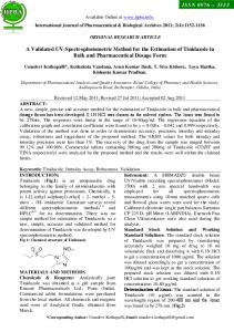
M5
1st metacarpal BCF Hand Dorsum TCF M4 F-E TCS
M9
Note: The average scan time for MRI was 6 min and 20 s for 120 slices.
M6
M2
A-A TCF M7
to analyse (Mayo Foundation for Medical Education and Research) format and imported into the computer-aided design software AMIRA 4.1 (Mercury Computer Systems, Chelmsford, MA, USA). The markers were automatically segmented by fitting circular contours, sampled from a sphere with known diameter (5 mm). The centroids of the markers were automatically computed as the centre of mass of the corresponding reconstructed spheres. The bone segmentation was performed by first analysing the distribution of the grey values of each bone across the slices. An initial threshold for each bone was chosen as the average value of the corresponding grey distribution. Owing to the different bone density and the thickness of the three bones, three different thresholds were found. The bone segmentations were then refined manually. After contouring the bones, the reconstruction of the surfaces (Figure 1(b),(c)) was obtained using the automatic functionalities provided by AMIRA. Coordinate frame definition Seven different coordinate frames were computed and referenced throughout this study. Two technical coordinate frames (TCFs) identified the F –E and the A –A axes. Two additionally TCFs identified the hand dorsum and the dorsal distal forearm using the corresponding marker triads. The dorsal distal forearm TCF, representing an anatomical coordinate system, was positioned at the ulnar styloid marker point. The X-axis of the dorsal distal forearm TCF was computed as the line joining the points at the radial (M1) and ulnar styloid (M2) bony processes. The Y- and Z-axis were derived from the X-axis, by applying the Graham – Schmidt orthogonalisation to the three points on the wrist. The hand dorsum TCF was needed to detach the thumb movements from the palm motion and was positioned at M4. The Z-axis of the hand dorsum CS was computed as the direction of the plane fitting M4, M5 and M6. The X- and Y-axis were derived from the (M4 – M6) direction, by applying the Graham – Schmidt orthogonalisation. Three local bone coordinate frames (BCF) were constructed for the first metacarpal
M1
M8 Trapezium BCF
M3
Radius BCF
Dorsal distal forearm TCF
Figure 2. Technical and anatomical coordinate systems utilised in this study.
bone, the trapezium and the radius, respectively, and determined according to Wu et al. (2005). In particular, the adoption of the radius BCF was motivated by the need to express the TCF of the F– E and the A –A axes with respect to the radius BCF (Figure 2). Surface data processing We assumed the MRI image coordinate system for pose 1 (reference posture) as the global coordinate system. In order to evaluate the motion of the first metacarpal bone with respect to the trapezium, expressed in the radius CF, and to compute the kinematic model parameters of the TMC joint, a surface-based registration procedure, based on the iterative closest point (ICP) algorithm, was adopted (Besl and McKay 1992). As originally the 3D polygonal surfaces of the different postures had different poses in the global coordinate frame, the procedure involved sequentially: (1) registering the 11 radii to the radius of the reference posture, (2) transforming the 11 trapezii and first metacarpal bones by applying the registration transform computed in step 1, (3) registering the 11 trapezii to the trapezium of the reference posture, (4) transforming the 11 first metacarpal bones by applying the registration transform computed in step 3, (5) registering the 11 first metacarpal bones to the first metacarpal bone of the reference posture (these registration matrices represent the motion of the first metacarpal among different postures) and (6) extract corresponding points in all the first metacarpal surfaces to be utilised in the parameter
390
P. Cerveri et al.
estimation procedure. Specifically to this last step, three points were selected and utilised as virtual markers for computing the model parameters. Two points were located on the distal head at the lateral extremities of the condyles in the frontal plane. One point was located on the proximal head of the metacarpal bone in correspondence of the midpoint of the segment connecting the lateral extremities of the condyles in the frontal plane. In order to refer the first metacarpal motion with respect to the BCF of the radius in first reference posture, the computed registration matrices need to be expressed to the proximal BCF. Let DBCFj ;i and DBCFj ;k be the CF of bone j in posture i and the CF of bone j in posture k, respectively, expressed in the corresponding proximal BCF (radius: j ¼ 0, trapezium: j ¼ 1 and first metacarpal: j ¼ 2). For the radius, the proximal BCF is represented by the global coordinate system. The rigid transform T j;1i representing the relative movement of the bone j from posture 1 to posture i, expressed with respect to the proximal adjacent bone (for the first metacarpal we consider the trapezium, while for the trapezium we consider the radius) can be written as: T j;1i ðDBCFj21 ;1 Þ21 DBCFj ;1 ¼ ðDBCFj21 ;i Þ21 DBCFj ;i :
ð1Þ
Then T j;1i can be derived as follows: T j;1i ¼ ðDBCFj21 ;i Þ21 DBCFj ;i ðDBCFj ;1 Þ21 DBCFj21 ;1 : Setting up the BCF for each bone in pose 1, the coordinate frames for the other postures can be derived as follows: DBCFj ;i ¼ T reg_BCFj ;1i DBCFj ;1 ;
ð2Þ
where T reg_BCFj ;1k was computed by ICP registration of the bone j in pose 1 to the corresponding bone in pose i (Figure 3).
Tj,1i DBCFj,i
DBCFj,1
DBCFj–1,1
Treg_BCFj–1,1i
DBCFj–1,i
(ICP registration)
Figure 3. The relative motion of the first metacarpal (distal bone j) with respect to the trapezium (proximal bone j 2 1) between pose 1 and i. The proximal bone in pose 1 is registered into the corresponding bone in pose i using ICP algorithm.
Once the transformation matrix is calculated, the relative movement of the first metacarpal was first expressed in terms of the helical axis (Woltring et al. 1987). Then, we utilised the transform matrices to compute the 2DoF model parameters. Kinematic model estimation Let Pi and Pk be two homogeneous coordinate vectors of the same point of the first metacarpal surface in posture i and in posture k, expressed in the corresponding BCF of the first metacarpal bone. According to the motion transform (Equation (2)), Pi is transformed into Pk by: P k ¼ T reg_BCF2 ;ik P i ;
ð3Þ
where j ¼ 2 corresponds to the first metacarpal bone. Adding the 2DoF TMC model, the same motion transform can be expressed by the following equation: 21 P k ¼ D21 FE RFE D FE DAA RAA D AA P i ;
ð4Þ
where DFE and DAA are the 4 £ 4 matrices expressing the transformation between the first metacarpal BCF and F – E TCS and A – A TCS, respectively. R FE and RAA are the 4 £ 4 rotation matrices accounting for F –E and A –A rotations about the Z local axis of the corresponding TCS by a and b angles, respectively. Equation (4) depends on the position and the orientation of the F –E and A –A axes (10 independent model parameters) and the a and b angles (two motion parameters). This motion model assumes the application of the F – E rotation and the A – A rotation, sequentially. The general non-linear mathematical problem involves the estimation of the 10 parameters, along with the two angles for each thumb posture, by minimising the distance (prediction error) between the positions of the measured three surface points (virtual markers) and those predicted by the model. Thus, considering 12 available postures (the first posture is considered as the reference), the optimisation provided the position and the orientation of the two axes and the 11 pairs (a and b). To avoid dealing with a high-dimensional non-linear system, we approached the estimation problem within the evolution strategy (ES) framework presented in Cerveri et al. (2008). The method evaluates a posteriori (Figure 4) the quality of the actual solution in terms of prediction error, erms, and consequently, it adapts the mutation function in the parameter space in such a way to produce more effective solutions. The procedure involves the generation of offspring parameter sets by mutating the current parameter set. For all the elements (one element is a parameter set) in the population, erms is computed and accumulated for the following selection process. The parameter set associated to the lowest erms, is selected to become the parent in the next epoch of the evolution process. The mutation function
Computer Methods in Biomechanics and Biomedical Engineering
391
Start Update parameters of the mutation function
Generate new population
Parameter initialisation
For all elements Virtual marker data 1° metacarpal motion transforms
For all acquisition frames Inverse kinematics
Model error
Fitness no Selection
Is step size below threshold? yes
Stop
Figure 4. Flowchart of the evolutionary optimisation procedure that refines the parameters (position and orientation of the F– E and A –A axes) of the 2DoF TMC joint model. The procedure is based on the processing of the first metacarpal motion transforms to compute the inverse kinematics and utilise the virtual markers (taken on the first metacarpal BS) to compute the fitness. Two nested cycles are considered: the outer one is related to the fitness computation for all the parameter sets in the offspring population; the inner one is related to the fitness computation (model error) corresponding to the current parameter set by solving the inverse kinematics for each couple of thumb postures.
is adapted according to the covariance matrix adaptation method (Cerveri et al. 2001). We adopted the (1, l-ES) paradigm, which implies that a single parameter set (father) generates l sons in the offspring and, among them, only one is selected to become a father to the next evolution step. The evolutionary optimisation stops when the step size of the mutation function goes below a predefined convergence threshold. At each step of the iterative optimisation, the algorithm needs to compute the inverse kinematics. Given the actual F – E and A – A parameter set, the inverse kinematic problem consists in finding the optimal angle pair (a and b) that minimises
D FE R21 ðaÞD21 D AA R21 ðbÞD21 2 the difference FE FE AA AA T reg_BCF2 ;ik k. A direct algebraic solution was implemented to compute the two angles. By applying the same optimisation procedure with the three physical markers attached on the thumb surface, a different model parameter set was obtained. Specifically, the method utilised the algorithmic framework presented in Cerveri et al. (2008). In this case, the TCF of the F–E and A–A axes were computed with respect to the dorsal distal forearm TCF. We called BS and external markers (EM) the two parameter sets obtained from the evolutionary optimisation by using the BS and EM, respectively. The obtained BS and EM parameters were expressed in the radius BCF in the reference posture and in the dorsal distal forearm TCF in the reference posture, respectively (Figure 2). In order to compare the two estimated parameter sets, the EM parameter set (TCFs of the F–E and A–A axes) was expressed in the BCF of the radius in the reference posture.
Performance analysis The feasibility of the estimation of the two parameter sets was assessed in terms of surface distance error. Surface distance error was expressed by the indexes (RMS and maximum value) of the distribution of the Hausdorff distance1 (Aspert et al. 2002) computed between the first metacarpal surface in pose k and the first metacarpal surface moved, according to the determined model kinematics, from posture 1 to posture k. In order to analyse the more significant postures in determining the quality of the parameter, we performed an additional stage of parameter estimation utilising subsets of the 12 postures identified at the boundaries of the F–E and A–A range of motion. Three, four, five and six thumb postures were utilised and the evolutionary optimisation computed new parameter sets. The extrapolation error in correspondence of each new parameter set was expressed in terms of Hausdorff distance, computed on all the 12 postures.
Results The rigid motion of the first metacarpal bone, expressed in the trapezium coordinate frame, was computed first in terms of the helical axis. The first posture was chosen as the reference. Then, the relative motion of the first metacarpal bone in all the remaining postures was computed. The obtained helical axes were not intersecting, with minimal distances ranging from 1.5 to 18.2 mm (Figure 5).
392
P. Cerveri et al.
Figure 5. Helical axes representing the true motion of the first metacarpal bone with respect to the trapezium in the first reference posture. For sake of image clarity, only four poses are displayed (1, 8, 9 and 12).
The 2DoF model parameters, computed for BS and EM (Table 2 and Figure 6) provided similar axis location and orientation, very close axis inter-distance (, 5 mm) and comparable prediction error (BS: 0.98 mm; EM: 2.29 mm). The A –A axis, traversing the proximal head of the first metacarpal bone, was distal with respect to the F –E axis for both BS and EM. The F– E axis was approximately aligned with the second metacarpal, traversing the trapezium, located in the ulnar direction with respect to the A – A axis. The two axes (F –E and A – A) were skewed by an angle of about 1118 (BS) and 1168 (EM), respectively. The RoMs computed with BS and EM parameter sets were about 508 (F –E) and 408 (A – A), and 578 (F –E) and 51 (A –A), respectively, in agreement with the physiological condition that F –E RoM is greater than A – A RoM. The estimated parameters of the kinematic model were applied to compute the motion of the first metacarpal bone in following postures, from 1 to 12. The RMS and maximum values of the Hausdorff distance distribution Table 2. Results of the convergence of the parameter estimation. 2DoF model RMS (max) prediction error Axis distance A –A wrt F– E Axis angle F– E RoM A –A RoM
BS
EM
0.98 mm (1.89) mm 4.97 mm Distal 111.898 50.198 40.568
2.29 mm (3.65) mm 4.71 mm Distal 116.388 57.888 51.538
were 1.41 mm (2.01 mm) and 2.21 mm (3.41 mm) for BS and EM, respectively (Table 3). The inspection of the distribution of the postures in (F– E and A – A) space (Figure 7) leads to select postures 3, 6, 7 and 12 as the four most representative postures of the whole RoM. Posture 3 corresponded to maximal adduction and maximal extension. Posture 6 corresponded to maximal abduction and maximal extension. Posture 7 corresponded to maximal abduction and maximal flexion. Posture 12 corresponded to maximal adduction and maximal flexion. In order to increase RoM spanning, the posture sets (3, 5, 6, 7 and 12) and (3, 4, 5, 6, 7 and 12) were considered. Three postures (3, 6 and 12), partially spanning the TMC RoM, were also selected to analyse the extrapolation performance of the corresponding parameter set. After estimating the four parameter sets, the computation of Hausdorff distances leads to lower accuracy provided by the parameter set corresponding to three postures with respect to the others (Table 4 and Figure 8). The differences of the RMSE between 12 (1.41 mm), four (1.66 mm), five (1.48 mm) and six (1.44 mm) postures were lower than 0.30 mm. As the worst case, we chose (1, 2 and 3) and (1, 2, 3, 11 and 12) posture sets. The calculated Hausdorff distances (Table 5) showed a lower prediction capability demonstrating that the choice of the postures at the boundaries of the F –E and A – A RoMs is fundamental. Discussion and conclusions The purpose of the current study was to present a methodology for in vivo estimation of the parameters of the 2DoFs kinematic model of the TMC joint with non-orthogonal and non-intersecting axes using non-invasive MRI imaging and to compare it with a complementary methodology based on surface markers. The first result of the current study confirmed that the TMC joint is poorly modelled by a universal joint because the HAs, computed on the real first metacarpal bone in different positions, did not intersect each other (Figure 4). Since the HA inter-distance is more than 1 cm, pure rotational movement about a fixed rotation centre was excluded, as the instantaneous rotation centre of the movement should travel at least this distance. The assumption that F– E and A – A axes are located in the trapezium and in the first metacarpal bone, respectively, was verified for the analysed subject using both MRI image data and marker trajectory (Figure 3), as well (Hollister et al. 1992). The distance between the two axes, computed both with BS and EM, was about 5 mm in agreement with the results (2 – 5 mm) reported in Cerveri et al. (2008), and the ones reported (3.5 –5 mm) in Chang and Pollard (2008), but 1 – 2 mm greater than the results reported in Cheze et al. (2001).
Computer Methods in Biomechanics and Biomedical Engineering
Figure 6.
F– E and A– A axes for BS (a) and EM (b) parameter sets displayed in the first posture.
Results on the motion prediction capability showed that the model replicates the movement of the first metacarpal bone with accuracy comparable with that obtained from physiological bone motion. The prediction of the first metacarpal movement was affected by RMS error (Hausdorff surface distance) less than 1.5 and 3.0 mm for BS and EM parameter sets, respectively, starting from a reference value (ICP registration) in the range of 1 mm. The difference between bone-based and marker-based movements can be mainly explained by considering the presence of soft tissues between the external surface and the bones that invalidate the rigidity relation between the markers and the underlying skeletal frame (Kuo et al. 2003; Su et al. 2005; Ryu et al. 2006). Both these research groups proposed different techniques to account for skin movements by using two markers per Table 3.
BS EM
393
segment of each finger placed proximally and distally to each joint. In addition, the effect of age and laxity in the skin on the accuracy of EM can be relevant. One would presume that skin laxity would increase with age, and thus accuracy would decrease with age. However, the focus of this paper was not in analysing skin effects on the parameter estimation. Finally, we demonstrated that four postures are sufficient to compute a consistent kinematic model able to reproduce the real movement of the thumb at the TMC joint level. However, we showed the relevance of selecting postures distributed within the whole RoM of the TMC joint (Tables 4 and 5). The methodological approach used in this work to obtain BSs was based on MRI imaging. Bone segmentation from MRI as still far from being automatic, as bone
Hausdorff distances (mm) computed for BS and EM parameter sets. 1–2
2–3
3–4
4–5
5 –6
6–7
7–8
8– 9
9 – 10
10 – 11
11 – 12
0.89 1.21
0.93 1.33
2.01 3.41
1.54 2.73
1.42 2.30
1.08 2.46
1.69 2.95
1.62 1.82
0.75 1.20
1.98 2.32
1.63 2.54
394
P. Cerveri et al.
Figure 7. The 12 postures represented in the (F – E and A – A) 2D space. The first posture was considered in the origin. For the sake of clarity, we displayed only the surfaces of the poses 1, 3, 4, 6, 7 and 12.
grey values greatly vary with density and thickness. Rather than focusing on image processing, we worked on the parameters of the scanning sequence to enhance the contrast of the bone tissue on the images with respect to soft tissues. We utilised a T1-weighted 3D turbo field echo scanning protocol tuning the time repetition/echo, the flip angle and the field of view to 3.98/1.9 ms, 88 and 190 £ 190 mm, respectively. Segmentation thresholds were automatically obtained but, in order to obtain good
quality surfaces, manual refinement of the bone image segmentation was conducted. In conclusion, this paper proposes a method and a realistic model of the TMC joint for use in hand biomechanical models and to address some of the limitations of the traditional approach to the study of thumb kinematics. It is valuable as only a few MRI poses can be sufficient to obtain a good movement prediction of the TMC joint. The present study was not intended either
Table 4. Hausdorff distances (mm) computed for BS using three, four, five and six thumb postures for parameter estimation compared to the distances computed using all the 12 models. Poses 1–2 2–3 3–4 4–5 5–6 6–7 7–8 8–9 9 – 10 10 – 11 11 – 12 RMS (max)
BS (12)
BS (3) 3, 6 and 12
BS (4) 3, 6, 7 and 12
BS (5) 3, 5, 6, 7 and 12
BS (6) 3, 4, 5, 6, 7 and 12
0.89 0.93 2.01 1.54 1.42 1.08 1.69 1.62 0.75 1.98 1.63 1.41 (2.01)
1.63 1.73 2.56 1.8 1.62 1.83 2.75 2.11 1.65 2.66 2.34 2.01 (2.75)
1.22 1.28 2.26 1.7 1.63 1.45 1.8 1.62 1.1 2.37 1.87 1.63 (2.37)
1 0.96 2.18 1.53 1.52 1.18 1.72 1.63 0.83 2.04 1.72 1.48 (2.18)
0.97 0.98 2.11 1.56 1.46 1.08 1.74 1.62 0.74 2 1.7 1.44 (2.11)
Computer Methods in Biomechanics and Biomedical Engineering 12 poses
3 poses
4 poses
5 poses
395
6 poses
3
2.5
mm
2
1.5
1
0.5
0 1–2
2–3
3–4
4–5
5–6
6–7
7–8
8–9
9–10 10–11 11–12
Figure 8. Hausdorff distances (mm) computed for BS using three, four, five and six thumb postures for parameter estimation compared to the distances computed using all the 12 models. Table 5. Hausdorff distances (mm) computed for BS with postures (1, 2 and 3) compared to the distances computed for BS with postures (1, 2, 3, 11 and 12).
BS (1, 2 and 3) BS (1, 2, 3, 11 and 12)
1–2
2 –3
3–4
4–5
5 –6
6–7
7–8
8– 9
9 – 10
10 – 11
11 – 12
0.99 0.89
1.27 1.12
7.72 5.36
3.19 2.26
4.50 0.72
8.69 3.15
8.76 3.57
1.55 1.17
2.94 1.32
4.10 3.56
2.52 1.15
to provide a definitive model of the TMC joint as the 3D motion between the trapezium and first metacarpal should be measured in more poses and many more subjects would be required, or to propose methodologies for bone segmentation from MRI. In addition, it did not consider the relative movement of the trapezium with respect to the other carpal bones in the function of wrist F –E (Crisco et al. 2005). From the current data analysis, we thus summarised that: (a) in agreement with in vitro studies, the estimated F –E axis was approximately aligned with the second metacarpal and traversing the trapezium whereas the A – A axis was located at the base of first metacarpal bone, (b) the TMC model computed through EM motion compares favourably with the 2DoF model computed through BS motion, (c) the motion of the first metacarpal predicted by the 2DoF model exhibits a maximum surface distance error in the range of about 2 mm and (d) four thumb postures at the boundary of the TMC range of motion are sufficient to provide a good estimation of the 2DoF TMC kinematic model and good reproducibility of the real thumb motion at TMC joint level. Future works will be devoted to the assessment of the model parameters from multiple subjects acquired with MRI.
Note 1.
Given two surfaces A and B with different number of points, the Hausdorff distance between A and B is obtained as HðA; BÞ ¼ maxðhðA; BÞ; hðB; AÞÞ where h(A,B) ¼ max(min (d(a,b)) for all a in A, b in B, where d(a,b) is a L2 norm.
References Andrysiak R, Ciechomska A, Kro´licki A, Mianowicz J, Tłustochowicz W. 2000. MRI evaluation of pathological changes taking place in the hand in patients with rheumatoid arthritis. Ortop Traumatol Rehabil. 30;2(4):78 – 82. Aspert N, Santa-Cruz D, Ebrahimi T. 2002. MESH: measuring error between surfaces using the Hausdorff distance. Proceedings of the IEEE International Conference on Multimedia and Expo 2002 (ICME), vol. I. p. 705– 708. Besl PJ, McKay ND. 1992. A method for registration of 3D shapes. IEEE Trans Pattern Anal Mach Intell. 14(2): 239– 256. Bettinger PC, Smutz WP, Linscheid RL, Cooney WP, III, An KN. 2000. Material properties of the trapezial and trapeziometacarpal ligaments. J Hand Surg [Am]. 25: 1085– 1095. Cerveri P, Pedotti A, Borghese NA. 2001. Combined evolution strategies for dynamic calibration of video-based movements measurement systems. IEEE Trans Evol Comput. 5: 271– 282. Cerveri P, Lopomo N, Pedotti A, Ferrigno G. 2005. Derivation of centers and axes of rotation for wrist and fingers in a hand
396
P. Cerveri et al.
kinematic model: robust methods and reliability results. Ann Biomed Eng. 33(3):401– 411. Cerveri P, De Momi E, Marchente M, Lopomo N, Baud-Bovy G, Barros RML, Ferrigno G. 2008. In-vivo validation of a realistic kinematic model for the trapezio-metacarpal joint using an optoelectronic system. Ann Biomed Eng. 36(7):1268–1280. Chang LY, Pollard NS. 2008. Method for determining kinematic parameters of the in vivo thumb carpometacarpal joint. IEEE Trans Biomed Eng. 55(7):1897– 1906. Che`ze L, Doriot N, Eckert M, Rumelhart C, Comtet JJ. 2001. E´tude cine´matique invivo de l’articulation Trape´zome´tacarpienne. Chirurgie de la Main. 20:23– 30. Colditz JC. 1990. Anatomic considerations for splinting the thumb. In: Mackin EJ, Hunter JM, Callahan AD, editors. Rehabilitation of the hand: surgery and therapy. Philadelphia (PA): C.V. Mosby Company. Cooney WP, Lucca MJ, Chao EYS, Linscheid RL. 1981. The kinesiology of the thumb trapeziometacarpal joint. J Bone Joint Surg [Am]. 6:1371– 1381. Crisco JJ, Coburn JC, Moore DC, Akelman E, Weiss AP, Wolfe SW. 2005. In vivo radiocarpal kinematics and the dart thrower’s motion. J Bone Joint Surg [Am]. 87(12): 2729– 2740. Fowler NK, Nicol AC, Condon B, Hadley D. 2001. Method of determination of three dimensional index finger moment arms and tendon lines of action using high resolution MRI scans. J Biomech. 34(6):791– 797. Hollister A, Buford WL, Myers LM, Giurintano DJ, Novick A. 1992. The axes of rotation of the thumb carpometacarpal joint. J Orthop Res. 10:454– 460. Imaeda T, Niebur G, Cooney WP, III, Linscheid RL, An KN. 1994. Kinematics of the normal trapeziometacarpal joint. J Orthop Res. 12:197 – 204. Kapandji A. 1981. Biomechanics of the thumb. In: Tubiana R, editor. The hand. Philadephia (PA): W.B. Saunders Company. p. 404– 422. Katarincic JA. 2001. Thumb kinematics and their relevance to function. Hand Clin. 17:169 – 174. Kuo L-C, Cooney WP, III, Oyama M, Kaufman KR, Su F-C, An K-N. 2003. Feasibility of using surface markers for assessing
motion of the thumb trapeziometacarpal joint. Clin Biomech. 18:558 – 563. Miura T, Ohe T, Masuko T. 2004. Comparative in vivo kinematic analysis of normal and osteoarthritic trapeziometacarpal joints. J Hand Surg [Am]. 29:252 – 257. Moore DC, Crisco JJ, Trafton TG, Leventhal EL. 2007. A digital database of wrist bone anatomy and carpal kinematics. J Biomech. 40:2537– 2542. Pillai RR, Thoomukuntla B, Ateshian GA, Fischer KJ. 2007. MRI-based modeling for evaluation of in vivo contact mechanics in the human wrist during active light grasp. J Biomech. 40(12):2781– 2787. Ryu JH, Miyata N, Kouchi M, Mochimaru M, Lee KH. 2006. Analysis of skin movement with respect to flexional bone motion using MR images of a hand. J Biomech. 39:844– 852. Santos VJ, Valero-Cuevas FJ. 2006. Reported anatomical variability naturally leads to multimodal distributions of Denavit – Hartenberg parameters for the human thumb. IEEE Trans Biomed Eng. 53(2):155– 163. Su F-C, Chou YL, Yang CS, Lin GT, An KN. 2005. Movement of finger joints induced by synergistic wrist motion. Clin Biomech. 20:491 – 497. Valero-Cuevas FJ, Johanson ME, Towles JD. 2003. Towards a realistic biomechanical model of the thumb: the choice of kinematics description may be more critical than the solution method or the variability/uncertainty of musculoskeletal parameters. J Biomech. 36:1019 – 1030. Woltring HJ, de Lange A, Kauer JMG, Huiskes R. 1987. Instantaneous helical axes estimation via natural, crossvalidated splines. In: Bergmann G, Ko¨lbel R, Rohlmann A, editors. Biomechanics: basic and applied research. Berlin (Gemany): Springer. p. 121–128. Wu G, van der Helm FCT, Veeger HEJ, Makhsous M, Van Roy P, Anglin C, Nagels J, Karduna AR, McQuade K, Wang X, et al. 2005. ISB recommendation on definitions of joint coordinate systems of various joints for the reporting of human joint motion – part II: shoulder, elbow, wrist and hand. J Biomech. 32:1337– 1341. Yoshida R, House HO, Patterson RM, Shah MA, Viegas SF. 2003. Motion and morphology of the thumb metacarpophalangeal joint. J Hand Surg. 28(5):753– 757.