Inf Syst Front (2009) 11:75–86 DOI 10.1007/s10796-008-9143-y
Method of design and specification of web services based on quality system documentation Miladin Stefanovic & Milan Matijević & Milan Erić & Visnja Simic
Published online: 29 October 2008 # Springer Science + Business Media, LLC 2008
Abstract In this paper, we present a method for development and specification of web services based on the quality system documentation. The general assumption is that service oriented architecture is based on business services and these business services mostly correspond to exchanged documentation in a real business system. Documentation of a quality system is recognized in form of documents that describe business processes in a real business system and identify exchanged documentation with environment. Presented method uses documentation of quality system and documentation flow for web service specification. We developed the CASE tool for web service specification based on a new approach, and we compare it to other existing tools. Keywords Web service . Specification . DQMS
M. Stefanovic (*) : M. Erić Department of Industrial Engineering, Faculty of Mechanical Engineering, University of Kragujevac, Kragujevac, Serbia e-mail:
[email protected] M. Erić e-mail:
[email protected] M. Matijević Department of Automatic Control, Faculty of Mechanical Engineering, University of Kragujevac, Kragujevac, Serbia e-mail:
[email protected] V. Simic Institute for Physics and Informatics, Faculty of Science, University of Kragujevac, Kragujevac, Serbia e-mail:
[email protected]
1 Introduction Most companies have an environment of disparate legacy systems, applications, processes, and data sources, which typically interact by a maze of interconnections that are poorly documented and expensive to maintain (Douglas 2003). Additional problems arise from market consolidations in the digital age and new collaborative and business environment (Hagel and Brown 2001; Finkelstein 1993). In the beginning, the Web Services were mostly used in communication between companies and their distributed units (as well as in integration of supply chain management). Arsanjani A. et al. (2002) suggested that the main strength and advantage of the Web Services will be utilized in implementation inside companies, in solving issues of legacy system integration, or for supporting new processes. The Service-oriented Computing (SoC) is emerging as a promising paradigm for enabling the flexible interconnection of autonomously developed and operated applications within and across organizational boundaries (Alonso et al. 2003; Linthicum 2003). The technology behind the SoC trend is mainly based on the standards such as SOAP (Simple Object Access Protocol), WSDL (Web Service Definition Language), WS-Security (Web Service-Security), and BPEL4WS (Business Process Execution Language for Web Services). The Web Services provide a distributed computing technology for revealing the business services of applications on the Internet or intranet using the standard XML protocols and formats. The use of the standard XML protocols makes the Web Services platform, language, and vendor independent, and an ideal candidate for some solutions. The Web Services are promise to solve many different problems. They do not need to install on a local computer, they allow systems to operate in totally different environments, they interoperate using XML and other web standards.
DO09143; No of Pages
76
Inf Syst Front (2009) 11:75–86
Increasing demand for development and implementation of the Web Services increased need to solve different problems connected to design, development, implementation, security and the Web Services’ management. Creation of the Web Service applications is yet another complex task to add to the IT department's list. Ours experience suggests it is not enough to approach the Web Services development armed with documentation on just the underlying technologies, such as SOAP and WSDL. During the implementation process and usage of the Web Services, one can be faced with different problems connected to design, development, implementation, security and the Web Services management (Casati et al. 2001; Channabasavaiah and Holley 2004; Hogg et al. 2004). There are large number of techniques and approaches for surpassing existing problems. CBDi (Component Based Development and Integration) concept, developed by IBM gets even more importance with the emergence of the Web Service. Problems connected with the implementation of the Web Services Arsanjani A. et al. (2001) defined such as: & & & & &
Organizational (project management, training, changes in management), Methodological (need to improve existing methodologies in order to fully support SOA—Service Oriented Architecture), Problems connected with the architecture (the best practice and patterns for defining strong but flexible architecture to support the Web Services), Problems connected with the implementation technology (selection of the implementation technology), and Infrastructural problems and shortage of software tools (standards and CASE tools for SOA—Service Oriented Architecture).
Other authors and sources Wilfried et al. (2003) and Buhler et al. (2004) recognized following important problems in specification and implementation: &
&
The fact that some Web Services were designed without necessary analysis of the business processes and their position and place in complete architecture of information and a business system; Coordination of functioning of the Web Services, although the large number of steps were made in that direction such as definition of BPEL4WS—Business Process Execution Language for Web Services (merging XLANG—Microsoft and WSFL—Web Services Flow Language—IBM) and BPML (Business Process Modeling Language) with WSCL (Web Service Composition Languages) (Sun, SAP),
This paper will focus on problems of specification and modeling of the Web Services. Fensel and Busler (2002) presented WSMF (Web Service Modeling Framework),
conceptual model for development and description of the Web Services. WSMF consists of four main elements: ontology Fensel and Busler (2002; formal explicit specification)—provides terminology that is used by other elements; goal repository—gives description of problem that should be solved by the Web Services; description of the Web Service—definition of different aspects of the Web Services; and mediators—that solve problems of interoperability of the Web Services. Using this framework SWWS (Semantic Web Enabled Web Service) evolved with predominant task to define automated, ad-hoc interoperability between systems in order to fulfill business goals (Sheth and Meersman 2002). Many different methods for development of the Web Services emerged using more or less previously mentioned frameworks. One of the approaches for design and specification of the Web Services is Event Based Approach, Wilfried et al. (2003). This approach is directly based on OOA and OOD methodology MERODE, Wilfried et al. (2003). There are also other approaches based on AOCE (Aspect Oriented Component Engineering—Santokh S. et al. 2004) or CBD (Component Based Development—Barn 2004; Fu et al. 2003) for the Web Services development. Some approaches to implementation of the Web Services are based on patterns and use of POAD (Pattern-Oriented Analysis and Design—Buhler et al. 2004; Peltz 2003). IBM (Business, Integration, Composition, Custom, Application, Runtime patterns—IBM Corporation 2004) developed patterns for the Web Services as well as J2EE and Microsoft. There are large number of different approaches to specification and implementation of the Web Services as well as a large number of software and CASE tools such as: IBM Web Services ToolKit, MS Web Service ToolKit etc. The general idea of this paper is that service oriented architecture is based on business services, and that business services are mostly adequate to exchanged documentation in real business system. The documentation of quality system (DQS) is identified as appropriate approach for description of business processes in business system and identification of exchanged documentation with business environment. Quality Management Systems (QMS) is a collective term for methods and techniques developed to ensure the quality of products and processes in a company. It's usually represented as a formal set of process descriptions, procedures and routines that the company wants their employees to follow. General assumptions connected to DQS as a basis for development of web services: & &
DQS have to present processes in the business system. Documentation of quality system is on the second and third level: procedures, instructions, forms and reports are used.
Inf Syst Front (2009) 11:75–86
&
Documents must be developed according to appropriate ISO standards.
The definition of the original model for planning and specification of the Web Service, based on documentation of quality system is focus of this article. CASE tool for development and specification of the Web Service and WSDL code development is developed based on a new method.
2 Method for development and specification of web services Companies should start using the Web Services in internal application integration projects or legacy system integration. It is much easier to control, manage, find, execute, and maintain the Web Services within an intranet as compared to using them over the Internet. The main idea is providing an average company with methodological approach to identify possible business services and the Web Service. This method suggests development of the Web Services in following steps: &
&
&
&
Development of a matrix of documentation of quality system. The documentation of quality system could be divided in the following groups: procedures, directions, instructions, templates, and records. The matrix of documentation of the quality system connects procedures and records (e.g. processes and information that present input or output from those procedures). In the first step, the procedures are generalized as the Web Services, and input–output records as messages that the Web Service exchange with environment or as interfaces. Development of a communication matrix. Defines entities that take part in communication e.g. entities between documentation is exchanged. In this and previous step, the best beginning is using activity diagrams. From the previous matrix, we select a procedure and define the flow of templates and records to and from that procedure according to aspect of participants in communication. From the communication matrix, we extract the sequential diagrams for the Web Services, with defined scenarios for Web Services (Request/Response for example), operations and data types. Development of a data matrix, for a selected template/ record that is exchanged between two entities in communication, and based on previous matrix, exchanged data, and entities involved in creation and modification of that data are defined. The last step is implementation and development of summary description of the Web Service.
77
2.1 Development of a matrix of quality system documentation Modeling of a quality system is based on general concepts of processes and information and their connections on different level of decomposition. Connection between processes and information present information flow and they are determinate by role and importance of specific information for specific process. The documentation of a quality system (procedures, instructions, records and templates) present the basis for noticing of exchanged information between the processes. This fact could help in the Web Service development. Using the quality system and documentation of a quality system associative matrix of procedures and records could be created (Table 1). These matrixes are used for definition of logical architecture of system, which consists of subsystems and relation, and transformation in service oriented architecture. The subsystems are consisted of interconnected processes and information. These processes have very weak relation with other subsystems. The processes and information in the associative matrix are selected considering information flows and natural order of processes connected with those flows so the most of associations are grouped in square shape forms around the main diagonal of matrix. The main purpose of this matrix is: &
&
&
&
The definition of potential candidates for the Web Services (Each procedure is candidate for service if input or output documentation exist. The input documentation—documentation from environment “used” by procedure. Output documentation—documentation “produced” in procedure). The definition of potential interfaces between simple Web Services (in the case of a “neighborhood” procedure, a record produced in one procedure (as the result of the activities in the first procedure) and used in the second procedure as input, could be used for a definition of interface between simple services (or we can compose these two simple services in one Web Service). The definition of potential interfaces for legacy systems, i.e. legacy data base systems (in the case that data from a record is stored in data base or data from data base is used for definition of a record, then that specific record could be used for definition of interface for legacy system). The definition of a dialog between entities in business communication or between functional parts of the system.
2.2 Development of a communication matrix The next step is a definition of a communication matrix (Table 2). This matrix has entities in communication and
78
Inf Syst Front (2009) 11:75–86 Development (Qp TP 01)
Table 2 Communication matrix
(in) (in)
Sector of marketing and sale
Customer’s request for catalogue
C,M
Product catalogue (Qz MI 22) Customer’s request
Request, D
P-Qp MS 01 (Receive of request for catalogue), D, C-Qz MI 22, C,M,D
C,M,D
P, Qp MS 01 (Request of demand and analysis of completeness),D
C Create, P process, M modification, D delete
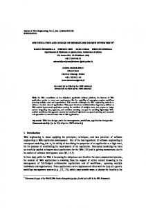
types of events as well as type of participation of entities in these events. This matrix enables identification of type of communication and defines approach to support that communication with the Web Services. More exactly, it defines processes in the real system and information support for those processes. Using this matrix “use case” diagrams (Fig. 1), that describe dynamics of system, could be defined. Figure 1 present a graphical overview of the functionality provided by a system in terms of actors, their goals, and any dependencies between those use cases, but communication matrix presents more clearly entities, actions and connection with real documentation of quality system: inputs in the system (Product catalogue Qz MI 22) and procedures. This matrix is based on DQS (Documentation of Quality System), and enables monitoring of changes of status of documentation and to monitor use case. In the first case, when we have entities from a company as sides in communication then we use documentation for definition of interfaces. In the second case, when documentation is exchanged between a business entity and environment, we can define methods or interfaces with the environment. In the
(ou)
(ou)
(ou)
Entities in communication Client
(in) (in)
Information from market or customers Plan of propaganda and commercial activities (Qo QA 01) Report from marketing and commercial activities (Qa MI 01) Catalogue of products (Qz MI 22) Customer’s demand Order Demand for a new product development
Commercial and Analysis of market propaganda (Qp MI 01) process (Qp MI 01)
Marketing and sale Information
Table 1 Matrix of quality system documentation
Processing and analysis of requests (Qp MS 01)
Development and sending of information
Product servicing
(in)
(ou)
Monitoring of Production delivery to customer (Qp PU01)
(in)
Exchanged documents
Fig. 1 Use case diagram
Inf Syst Front (2009) 11:75–86
79
third case, when record is defined using data from legacy data base, we can define interface with the legacy system. In this and previous step, some procedures become candidates for the Web Services and records become interfaces or messages.
Fig. 2 Sequence diagram
2.3 Development of a data matrix The third step is a definition of operation, using data matrix (Table 3). The data matrix present information in exchanged documents, e.g. it enables specification data for Web Service (it contains: operations, scenarios, parameters and types). The sequence diagrams (Fig. 2) are defined using this and previous matrix. This diagram shows how processes operate one with another and in what order (exchange of documentation between different sides: Operation: Product catalogue Qz MI 22, Scenarios: Catalogue Request/Catalogue Response). Using this information, we can make specification of the Web Service. 2.4 Implementation Using information from the previous steps as well as information about network ports, binding and protocols, the Web Services could be defined. The implementation approach and appropriate technology are selected using some implementation approach.
3 Case tool Q-WE for the web service development There is now widespread acceptance of the Web Services and service-oriented architectures. But despite the agreement on the key Web Services standards, there remain many challenges. Programming environments based on WSDL support go some way to facilitating the Web service development. The general idea for this CASE tool is to use documentation of quality system and activity diagrams as a basis for specification of Web Services and development of WSDL. The tool is a base on the previously presented model for specification of the Web Services based on DQS. This CASE tool is developed with three layer architecture. These selections ensure: openness to other data base
Table 3 Data matrix
management systems; portability, maintainability, lower costs, friendly user interfaces, software and hardware compatibility and easy integration with different products. The connection to a database is flexible ant it is possible to use different database management systems using just different connection strings in a data connection block. So this CASE tool could be used with different DBMS. The security and authorization of use of this software was achieved by a set of access rights to DBMS and authorization of access. There are two sets of rights: one full, which enables creates, reads, updates and deletes data, and other that enables just reading. Based on AS2 approach (Arsovski and Arsovski 1997; Arsovski et al. 2001), the documentation of a quality system could divide in the following categories: procedure, instruction, or direction (depending on complexity of activities and organizational level on which activities are defined or performed). These entities can be called procedures. From one procedure, we have one or more templates as an output. The procedures and templates are integral part of one scenario, for example: product development or marketing and sale. More functions and organization units from one company are employed in realization of one scenario. The next step is definition of phases and functions, and definition of elements of each scenario and definition of information about elements of scenario. During the distribution of a function in specific phases, we have to define activities, documents, additional elements and connection between elements as well as input of data. This method integrates BSP (Business Process Planning), HIPO (Hierarchy Input, Process Output) and SSA (Structured System Analysis), using documents of quality systems. Symbols, notation of AS2 approach are used in this CASE tool (Fig. 3). 3.1 Definition of scenarios
Operation
Scenario
Parameter
Product catalogue (Qz MI 22) Catalogue
Catalogue request Catalogue response
None Information
Type
Any URL, boolean, float, String, DataTime
The first step in work with this CASE toll is selection one oft two possible beginnings: a) definition and work with new project or b) work or modification of old projects (depending on the level of authorization). If we select a new scenario, the name of a scenario and selection of functions are the first inputs. If we select the old
80
Fig. 3 Notation, symbols of AS2. ①—Code, identification of activity (it also could be name of data base, document name, or archive name). ②—Document name (it also could be name of data base, decision making, name of document, Start/End of process, name of process control or name of archive). ③—Identification of responsible person (it also could be identification of responsible person for verification of specific document or activity)
scenario, we can change functions, and all other elements. Figure 4 depicts definition of one scenario definition. After selection of scenarios, the next step is definition of data flows using AS2 notation (Arsovski and Arsovski 1997; Arsovski et al. 2001). Using development environment depicted in Fig. 5, and symbols presented on left side Fig. 4 Definition of scenarios, development of new, or selection of old ones
Inf Syst Front (2009) 11:75–86
user could form diagrams. Using drag and drop technique, user arranges symbols on the working area and make connections between them (Fig. 5). The next step is definition of all parameters for each specific procedure or record. First user defines name, code and other general attributes of procedure (connection with other procedures and records). Procedure QpMI01 “Commercial and Propaganda” which defines activities in receiving customers request for catalogue and respond for that request is presented in Fig. 6. The service based on that procedure is called WSSale and has two operations: Catalog and Order. Both of these operations have input and output messages—IN Operation Catalog—record “Customer Request” and “Product catalogue (QzMI22)”, in operation Order—“Customer’s order”. After these activities user could go back to develop another scenario or define parameters that lead to development of the Web Services and development of WSDL code. This step corresponds to the first phase described in previous section: Development of a matrix of quality system documentation. In this step using the quality system and documentation of a quality system associative matrix of procedures and records are created. 3.2 Web Service development After definition of necessary parameters of procedures and records, user activates CASE tool for autonomy identification of possible Web Services and accompanied parameters for the Web Services. This CASE tool has two main potentials: the first one to make specification of the Web Services, support SOA and generate WSDL
Inf Syst Front (2009) 11:75–86
81
Fig. 5 Symbols and data flows (procedures and flows) for Marketing and sale scenario
code, and the second one to manage documents of quality system. Analyzing exchange of documentation between two entities, in presented case customer and marketing function, the software suggests the Web Services with messages that generally present records
Fig. 6 Definition of name, code and description of procedure
or information exchanged between customer and marketing. Users of this software toll could manually correct model or connect or divide specific Web Services and/or operation (and exchanged documentation between two procedures is used as a basis for definition of interfaces between services or legacy system). The beginning is definition of couples or messages exchanged between entities. The records become request/response messages and connection between neighboring procedures (with no interchange of structured documents) produce Web Service. Functioning of the tool is based on a model that was previously described that use definition of documentation, communication and data matrix. Web Service WSSale that has two operations (based on a specific procedure) and messages (based on accompanied structures or records) was developed in this example. Operation Catalogue in WSSale is presented in Fig. 7. This step is based on second phase: development of a communication matrix (Definition of names and general parameter (input/output) of documents of quality system—Operation CatalogueRequest). All presented data and information could be changed, modified or deleted manually. After this step, the large part of the Web Service is defined. Also this CASE tool keeps “map” of the Web Services. The next possible action in improvement of this CASE tool would be full visualization of the Web Service. In this version of Q-WS all services and operations are presented in the tables.
82
Inf Syst Front (2009) 11:75–86
Fig. 7 Definition of names and general parameter (input/output) of documents of quality system— Operation CatalogueRequest
3.3 Generation of WSDL code The next step is summary presentation of WSSale (this step is based on phase: development of data matrix). Initially, it was set values of scenario (Request/response); user could select style, header, and data types. The values of attributes all initially set in this example, Fig. 8. In this step, based on input and existing parameters, CASE tool develops part of WSDL code. These properties of Q-WS automate development of Web Service and domain of WSDL code development, and reduce or eliminate causes of errors in code. This tool could generate message headers and parts of messages using previously defined data fields, styles and other parameters. Input message with a part of headers and parameters in the body of messages is also defined as well as the output message. After the definition of parameters, it is possible to manually change some of these parameters (Fig. 9). This tool automatically creates some part of WSDL code. Some “standard” parts of WSDL code of web service are included such as: header, xsd types, input message, output message, definition of ports, binding, SOAP, definition of RPC. This automatically generated parts of WSDL code reduce possible errors that could appear in
manual code development. Of course, web service developer needs to specify of verify things like: name space, elements names, soap address location... After this, final step we have WSDL code (Fig. 10). The code stays in the associative connection with the Web Service, so we can manually change a part of WSDL code. 3.4 Characteristics and limitation of Q-WS CASE tool This tool has some advantages because enables the Web Service specification using documentation of quality system. Using these approach standard processes is used for basis for the Web Services. This tool shortens procedure of WSDL code development and eliminates possible errors in source code through development of some standard code components. This CASE tool is partly solving some of the problems that appear in SOA definition, such as: & & & & & & & & &
Fig. 8 Summary presentation of WSSale
Understanding and presentation of existing services, Presentation of needed information resources, Definition of needed interfaces and presentation of existing interfaces, Detailed presentation of process and their understanding, Definition of new services and information for integration with legacy systems, Definition or change of processes under influences of new services, Make easier implementation of new processes, Make easier selection of set of technologies and Enables testing and evaluation.
The main tasks for further development of this CASE tool would be addition of a graphical presentation of the sequential diagram and activity diagram of the Web Service, expansion and improvement of existing options and integration with environment and legacy systems.
Inf Syst Front (2009) 11:75–86
83
Fig. 9 Final adjustment of parameters
4 Comparative analysis of case tool Q-WS and other similar tools Software tools as well as other software solutions could be analyzed in many different ways (according performances, quality etc.). According to Boehms (1989), an evaluation of the level of software CASE tools could be performed according to Table 4. The software tools are ranked starting with ones just with the function of coding, editing and modification, up to the case tools that fully support processes Fig. 10 Part of generated WSDL code
or life cycles and could be integrated in the development environment. Each next level possesses all characteristics as previous level and set of own characteristics. Using this approach in evaluation of the software tools, we evaluation suggested Q-WS and available CASE tools in segments for definition, specification and support to the Web Services (Table 4). The analysis was performed using the available software products made by leading software developing companies, or leaders in specific fields of software development. There are a large number of
84
Inf Syst Front (2009) 11:75–86
Table 4 Comparative analysis of CASE tools CASE tools for Web Services and WSDL
Q-WS MapPoint Web Service SDK, IBM Web Services ToolKit XMLSpy® 2005 Stylus Studio 6 Panacea Software
Very low
Low
Normal
High
Very high
Code, edit, modification
Simple front end, back end, low integration
Basic of life cycle, medium integration
Strongly supported life cycle and medium level of integration
Strongly supported, proactive life cycle and high integration
X X X X X X
X− X X X X X−
X X X−
X X
X Existence, X− partial existence
software tools that support partial needs or functions. All listed, analyzed tools have options for coding, edit and modification of WSDL code. Map Point, IBM Web Service Toolkit and XML Spy have options for import and export of schemas, as well as validation, verification and documentation of Web Services. These tools support connection toward XML, XML/XSLT, SOAP. The place and abilities of CASE tool Q-WS is presented in Table 4. CASE tool Q-WS has lower level of detail, lower level of quality of user interface, and posses lower level of visualization, verification, and documentation of the Web Services. This case tool was developed by authors of this paper, so it could not be fully compared with commercial products of large software development companies. This tool has advantage because it enables integration with other web application and it is easy for on-line testing. This tool is making a step toward development of GUI for the Web Services (Kassoff et al. 2003). Q-WS has some advantage considering characteristics important for the Web Services, such as: detailed presentation of processes in company and understanding of processes, presentation of existing information resources, definition of needed resources of the Web Service development, planning and design of the Web Service.
Options for planning and design of the Web Services are the main advantage of Q-WS. Thanks to implemented method for specification and development of the Web Service, new Web Service could be easily specified and WSDL code automatically generated for that service. According to the presented analysis, Q-WS has one advantage comparing to other tools in the area of planning and specification of the Web Service, but in other areas it has lower quality than other commercially available software tools. Another survey was performed in order to evaluate quality of developed CASE tool. The quality of developed CASE tool was tested by questionnaire. Users of CASE tool (students, lecturers and software engineers from Faculty of Mechanical Engineering—46 persons) graded CASE tool according to suggested factors. These factors describe quality of software according to standard ISO/IEC 9126 (Table 5). Survey indicated that factor portability is high (software is developed using open source environment so it could fit to different environments). Other factors such as functionality, reliability, efficiency and maintainability are lower (this is new CASE tool with wide possibilities of improvement based on new approach). This tool could give important benefits in implementation of integration and engineering of legacy systems. Reengineering of information systems and integration of
Table 5 Survey results—evaluation of quality of software Factor Functionality—existence of a set of functions and their specified properties. Reliability—capability of software to maintain its level of performance under stated conditions for a stated period of time. Usability—effort needed for use, and on the individual assessment of such use, by a stated or implied set of users. Efficiency—relationship between the level of performance of the software and the amount of resources used, under stated conditions. Maintainability—effort needed to make specified modifications. Portability—ability of software to be transferred from one environment to another.
Grade (1–5, 5 the highs grade) 3.9 3.7 3.6 3.8 3.1 4.5
Inf Syst Front (2009) 11:75–86
legacy application could be successfully solved using the Web Services. On the other hand we can use the same documentation of the quality system and same flow of that documentation. This software tool can map existing resources and define possible interfaces to legacy system.
5 Conclusion The most important contribution presented in this paper is the model of specification and development of the Web Service based on the documentation of the quality systems. Three steps, staring with the matrix of the quality system documentation following with the matrix of communication and the matrix of data enable, specification and development of the Web Services. The general assumption is that service oriented architecture is based on the business service, and business services mostly correspond to exchanged documentation in the real business system. The documentation of the quality system is recognized as documents that describe business processes in the real business system and identify exchanged documentation with the environment. Presented model is different than existing models, because it is based on documentation of the quality systems. This model has some similarities with Event Based Approach. Events Based approach relies on separation of specific events and planning, specification and development of the Web Services based on those events and methods connected with specific events (where we have problem in definition of these events). The presented approach is based on the documentation of the quality systems, basically electronic equivalents of the real documents. Business documents and the documentation of the quality systems are reality and there are much easier for understanding. On the other hand, Component Based Development and Integration model starts with business processes and developed components not at basis. The presented model makes identification of business services easier. This model is based on the analysis of standardized documentation flow. CASE tool Q-WS is developed using the presented method. This software tool support specification and development of the Web Services and development of WSDL code. All standard options for edit, update and modification of WSDL code are available. This case tool was compared with representative software tools for development of the Web Services and WSDL. Presented CASE tool has disadvantage and lower level of quality of user interface, visualization, verification, and documentation. The general advantage of this case tool is: detailed presentation of processes in a company and understanding of the processes, presentation of existing information re-
85
sources, definition of needed resources of the Web Service development. The Web Services could help in different problem solving. Enterprises and, by extension, their ITs are composed of a wide variety of heterogeneous assets that businesses leverage as reusable shared services. The integration of the legacy systems could be much easier with the Web Services. The suggested method and CASE tool has the many advantage in this field. On the other hand, the Web Services could be used in different collaborative or Internet environments. The future work on CASE tool will be concern to the service flow and composition of complex web services, as well as quality and security of the Web Service.
References Alonso, G., Casati, F., Kuno, H., & Machiraju, V. (2003). Web Services: Concepts, Architectures and Applications. Springer. Arsanjani, A., Hailpern, B., Martin, J., & Tarr, L. P. (2002). IBM Research Report—Web Services: Promises and Compromises. Computer Science, RC22494, June 20, (W0206-107). Arsovski, Z., & Arsovski, S. (1997). The new approach in development of information system using documentation of quality system. Infofest'97, Budva, 1997, Serbia and Montenegro (in Serbian). Arsovski, S., Arsovski, Z., & Stefanovic, M. (2001). An approach of information system development in QMS environment. Published by The Research Centre of Dependability and Quality Management: Communication in Dependability and Quality Management. International Journal (Toronto, Ont.), 4 (2), 2001. Barn, B. (2004). From component to Web Services. 6th International Conference on Enterprise Information Systems, ICEIS Porto— Portugal 14–17, April 2004. Boehms, B. (1989). Software risk management. IEEE Computer Society Buhler, P. A., Starr, C., Schroder, H. W., & Vidal, M. J. (2004). Preparing for service-oriented computing: a composite design pattern for stubbles Web Service invocation. München: International Conference on Web Engineering ICWE 2004. Casati, F., Sayal, M., & Shan, M. C. (2001). Developing E-services for composing E-services. Proceedings of CAISE 2001. Switzerland: Interlaken June 2001. Channabasavaiah, K., & Holley, K. (2004) ‘Migrating to a ServiceOriented Architecture’, April 2004, http://www-106.ibm.com/ developerworks/ webservices/library/ws-migratesoa/. Douglas, J. (2003) ‘IBM® Rational® Rapid Developer A Guide to Legacy Integration’ A Technical Discussion of Legacy Integration 05/20/03, http://us.ibm.com. Finkelstein, C. (1993). Business Re-Engineering and the Internet: Transforming business for a connected world. International Advisory Board, DAMA International Managing Director, Information Engineering Services Pty Ltd, 1993. Fensel, D., & Busler, C. (2002) The Web Service Modeling Framework WSMF’, http://informatik.uibk.ac.at/c70385/wese/. Fu, X., Bultan, T., & Su, J. (2003). A top-down approach to modeling global behaviors of Web Services. Workshop on Requirements Engineering and Open Systems (REOS), September 2003 (7 pages), REOS 03. Hagel, J., & Brown, S. J. (2001). Your Next IT Strategy. Harvard Business Review, Reprint RO109G, October 2001.
86 Hogg, K., Chilcott, P., Nolan, M., & Srinivasan, B. (2004). An evaluation of Web Services in the design of a B2B application. Proceedings of the 27th conference on Australasian computer science—Volume 26, Dunedin, New Zealand, pp 331–340. IBM Corporation. (2004). Navigating you to a new generation of e-business applications. http://www-106.ibm.com/developer works/patterns/. Kassoff, M., Kato, D., & Mohsin, W. (2003). Creating GUIs for Web Services. IEEE Internet Computing, (Vol. 7, No. 5) September/ October 2003. Linthicum, S. D. (2003). Next generation application integration— from simple information to Web Service. Addison-Wesley Information Technology Series, 2003. Peltz, P. (2003). Applying Design Issues and Patterns in Web Services. January 7, 2003 http://www.devx.com/enterprise/Article/10397/ 1411/pdo/9876687926F19DAAB18D4438DA726F8B:3835/page/1. Santokh, S., Grundy, J., & Hosking, J. (2004). Developing. NET Web Service-based Applications with Aspect-Oriented Component Engineering. Fifth Australasian Workshop on Software and System Architectures In conjunction with Australian Software Engineering Conference (ASWEC 2004). Melbourne, Australia, April 13 and 14, 2004. Sheth, A., & Meersman, R. (2002). Amicalola report: Database and Information Systems Research Challenges and Opportunities in Semantic Web and Enterprises. Amicalola Workshop—SIGMOD Record Special Issue Dec. Wilfried, L., Snoeck, M., Michiels, C., & Goethals, F. (2003). An event based approach to Web Service design and interaction. APWeb 2003.
Miladin Stefanovic received his Ph.D. on Department of Production and Industrial Engineering, Faculty of Mechanical Engineering University of Kragujevac, Serbia. He is currently an Assistant
Inf Syst Front (2009) 11:75–86 Professor on Department of Industrial Engineering. His current research interest includes web services, information systems and CIM systems. He is a member of International Federation for Information Processing - Council TC3 - Education.
Milan Matijević received his Ph.D. on Department of Automatic Control, Faculty of Mechanical Engineering University of Kragujevac, Serbia. He is currently an Associate Professor on Department of Automatic Control and Applied Mechanics. His current research interest includes digital control, computer added measurement and control.
Milan Erić received his Ph.D. on Department of Production Systems, Faculty of Mechanical Engineering University of Kragujevac, Serbia. He is currently an Assistant Professor on Department of Information Systems in Engineering and Industrial Engineering Department. His current research interest includes data base management systems.
Visnja Simic is Ph.D. student on Faculty of Science University of Kragujevac, Serbia. She is a research assistant on Department of Physics and Information Technology, Faculty of Science. Her current research interest includes computer science, artificial intelligence and expert systems.