Method of detection of damages in polymeric composites by using thermovision and self-heating effect Metoda detekcji uszkodzeƒ w kompozytach polimerowych z wykorzystaniem termowizji oraz efektu samorozgrzania ANDRZEJ KATUNIN WOJCIECH MOCZULSKI
Abstract: Wide application of polymeric composites in modern yacht building requires the development of diagnostic and monitoring methods, which should be efficient, non-destructive and simple in application. The method proposed by the authors is based on observing the heat generated due to the self-heating effect, which is caused by a viscoelastic nature of a polymeric matrix of a composite. The usage of the self-heating effect in diagnostics of polymeric composite structures eliminates the need to apply an impulse heat source for thermal excitation, which is used during the classic infrared diagnostics of such structures. The proposed method is dedicated mostly for fatigue damage detection and location for damages occurring in the areas of stress concentration. The results of an experimental study of damage detection in glass/epoxy composites using the mentioned method were presented and discussed. Keywords: infrared diagnostics, self-heating effect, damage detection, structural health monitoring Streszczenie: Szerokie zastosowanie kompozytów polimerowych we wspó∏czesnej budowie jachtów wymaga rozwoju metod diagnostyki i monitoringu, które powinny byç efektywne, nieniszczàce oraz proste w zastosowaniu. Metoda zaproponowana przez autorów jest oparta na obserwacji ciep∏a powstajàcego w wyniku wyst´powania efektu samorozgrzania spowodowanego naturà lepko-spr´˝ystà matrycy polimerowej kompozytu. Zastosowanie efektu samorozgrzania w diagnostyce kompozytów polimerowych pozwala wyeliminowaç u˝ycie impulsowego êród∏a ciep∏a dla wymuszenia cieplnego, które jest wykorzystywane przy klasycznej diagnostyce termowizyjnej takich struktur. Zaproponowana metoda jest dedykowana przede wszystkim do detekcji i lokalizacji uszkodzeƒ zm´czeniowych oraz do uszkodzeƒ powstajàcych w polach koncentracji napr´˝eƒ. Przedstawiono i omówiono wyniki badaƒ eksperymentalnych dotyczàcych detekcji uszkodzeƒ w epoksydowo-szklanych kompozytach z wykorzystaniem wymienionej metody. S∏owa kluczowe: diagnostyka termowizyjna, efekt samorozgrzania, detekcja uszkodzeƒ, monitoring struktur
Modern methods of diagnostics and monitoring of composite structures cover a lot of various approaches. Besides modal analysis-based methods, which underlie structural diagnostics, there are other methods applied to the diagnostics problems, e.g. ultrasound and interferometric techniques, radiographic and infrared techniques, etc [1, 2]. A group of methods which found an application in structural diagnostics and health monitoring are the methods based on infrared imaging. The development of thermographic methods occurs following to the new capabilities for structural diagnostics (e.g. damage detection and location in a very early stage of development) and availability of measurement devices. The classical thermographic inspection and diagnostics of polymeric composite structures is carried out as follows [3]: from the one side the thermal imDr in˝. Andrzej Katunin – Instytut Podstaw Konstrukcji Maszyn, Politechnika Âlàska, ul. Konarskiego 18A, 44-100 Gliwice, e-mail:
[email protected]; prof. dr hab. Wojciech Moczulski – Instytut Podstaw Konstrukcji Maszyn, Politechnika Âlàska, ul. Konarskiego 18A, 44-100 Gliwice,e-mail:
[email protected].
32
pulse is emitted in the direction of the investigated structure and from the other the temperature distributions are measured by an infrared camera. Following the local changes of temperature in the damaged areas, the local changes of heat transfer coefficient and/or thickness of the investigated structures are observed. Such approach is very sensitive and makes possible detection and location of damages in the early stage of the evolution of their propagation. However, an application of the method is limited to diagnostics of relatively thin structures. The method proposed by the authors is based on observing the heat generated due to the self-heating effect, which is caused by the viscoelastic nature of a polymer (see e.g. [4] for details). An investigated structure is cyclically loaded with relatively high stress/strain magnitude and the temperature response is measured by the infrared camera. The usage of the self-heating effect in diagnostics of polymeric composite structures eliminates the need to apply an impulse heat source for thermal excitation. The proposed method is dedicated mostly for fatigue damage detection and location for damages occurring in the areas of stress concentration. For the areas, ROK WYD. LXXII 앫 ZESZYT 5/2013
which are not subjected to high stress magnitudes the method remains insensitive, which is its main disadvantage. However, the fatigue damage initiation and evolution starts in the regions of stress concentration, which was conducted in numerical [5] and laboratory experiments [6]. In this study the experiments concerning damage detection in glass/epoxy layered composite plates were carried out with the use of proposed method. The description of the method, including its sensitivity and limitations of its application, was presented and discussed.
Specimens and experimental setup The specimens were manufactured in the form of sheets of 1000 x 1000 mm with 14 unidirectional layers and then cut to specific dimensions. Plain weave E-glass fibre cloth with weight of 200 g/m2 was impregnated by epoxy resin and dried in the hot air. The specimens used in the experiment have the following dimensions: thickness of 2,5 mm, width of 10 mm and effective length (i.e. length on which the loading was applied) of 50 mm. The prepared specimens were artificially damaged. The transverse notches with a depth of 0,2 mm were inserted with various distances from the specimen holder: 2,5, 5, 10 and 15 mm. The tests were performed on the laboratory stand, which was presented in fig. 1. The specimens were clamped by two specimen holders on both ends. The excitation of specimens was provided by electrodynamic shaker through the stinger connected through the force sensor to the upper specimen holder. An excitation sinusoidal signal with a frequency of 30 Hz was controlled by the application prepared in LabView®, which allows controlling signal parameters
rate of 1 frame per second. For ensuring appropriate emissivity the specimens were painted black. All of the measurements and excitation were time-synchronized. For each particular case a sequence of infrared images was acquired and analyzed in IR-camera-dedicated software.
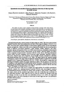
Results and discussion Acquired infrared images during the experiment were analyzed in order to detect notches in the specimens. Exemplary infrared images after 10 seconds of observation of a healthy specimen and specimens with notches on various distances from the holder were presented in fig.2. The notches in the first three cases, whose distances from the holder are 2.5, 5 and 10 mm (fig. 2b – d) were clearly detectable in infrared images. In the last case (fig. 2f), where three notches
Fig. 2. Infrared images of specimens subjected to the self-heating effect after 10 s after excitation: healthy (a), notched at the distance from a holder of 2,5 mm (b), 5 mm (c), 10 mm (d), 20 mm (e) and with multiple notches at the distance of 5, 10 and 15 mm (f)
Fig. 1. Experimental setup
through the analog output of the multi-channel signal acquisition module and drive a shaker amplifier. In order to control loading parameters force and vibration speed measurements were carried out continuously by a force sensor and laser Doppler vibrometer, respectively. The LabView® application controlled the excitation signal in feedback loop. Temperature measurements were carried out on the surface of specimens by the infrared camera with a frame ROK WYD. LXXII 앫 ZESZYT 5/2013
were presented only the notches at distances of 5 and 10 mm were detectable, while a notch at the distance of 15 mm is not visible. In the case of a specimen notched at the distance of 20 mm (fig. 2e) the damage was undetectable. The detectibility of damages depended on several parameters. Analyzing a physical nature of the selfheating effect it could be stated that the temperature distribution on the surface of a specimen and its evolution depends proportionally of stress distribution [4]. When the damage occurred in the stress field with the highest values the changes in temperature distribution were detectable. Moreover, according to slightly lower stiffness in the area of a notch the stress concentration in this area occurs, which cause changes in temperature front (see e.g. fig. 2b – d). In the presented method it is important to choose appropriate heating-up temperature. The heat 33
Fig. 3. Selection of temperature profiles (a) and longitudinal temperature profiles of investigated cases with marked positions of notches (b) – (g)
generated in composite structures during occurrence of the self-heating effect always cause irreversible structural changes. It should be noted, that the self-heating temperature evolution characteristics have some specific points, e.g. glass-transition temperature and critical self-heating temperature [6]. The glass-transition temperature determines a phase transition from the glassy state to the rubbery state of a polymer, while the critical self-heating temperature (usually a half of glass-transition temperature) determines the initiation of fatigue cracks in the structure. Previous studies show, that if the critical temperature was not exceeded the polymeric composite changes molecular structure during the loading-unloading procedure. It is result of increasing degree of cross-linking of polymeric matrix. As the self-heating temperature increased the molecular structure of a polymeric matrix is reorganized to the three-dimensional one, which results in occurrence of additional connections and hardening of a composite. The temperature increase from room temperature to 30°C does not significantly influence the structural properties, i.e. the storage modulus of the structure does not drop much, which was conducted by a dynamic thermomechanical analysis [7]. An optimal temperature of heating-up of approximately 6°C was determined empirically. Such heating-up temperature provides the best conditions for damage detection. When the temperature exceeds 30 – 35°C the damages becomes less clear in the infrared images. Additional important settings of the analysis are appropriate parameters of excitation. If the excitation force and frequency are low the self-heating effect may not occur, whereas the excitation parameters are too high so that the structure could be damaged during the analysis. It was empirically determined that the maximal stress invoked by excitation should not be higher than 40% of critical stress, which cause a breakdown of the structure. In order to improve damage detection a procedure using the presented method of the longitudinal temperature profiles of a surface of specimens should be taken into consideration. The self-heating effect 34
reveals smooth temperature distribution along the specimen, thus every imperfection or damage will be visualized as singularity on a profile. The temperature profiles for investigated cases with marked damage positions were presented in fig. 3. The profiles were determined for a middle width of specimens, which was shown in fig. 3a.
Conclusions The application of the proposed method directly depends on the stress field occurring during the excitation. Therefore, the method is limited to the cases when relatively high stress fields occur. However, a lot of engineering constructions and elements made of polymeric composites are subjected to the high stress fields and the method could be used e.g. for detection of fatigue damages. Moreover, the presented method ensures a quick damage detection and location without the necessity of using additional heat source for thermal excitation of a structure. REFERENCES 1. Mackiewicz S., Góra G.: Ultradêwi´kowe badania konstrukcji kompozytowych w przemyÊle lotniczym. XI Seminarium „Nieniszczàce badania materia∏ów”, Zakopane 2005. 2. Diamanti K., Soutis C.: Structural health monitoring techniques for aircraft composite structures, Progress in Aerospace Sciences, 46, 2010, pp. 342 – 352. 3. Dattoma V., Marcuccio R., Pappalettere C., Smith G.M.: Thermographic investigation of sandwich structure made of composite material, NTD&E International, 34, 2001, pp. 515 – 520. 4. Katunin A.: Analytical model of the self-heating effect in polymeric laminated rectangular plates during bending harmonic loading. Eksploatacja i Niezawodnosc – Maintenance and Reliability, 4(48), 2010, ss. 91 –101. 5. Katunin A., Moczulski W.: Evaluation of self-activating temperature influence on cracks initiation in GRP laminates. PAMM, 9(1), 2009, pp. 403 – 404. 6. Katunin A., Fidali M.: Fatigue and thermal failure of polymeric composites subjected to cyclic loading. Advanced Composites Letters, 21(3), 2012, pp. 64 – 69. 7. Katunin A., Gnatowski A.: Influence of heating rate on evolution of dynamic properties of polymeric laminates. Plastics Rubber and Composites, 41(6), 2012, pp. 233 – 239.
ROK WYD. LXXII 앫 ZESZYT 5/2013