Nov 16, 2010 - Subject to any disclaimer the term of this. International ... ronment determines whether a cryptographic signature on a. (52) US' ... e erences 1 e.
US008607040B2
(12) United States Patent Zimmer et al. (54)
METHOD OF PROVISIONING FIRMWARE IN AN OPERATING SYSTEM (OS) ABSENT
2009/0132839 A1 2009/0150660 A1 2011/0154065 A1*
SERVICES ENVIRONMENT
(75)
WO W0
Rothman et a1. ............ .. 713/300
5/2012 7/2012
International Search Report and Written Opinion received for PCT
(73) Assigneez Intel Corporation’ Santa Clara’ CA
§gtle2nt9Appl1cat1on No. PCT/US2011/059615, mailed on May 18, ,
(21) (22)
6/2011
OTHER PUBLICATIONS
Tang’ Shangh2“ (CN)
'
5/2009 Rothman et a1. 6/2009 Yao et a1.
2012/067882 A2 2012/067gg2 A3
(US); Rahul Khanna, Portland, OR (US); Yu Fu Li, Shanghai (CN); Di
Notice
Dec. 10, 2013
FOREIGN PATENT DOCUMENTS
Inventors: Vincent J. Zimmer, Federal Way, WA (Us); Abdul M- Bailey> Tigard’ OR (US); James W. Edwards, Portland, OR
(*)
US 8,607,040 B2
(10) Patent N0.: (45) Date of Patent:
pages.
(Us) Subject to any disclaimer the term of this ’ patent is extended or adjusted under 35
PCT International Preliminary Report on Patentability received for International Application No. PCT/U S201 1/ 059615, mailed May 30, 2013, 6 . pages
U.S.C. 154(1)) by 199 days.
>I< Cited by examiner
Appl' N05 12/947’485 Filed NOV 16 2010 .
.
(65)
Primary Examiner * Mohammed Rehman (74) Attorney, Agent, or Firm * Barnes & Thornburg LLP
,
Prior Publication Data
(57)
ABSTRACT
Methods and apparatuses for re-instantiating a ?rmware envi US 2012/0124357 A1
51
May 17’ 2012
ronment that includes one or more ?rmware functions avail
I t Cl
able at pre-boot time when transitioning the computing
( ) Gnot'sF /00
(2006 01)
G0 6F 15/1 77
device from a ?rst, higher power consumption state to a
(2006'01)
second, lower power consumption state. The ?rmware envi
'
(52)
ronment determines whether a cryptographic signature on a
US‘ Cl‘
?rmware volume is veri?ed; whether hardware resources of
~ ~ ~ ~ ~ ~ ~ ~ ~ ~ .I- ~ ~ ~ ~ ~ ~ --. ~ ~ ~ ~ ~ ~ ~ ~ ~ ~ ~ ~ ~ ~ ~ ~ ~ ~ ~ ~ ~ ~ ~ ~ ~ ~ ~ ~ ~ ~ ~ ~ ~ ~ ~ ~ ~ ~ ~ ~ .
(58)
Fleld of Classl?catlon Search USPC
volume are available; and whether aa ?rmware module of the
.... ..' ............................................ ..: ..... .. 713/2
?nnware Volume is Compatible With installed ?rmware Ofthe
See apphcanon ?le for Complete Search hlstory(56)
R f
e erences
?rmware environment. If so, the ?rmware environment
Ct d
reserves space in a memory to accommodate resources used
1 e
by the ?rmware module, and executes the ?rmware module with the computing device in the second, lower power con sumption state.
U.S. PATENT DOCUMENTS 2006/0107111 A1* 2006/0136756 A1
5/2006
Michaelis et al.
............ .. 714/15
20 Claims, 8 Drawing Sheets
6/2006 Rothman et a1.
COMPUTING PLATFORM EVOLUTION
TIME
LOW POWER CONSUMPTION STATE 111
113
PRE-BOOT TIME 08 BOOT FIRMWARE INIT
RESERVE
115
117
/
/
OS RUNNING
119
121
/
/
lF WAKE EVENT TO BE HANDLED
WAKE EVENT RECEIVED WHICH
SLEEP MODE BY FIRMWARE, WAS NOT HANDLED (E6. 83) DO NOT PROCEED BY FIRMWARE. DISK TO WAKE. SPIN UP, MONITOR CONTINUE WAKE-UP, ETC. SLEEPING
MONITOR
PORTION
MANNER
OF MEMORY
IN WHICH COMPONENTS ARE PUT TO
SLEEP
US. Patent
Dec. 10, 2013
Sheet 1 of8
US 8,607,040 B2
a?
a:
N:
r:
N:
US. Patent
Dec. 10, 2013
Sheet 2 of8
US 8,607,040 B2
201
/
228
SYSTEM POWER ON 203
CAN EVENT B HANDLED BY
/
FIRMWARE?
INITALIZE PLATFORM
232
/ 204
WAKE HARDWARE DEVICE AND/OR LAUNCH SOFTWARE FOR USE IN HANDLING EVENT
SLEEP ENABLED ACTIVITY IS ENABLED?
NO
/235 USE CACHED DEVICE I/O'S, PUT DEVICE BACK INTO D3 STATE, IF NECESSARY, AND WRITE COMMAND TO PORT TO CAUSE S3 TO OCCUR
WAKING UP DUE TO NETWORK WAKE EVENT?
208
230
/
/
CACHE IMAGES THAT MAY BE NEEDED FOR 83 CODE PATH
r
RESUME THROUGH NORMAL s3 CODE PATH
210
/ RESERVE A PORTION OF MEMORY TO SERVE AS A MAILBOX BETWEEN THE OS
AND THE FIRMWARE
Figure 2A
212 / : CONTINUE NORMAL
BOOT PROCESS
a
US. Patent
Dec. 10, 2013
Sheet 3 of8
US 8,607,040 B2
214
/
@— INSTALL FILTER DRIVER 216
II / CONTINUE OS OPERATIONS
IS SYSTEM ENTERING SLEEP? 220
/ OS NOTIFIES DRIVERS THAT SYSTEM IS ENTERING SLEEP MODE 222
I
/
FILTER DRIVER RECEIVES NOTIFICATION AND BEGINS MONITORING HOW HARDWARE DEVICES ARE PUT TO SLEEP
224
I
/
FILTER DRIvER SAvES
DATA TO MAILBOX
226
I / OS COMPLETES PUTTING SYSTEM TO SLEEP. SYSTEM IS NOW IN SLEEP MODE
.
Figure 2B
US. Patent
Dec. 10, 2013
Sheet 4 of8
US 8,607,040 B2
US. Patent
Dec. 10, 2013
Sheet 5 0f 8
US 8,607,040 B2
403
4/01
/
CHIPSET
409
PROCESSOR(S) SW/BIOS INTERFACE 460
/ HARDWARE
DEVICE s
( )
420
4/30
410
NON-VOLATILE
/
STORAGE
MEMORY
433
430
422
BIOS /
/
OS
DEVICE
DR|VER(S) 435
MAILBOX 475 415
/
/
INTERNET/NETWORK
COMMUNICATIONS
INTERFACE
482
/
sERvER(s)
400
Figure 4
U.S. Patent
Dec. 10, 2013
Sheet 6 of8
US 8,607,040 B2
US. Patent
Dec. 10, 2013
US 8,607,040 B2
Sheet 7 0f 8
600 FIRMWARE VOLUME
602
FIRMWARE MODULES
604
MANIFEST 606
SIGNATURE 608
FIRMWARE VOLUME HEADER
Figure 6
US. Patent
Dec. 10, 2013
Sheet 8 of8
US 8,607,040 B2
700 SIGNATURE VERIFIES USING
PUBLIC VERIFICATION KEY? YES RESOURCES AVAILABLE?
/702
YES FIRMWARE MODULES COMPATIBLE?
YES
706 I / RESERVE MEMORY SPACE 708 1
SET S3 DXE ENABLE FLAG TO TRUE 710 r
CREATE SYSTEM TABLE ENTRY WITH STATUS STRUCTURE
YES
II
S3 DXE ENABLE FLAG EQUALS TRUE?
SUCCESS
FAILURE
Figure 7
US 8,607,040 B2 1
2
METHOD OF PROVISIONING FIRMWARE IN
FIG. 5 is a diagram of a software stack over hardware
components according to various embodiments;
AN OPERATING SYSTEM (OS) ABSENT SERVICES ENVIRONMENT
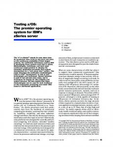
FIG. 6 is a diagram of a ?rmware volume according to an
embodiment of the present invention; and FIG. 7 is a ?ow diagram of a provisioning process accord
TECHNICAL FIELD
ing to various embodiments. This disclosure relates generally to management of com DETAILED DESCRIPTION
puting devices, and more speci?cally, to provisioning ?rm ware in a ?rmware environment of a computing device, inde
Illustrative embodiments of the present invention include,
pendent of an operating system of the computing device,
but are not limited to, methods and apparatuses for provision
while the computing device remains in a low power consump
ing ?rmware modules in a ?rmware environment of a com
tion state.
puting device, independent of the operating system of the computing device, when the computing device remains in a
BACKGROUND
low power consumption sleep mode. Various aspects of the illustrative embodiments will be
Various mechanisms exist for reducing power consump tion of computing devices. Standard technology for power management is speci?ed in Advanced Con?guration and
described using terms commonly employed by those skilled in the art to convey the substance of their work to others skilled in the art. However, it will be apparent to those skilled
Power Interface (ACPI) version 4.0, which may be found on
have been replaced with dashes to avoid unintentional hyper
in the art that alternate embodiments may be practiced with only some of the described aspects. For purposes of explana
links in this document). ACPI is a standard that most com
tion, speci?c numbers, materials, and con?gurations are set
puter systems currently use for power management and describes how a computing system looks to the operating system (OS). Power management capabilities enable a com puting device, both at component and system level, to transi tion its operating state between a higher power consumption
forth in order to provide a thorough understanding of the
the public Internet at URL www-acpi-info (note that periods
20
25
without the speci?c details. In other instances, well-known features are omitted or simpli?ed in order not to obscure the
illustrative embodiments.
state and a lower power consumption state. These modes of
Further, various operations will be described as multiple
operation are often respectively called wake and sleep states or modes. The ACPI Speci?cation de?nes seven states which
illustrative embodiments. However, it will be apparent to one skilled in the art that alternate embodiments may be practiced
30
discrete operations, in turn, in a manner that is most helpful in
understanding the illustrative embodiments; however, the
a computing device may typically be in. For example, state S3
(“S3”), may be typically referred to as standby, sleep (also
order of description should not be construed as to imply that
referred to herein as “sleep mode”), or suspend to RAM. State S5 (“S5”) may be referred to as shutdown or “of .”
these operations are necessarily order dependent. In particu lar, these operations need not be performed in the order of
A number of events may cause a computing device to
35
transition between sleep mode and wake mode i.e., wake up or go to sleep. For instance, a sleep event, which triggers a computing device to transition to sleep, might include user inactivity or user selection. When a computing device transi
tions to sleep, many of the computing device components (e. g., main processor such as central processing unit (CPU),
40
volatile memory, disk drives for mass storage, and so forth)
may also go to sleep. Once asleep, a computing device may wake upon occurrence of a wake event. A wake event may
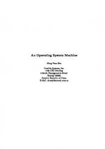
presentation. The phrase “in one embodiment” is used repeat edly. The phrase generally does not refer to the same embodi ment; however, it may. The terms “comprising,” “having,” and “including” are synonymous, unless the context dictates otherwise. FIG. 1 is a timeline illustrating a transition of a computing device from a wake mode to a sleep mode, in accordance with various embodiments. As described herein, in various embodiments, the ?rmware of a computing device may be enabled to accomplish work while the computing device is in
input from a mouse or keyboard, an e-mail message, or a
sleep mode. The ?rmware can accomplish this work indepen dently of the operating system, which results in increased
query from a remote system administrator. After a wake event is handled, and before the OS runs
for the computing device. In embodiments, the computing
include, for example, a receiving by the computing device of
again, there is an opportunity for the ?rmware of the comput ing device to perform useful work without OS involvement.
45
functionality as well as reduced overall power consumption device or system may be a desktop computer, laptop com 50
puter, mobile computing device, network server, thin client,
55
embodiments, the ?rmware may be legacy basic input/output system (BIOS), Uni?ed Extensible Firmware Interface (e.g. UEFI Speci?cation Version 2.0, 2006) compatible, Exten sible Firmware Interface (EFI) compatible (e.g., EFI Speci
or other computing device con?gured to utiliZe ?rmware. In BRIEF DESCRIPTION OF THE DRAWINGS
Embodiments of the present invention will be described by way of exemplary embodiments, but not limitations, illus trated in the accompanying drawings in which like references denote similar elements, and in which:
?cation Version 1.10, 2004) or other ?rmware. Note that EFI is a public industry speci?cation that describes an abstract
FIG. 1 is a timeline illustrating a transition of a computing device from a wake mode to a sleep mode, according to
various embodiments; FIG. 2 is a ?ow diagram illustrating an exemplary method for handling by a ?rmware a wake event independent of an
operating system (OS), according to various embodiments; FIG. 3 is a block diagram illustrating a boot and wake cycle
in a computing device, according to various embodiments; FIG. 4 is a block diagram illustrating an exemplary com
puting device, according to various embodiments;
60
programmatic interface between computing device ?rmware and operating system or other application environments. For example, EFI enables ?rmware, in the form of ?rmware mod ules, to be loaded from a variety of different resources, includ
ing ?ash memory devices, option ROMs (Read-Only Memory), various persistent storage devices (e. g., hard disks, CD-ROM (Compact Disk-Read Only Memory), etc.), or 65 from one or more computer systems over a computer net
work. More information about the Uni?ed EFI (UEFI) archi tecture may be found on the public Internet at www-ue?-org
US 8,607,040 B2 3
4
(note that periods have been replaced with dashes to avoid unintentional hyperlinks in this document). Thus, as described herein, in various embodiments, upon the transition more ?rmware functions available at pre-boot time. In
plete a task associated with the wake event. Additionally, after completion of handling of the event, the ?rmware may return the hardware component to sleep mode which includes the second lower power consumption state. Note that in the embodiments, at 123, a ?rmware compo nent, such as for example, a ?lter driver, may begin to monitor
embodiments, the re-instantiated ?rmware environment may enable the ?rmware environment to perform power manage
and collect data related to a manner in which the OS transi tions the one or more hardware components to sleep mode. In
ment functions normally performed by the OS of the comput
various embodiments, the ?lter driver may save the collected data to the mailbox or portion of memory that was reserved by the ?rmware during a pre-boot time at 112. The ?rmware may independently later use the collected data to transition the one
to a sleep mode, a computing device may re-instantiate a UEFI or other ?rmware environment that includes one or
ing device. In an embodiment, the re-instantiated ?rmware environment may provide for the provisioning of new ?rm ware modules or updating of existing ?rmware modules with out the involvement of the OS. In an embodiment, the newly installed or newly updated ?rmware modules may be
or more hardware components needed to service the wake event to and or from sleep mode. In an embodiment, a wake
executed to perform operations for the computing device.
event may result in executing a ?rmware module provisioned to the computing device after shipment to the end user. Next, FIGS. 2A and 2B are ?ow diagrams illustrating an
Referring now to FIG. 1, in the embodiments shown, a
computing device may be initialiZed during a pre-boot time by a ?rmware environment (also referred to as ?rmware), at
exemplary method for handling wake events independently
111. In various embodiments and as will be discussed in more
of the OS, according to various embodiments of the disclo
detail below, during this pre-boot time, the ?rmware may
20
sure. Blocks shown in FIG. 2A, in an embodiment, may be
process at 113 . After OS or system boot, the OS may then run 25
performed by the ?rmware. Blocks shown in FIG. 2B, in an embodiment, be performed by the OS. It will be apparent to one of ordinary skill in the art that the term “performed by the ?rmware” is shorthand for a more complex computing device interaction. In a single processor system, for instance, instruc
or operate the computing device in a functional or wake mode
tion execution may be performed by a main processor, or
at 115, which includes a typically higher power consumption state associated with normal operations. The computing device may continue to operate in wake mode until 117,
?rmware” may mean that non-operating system instructions
reserve a portion of memory or mailbox from which the
?rmware may later collect data at 112. Once pre-boot initial iZation is complete, control may be transferred to an operating
system (OS) of the computing device to continue the boot
where a sleep event causes the computing device to transition
central processing unit (CPU). Note that “Performed by the are fetched from a non-volatile memory store (?rmware), 30
to sleep mode S3, which includes a lower power consumption state. As noted above, sleep events may include a variety of
35
OS. Thus, boot instructions may be typically stored in a ?rmware boot block. Furthermore, in some embodiments, the full boot block may reside remotely, and the local boot block may contain a pointer to the remote location of the full boot block. In the embodiments of FIG. 2, a computing device or system may be powered on at block 201. The computing
40
platform may be preliminarily initialiZed by the boot block ?rmware in block 203. Other portions of the ?rmware, resid ing outside of the boot block, may play a role in the prelimi
events, such as for example, user selection or user inactivity.
After some time, in various embodiments, the computing device may receive a wake event. In some embodiments, the wake event may include a network event such as an e-mail,
con?guration directive, or other network transmission. In other embodiments, the wake event may be a sensing of an
input at an input device, touching a keyboard of the comput ing device, receiving a network packet of a certain type, etc. Processing of wake events may be initiated by system man
coupled to the processor and then executed by the processor. The processor has access to the ?rmware prior to loading the
agement interrupts (SMIs), control line changes, register
nary initialiZation. Note that the boot block is typically
?ags, or other constructs. In other cases, processing of wake events may be initiated by a chipset of the computing device. Furthermore, some wake events may trigger a powering up of
memory initialization and central processor initialiZation.
responsible for early aspects of initialiZation such as early
events, as will be discussed below in relation to embodiments
Preliminary initialization may also include identifying and resetting memory, identifying devices and components coupled to the computing device, etc.
of the present disclosure, may be processed by the ?rmware while the computing device remains in sleep mode.
iZation or soon afterwards, the ?rmware may initiate a num
45
the computing device for processing by the OS. Other wake
Accordingly, in various embodiments, the ?rmware, acting
In the embodiments shown, as a part of preliminary initial 50
independently of the OS of the computing device, may deter mine whether the wake event can be handled without retum
ing the entire computing device to the ?rst higher power consumption state. If the wake event cannot be handled by the ?rmware and the OS is to handle the wake event, then disks may be spun up, the monitor may be turned on, and the computing device may be restored to full wake mode at 121. The process ?ow may then return to 115, where the OS runs
55
mode, due to a wake event (e.g., a network wake event in at
least one embodiment). In various embodiments, where the computing device is not waking up due to a network wake
event, but has simply completed powering up, the pre-boot
or operates the computing device in wake mode. If, however, the ?rmware determines that the wake event can be handled
60
independent of the OS and without returning the entire com
puting device to the ?rst higher power consumption state, the
ing the entire computing device, the ?rmware may wake one or more hardware components or devices to service or com
process may continue to a block 208. At block 208, the ?rm ware may proceed to cache images that may be needed at a
later time. For example, it may cache data needed for a sleep mode (e.g. S3). Next, at a block 210, the ?rmware may reserve, during this pre-boot time, a portion of memory in a
?rmware can cause the wake event to be handled. The com
puting device may thus continue to sleep at 119. In some embodiments, dependent on the wake event and without wak
ber of policy questions to determine a status of the computing device. At block 204, the ?rmware may determine if sleep enabled activity is enabled. If so, processing continues with block 206. If not, processing continues with block 230. In the embodiments, the ?rmware may ask at block 206, whether the computing device is waking up or transitioning out of sleep
65
tangible computer readable storage medium of the computing device. In an embodiment, the portion of memory may serve as a mailbox of the ?rmware. Note that typically, computing
US 8,607,040 B2 5
6
device resources are under control of the OS unless the ?rm Ware actively reserves such resources for itself. Furthermore,
components to sleep, e.g., those associated With a netWork
transmission received by the computing device during sleep
in various embodiments, to be discussed beloW, input/ output
mode, the ?rmWare environment is able to initiate a transition to Wake mode a plurality of additional hardWare or other
(I/O) data related to a manner in Which the OS may transition one or more hardWare components to sleep may be saved (eg
components of the computing device. In various embodi
by a monitoring component of the OS) into the mailbox to be accessed at a later time by the ?rmware. In the embodiments, enough memory may also be reserved that may alloW the ?rmWare to reinitialiZe previously cached images.
ments, the ?rmWare environment is enabled to retrieve I/O data related to a manner in Which any of a plurality of hard Ware devices is transitioned to sleep mode. Such I/ O data may be retrieved from a mailbox that Was reserved by the ?rmWare
In the embodiments shoWn, at a next block 212, the ?rm Ware may continue a normal boot process and the OS may be
during a pre-boot time. In various embodiments, the ?rmWare
given control and launched. At block 214 on FIG. 2B, the OS may install a component, such as, for example, a ?lter driver.
nents to sleep mode, a poWer management function typically
As Will be seen beloW, the ?lter driver may serve as the
Ware environment is enabled to provision neW or updated
monitoring component to collect I/ O data related to transition of the hardWare components to sleep mode. Normal OS
?rmWare modules. Referring noW to FIG. 3, embodiments may conjoin a module S3 resume architecture of, for instance, the Platform Innovation Framework for the Extensible FirmWare Interface
environment is enabled to transition the hardWare compo
only performed by the OS. In various embodiments, the ?rm
operations may continue at a block 216. At a decision block
218, if input has not been received for a certain period of time or other computing device policy dictates, the OS may tran
sition the computing device to sleep mode. If, for example the
(EFI)iDraft for RevieW, Version 0.9, Sep. 16, 2003, avail 20
policy does not dictate that the computing device transition to sleep mode, OS operations may continue at a block 216. In the
Platform InitialiZation (PI) Speci?cation, version 2.3, pub lished May 8, 2009, a full complement of PI pre-EFI (PEI)
alternative, returning to decision block 218, if the computing device is to enter sleep mode, the OS may continue doWnWard from decision block 218 to block 220. In the embodiment, the OS may then send a message notifying all or substantially all hardWare component or hardWare device drivers that the hardWare components are to transition to sleep mode. The
25
modules and PI Driver Execution Environment (DXE) driv ers may be invoked during boot from an S5 mode (“off”). As a result, a UEFI environment that may be used by pre-OS
applications, eg UEFI shell, 3rd party UEFI drivers/option ROM’s, and UEFI OS loaders, is created. During S3, hoW
?lter driver may receive or detect this noti?cation at block 222
and begin monitoring input/output (I/O) data related to a
able at WWW-intel-com/technology/frameWork (note that periods have been replaced With dashes to avoid unintentional hyperlinks). Typically, for example, according to a UEFI
30
ever, because of S3 resume time constraints, the computing
manner in Which the one or more hardWare devices or com
device may run a standard PI resume ?oW that may typically
ponents are transitioned to sleep mode, e.g. I/O signals
include only a subset of PEI Without DXE. As such, during an
betWeen a hardWare device interface and the hardWare device driver. At a block 224, the ?lter driver then may collect the I/O data and save it to the mailbox Which Was reserved by the ?rmWare environment at a pre-boot time (described at block
S3 resume mode, rich UEFI driver features may not be avail 35
210). Finally, at a block 226, the OS has completed transi
tioning the computing device to sleep mode. Note that the I/O data saved to the mailbox at block 224, as alluded to earlier, may be used at a later time to enable the ?rmWare to use the I/ O data during and/ or after the handling
40
of a Wake event. Thus, for example, returning up to decision block 206, if the computing device is Waking up due to a Wake
during a normal boot 301 after a poWer-on or reset, a pre 45
handled by the ?rmWare, independent of the OS and Without Waking or returning the entire computing device to a higher poWer consumption state. If the ansWer is NO, the computing device resumes through the normal S3 codepath at block 230 and eventually continues the normal boot process at 212. If the ansWer is YES, hoWever, the ?rmWare may cause the netWork event to be handled independently of the OS. In some embodiments, at a block 232, the ?rmWare may Wake or transition only one or more (but not all) hardWare components
OS driver pinned) pages for running UEFI boot service appli cations While the OS is in sleep mode. Referring noW to FIG. 3, shoWn in the embodiments, a block diagram 300 illustrates a boot and Wake cycle, imple mented according to a UEFI architecture. In the embodiment,
memory init security (SEC) phase 302 (“SEC 302”) may
event eg netWork Wake event, the YES arroW may be fol
loWed. At block 228, the ?rmWare may determine, While the OS remains in sleep mode, Whether the netWork event can be
able. HoWever, various embodiments of the disclosure pro vide that a computing device may implement DXE 330 dur ing S3. Thus, as shoWn in FIG. 3, S3 may include DXE to recreate a UEFI environment in some pre-OS sequestered (or
begin. SEC 302 may support security checks of an initial operating code to be executed on a computing device. Next, in the embodiment, SEC 302 may transition to a CPU/memory
init, pre-EFI (PEI) phase 304 (“PEI 304”). PEI 304 may provide, for example, a method of loading and invoking spe 50
ci?c initial (INIT) con?guration routines for a processor, chipset, and motherboard. PEI 304 may discover memory and prepare a resource map that may be handed off to a late init,
driver execution environment (DXE) phase 306 (“DXE 306”). DXE 306 may include the invoking of DXE drivers 55
responsible for initialiZing the processor, chipset, and plat form components, as Well as providing softWare abstractions for console and boot devices. As shoWn at 310, DXE 306 may save I/O controller settings as part of a boot script table in a
to a higher consumption state and/ or launch softWare for use
in handling the netWork event. At a block 235, the ?rmWare may use cached device I/Os to put the computing device back
into a D3 state, and if necessary, Write a command to the reserved memory such as a non-volatile store (NVS). A boot 60 script may include a set of actions to be replayed upon an S3 appropriate port to cause a transition to S3 to occur.
restart to bring the computing device back to a state it Was in
Thus, in various embodiments, a ?rmWare environment of a computing device is re-instantiated once a computing
before transitioning into sleep mode. Atypical boot script Will
device transitions to sleep mode. In embodiments, the ?rm Ware environment is enabled to perform poWer management or other functions normally performed by the OS of the com puting device. In some embodiments, not only does the com puting device have an ability to transition certain hardWare
restore I/O device and CPU state information. As seen at 319, in an S3 resume boot, SEC 320 may be 65
implemented. Next, at 325, S3 PEI modules may restore PEI phase con?gurations from the NVS in 310, e. g. basic restor
ing of chipset (CS), hardWare (HW), and video settings. Thus,
US 8,607,040 B2 7
8
in embodiments, updated DXE 330 may be implemented during S3, while the OS is sleeping. DXE 330 may be facili
software stack 510 which communicates with a serial
advanced transport architecture (SATA) controller 512. The SATA controller communicates with storage devices (not shown in FIG. 5). The LPUD app performs various activities
tated by several components or phases, including a S3 DXE initial program load (IPL) 335, S3 DXE core 340, S3 DXE
FirmwareVolume (FV) 345, S3 Boot Device Selection (BDS) 350, S3 Network Proxy Actions 355, and S3 DXE Terminator 360. As noted above, an instantiation of a substantially fully
in an OS-absent state; these can include a scan of the disk for
virus signatures (e.g., anti-virus client), a remote back-up of the disk contents to a computing cloud backup server (e.g., backup client), or acting as a ?le server (e. g., serving MP3s or MP4s to an In-Vehicle Infotainment PC while the laptop’s
formed UEFI interface may be implemented as a result of
including DXE 330 in S3. Typically, only a smaller number of UEFI drivers are added during a pre-boot phase. In an embodiment, however, an OS driver may add additional UEFI drivers into the UEFI environment. In various embodiments, UEFI drivers may be collected from alternate sources. In some embodiments, these additional drivers may be provi
main OS is suspended and the laptop is in the LPUD state).
sioned on a UEFI system partition or via other methods to
provides for a Socket Library to perform send and receive operations in order to support the backup (e.g., send of data from client) and anti-virus (AV) scan (e.g., receive of signa
The LPUD services API provides access to the disk in a fashion that is non-destructive to the ?le-system, such as read operations, so that when the main OS wakes up, it doesn’t ?nd the disk in a corrupted state. The LPUD service API also
enhance the number of UEFI drivers available during DXE 330.
FIG. 4 illustrates an exemplary computing device 400 in which an embodiment of the present disclosure may reside. In
various embodiments, a computing device 400 comprises
ture ?les). The User OS side may receive status information 20
not busy. Also, the User OS will provide the console for in-band activation of the LPUD application, including but not limited to, opting-in, and deciding how much memory to sequester for LPUD (since this physical memory will be lost
various elements coupled via a bus 420. As shown, the ele ments may include a processor 401, memory 410, a chipset
403, hardware device(s) 460, a non-volatile storage 430, such as ?ash memory, and communications interface 415. Chipset 403 may be endowed with the earlier described ?rmware.
Memory 410 may include OS 422, earlier described mailbox 435, and device driver(s) 480. Processor 401 may be any type of processor capable of executing software, such as a micro processor, digital signal processor, microcontroller, or the like. Though FIG. 4 shows only one such processor 401, there
from the LPUD once the main OS wakes up, or the User OS may initiate a transfer to the LPUD state when the User OS is
25
to the User OS and may have a performance impact). In an embodiment, in a ?rmware environment, EFI BIOS 514 (stored in NVS 430 as BIOS 433 in FIG. 4) includes at
least several components. New Technology File System 30
(NTFS) driver 516 communicates with hard drive 518 to read and write data. Network interface controller (NIC) driver 520
may be one or more processors in computing device 400 and
communicates with NIC 522 to read and write data over a
one or more of the processors may include multiple threads, multiple cores or the like. In various embodiments, a ?rm
network coupled to the computing device. WiFi shim 524 provides for the UEFI UNDI interface, as de?ned in Appen
ware module of the BIOS 433 may determine or collect
dix E2 of the UEFI 2.3 speci?cation, Command and Data Blocks (CDBs), that provide raw data gram reads and writes
information related to a transition of one or more hardware 35
devices 460 between a ?rst higher power consumption state and a second lower power consumption state by monitoring
to the Wireless Nic (W-NIC) in the computing platform; this
I/O signals on bus 420 communicated between a hardware
(ME) based W-NIC where the UNDI CDBs are proxied through the Host Extended Command Interface (HECI) of a
can include a third party W-NIC or a management engine
interface of one or more hardware devices 460 and device
driver(s) 480. While in sleep mode, the ?rmware may handle
40
chipset commercially available from Intel Corporation. Man
one or more network or wake events as earlier described.
ageability Engine (ME) 526 may be included to provide an
The communications interface 415 may include a network ing interface such as a network interface card (NIC) or the like. The NIC may be communicatively coupled to an Inter net/Network 475 including a remote server or server(s) 482 via, e.g., a serial over local area network (LAN) interface. The
out-of-band chipset network-facing management capability. EFI LPUD agent 528 coordinates the provisioning of new
?rmware modules and/or updating existing ?rmware mod 45
communication interface may support Transfer Control Pro
tocol/Intemet Protocol (TCP/IP), hypertext transfer protocol (HTTP) or Simple Object Access Protocol (SOAP), or other communication protocol. The NIC may use other means to
50
communicate over a network, for instance, Integrated Drive Electronics (IDE) redirection (not shown) or other means. Note that in embodiments, handling a wake event may include but is not limited to responding to particular packet
types, keeping dynamic host con?guration protocol (DHCP)
530 may be included to leverage the LibSocket and Lib C wrapper 532 may be included to abstract POSIX-like pro gramming APIs. Firmware module 534 comprises a new or updated ?rmware module that may be obtained from an ISV and installed into the computing device as disclosed herein. In an embodiment, EFI BIOS 514 also includes S3 DXE Enable
?ag 536 and public veri?cation key 538 (called Kpub_s3extension_veri?cation in one embodiment). 55
leases alive, low power background activities, such as for example, scanning memories for viruses, and remote ?le backup s/restores, and the like. In the embodiment shown, the
In an embodiment, the computing device has the EFI BIOS ?rmware and at least one S3 DX IPL ?rmware module
installed on the system board during the manufacturing pro cess at the factory. The S3 DXE Enable ?ag 536 in the EFI
chipset 403 may also include a software interface for a basic
input output system (BIOS) 409.
ules while the computing device is in a sleep state. Hyper text
transport protocol (HTTP)/HTTP secure (HTTPS) plug-in
BIOS may be set to false at manufacturing time. The com 60
puting device may then be shipped to a user. While being
FIG. 5 is a diagram of a software stack over hardware
operated by the user, the computing device may be booted
components according to various embodiments. In an
into the OS via the S4 state (hibernate) or the S5 state (full power cycle). The user, via the OS and a conventional web browser, may visit a selected website to download a S3 DXE ?rmware volume. FIG. 6 is a diagram of a S3 DXE ?rmware volume 600 according to an embodiment of the present invention. Firm
embodiment, in a user OS visible environment, a low power
update/download (LPUD) application 500 and associated LPUD services application programming interface (API) 502 may be interposed between independent software vendor (ISV) application programs 504, 506, 508, and a storage
65
US 8,607,040 B2 9
10
ware volume 600 comprises a binary ?le having a ?rmware volume header 608 and a cryptographic signature 606 that covers the contents of the ?rmware volume. Firmware vol
In an embodiment, an alternate way to supply memory for the hardware resources used is for the OS to “pin” or reserve the OS pages that the S3 DXE ?rmware module will use and
ume 600 further comprises one or more ?rmware modules
pass the (possibly scattered) page list into the UpdateCapsule
602. In an embodiment, the ?rmware modules have the “.e?” ?le extension. In an embodiment, ?rmware modules com
runtime service call. Thus, the ?rmware does not steal memory from the OS memory map, but instead will take the scattered page list from the OS and make these pages “?rm
prise drivers. Firmware modules 602 comprise ?rmware
ware reserved” thereafter and use them for launching the S3 DXE ?rmware modules. In an embodiment, the OS installer can put the S3 DXE ?rmware volume in a directory on a UEFI service partition
binary code for one or more S3 DXE IPL ?rmware modules.
In embodiments of the present invention, the ?rmware mod ules may be read from the ?rmware volume, installed in non-volatile storage 430, and executed during a low power
and pass the location of the ?rmware volume via the Update Capsule call. In another embodiment, the EFI BIOS may probe the UEFI system partition for the ?rmware volume. In either case, the EFI BIOS cryptographically veri?es the con tents of the ?rmware volume prior to copying the content into memory used in successive S3 DXE activations.
consumption state as described further herein. Firmware vol ume further comprises manifest 604. Manifest 604 declares
what computing device hardware resources (I/O devices, memory, etc.) that the S3 DXE ?rmware volume will con sume or use when executed. The S3 DXE ?rmware volume
was previously signed by a third party (such as an indepen
dent software vendor (ISV), original equipment manufacturer (OEM), or independent BIOS vendor (IBV) using a signing server
that
has
an
associated
private
key
In an embodiment, upon a successive S3 resume, if the S3 20
(Kpriv_s3extension_veri?cation). An OS-present application program may then prompt the
DXE Enable ?ag is true, then the EFI BIOS may launch the S3 DXE IPL and the associated ?rmware modules from the S3 DXE ?rmware volume prior to going back to sleep and/or
25
passing control to the OS resume vector. Thus, a one touch provisioning model where an OS-hosted installer can activate a ?rmware module download capability in a lower power consumption state has been described. This
application invokes the UpdateCapsule UEFI runtime service
capability may be activated after the computing device has
with a pointer to the S3 DXE ?rmware volume stored in non-volatile storage. Upon restart (either a warm start or the S3 state, depending on how the EFI BIOS ?rmware imple 30
been shipped to a user. This allows an entity to provide S3 DXE IPL code and the veri?cation key infrastructure to third parties as small “hooks” in the EFI BIOS, but post-ship, a ?rmware volume can be added to the computing device for
user to inquire whether the user wishes to install the S3 DXE extension ?rmware module(s). If the user does want to install
the ?rmware module, in an embodiment the OS-present
ments the UpdateCapsule runtime service, which should be opaque to the user), the EFI BIOS ?rmware detects the pres ence of the S3 DXE ?rmware volume in non-volatile storage. FIG. 7 is a ?ow diagram of a provisioning process accord ing to various embodiments. In an embodiment, this process ing may be performed while the computing device is in a S3 sleep state as shown in FIG. 3. At block 700, the EFI BIOS
purposes of executing in the OS-suspended, S3 DXE envi ronment.
The techniques described herein are not limited to any
particular hardware or software con?guration; they may ?nd 35
applicability in any computing, consumer electronics, or pro ces sing environment. The techniques may be implemented in
?rmware determines whether the cryptographic signature
hardware, software, or a combination of the two. The tech
606 on the S3 DXE ?rmware volume veri?es using the public veri?cation key (Kpub_s3extension_veri?cation). If so, at block 702 the EFI BIOS ?rmware checks to determine if the hardware resources requested by ?rmware volume manifest
niques may be implemented in programs executing on pro grammable machines such as mobile or stationary computers, 40
personal digital assistants, set top boxes, cellular telephones and pagers, consumer electronics devices (including DVD
are available. If so, at block 704, the EFI BIOS determines if the ?rmware modules in the ?rmware volume are compatible
players, personal video recorders, personal video players,
with the existing ?rmware already installed (e.g., have their
other electronic devices, that may include a processor, a stor
dependencies been satis?ed, is the correct instruction set architecture present, etc.). If so, at block 706, the EFI BIOS
satellite receivers, stereo receivers, cable TV receivers), and 45
one input device, and one or more output devices. One of
reserves a memory space in non-volatile memory large enough to support the resources to be used by the new or
updated ?rmware modules from the ?rmware volume. At block 708, the EFI BIOS sets the S3 DXE Enable ?ag to true. If at blocks 700, 702, and 704, any checks fail, processing
ordinary skill in the art may appreciate that the disclosure can 50
55
by a Vendor GUID. The EFI BIOS in this case would create such a table that has a BOOLEAN value which is “TRUE” for success and “FALSE” for failure. The system table entry comprises a status structure for returning a status value relat
Program instructions may be used to cause a general-pur
60
Enable ?ag is true, a success status may be returned at block
65
failure status may be returned at block 716.
a communications network.
pose or special-purpose processing system that is pro grammed with the instructions to perform some the opera tions described herein. Alternatively, the operations may be
ing to execution of the ?rmware module to the OS in response to the UpdateCapsule runtime service call. This is done after leaving S3 and waking up the system, in order to pass status information from the embedded S3 processing environment back into the main host OS. At block 712, if the S3 DXE
714, and the ?rmware module may be executed. Otherwise, a
be practiced with various system con?gurations, including multiprocessor systems, minicomputers, mainframe comput ers, independent consumer electronics devices, and the like. The invention can also be practiced in distributed computing environments where tasks or portions thereof may be per formed by remote processing devices that are linked through
continues at block 710. At block 710, the EFI BIOS creates a
system table entry. The system table has a EFI Con?guration Table, as described in section 4.6 of the UEFI 2.3 speci?ca tion. It allows for installing a series of additional tables named
age medium accessible by the processor (including volatile and non-volatile memory and/or storage elements), at least
performed by speci?c hardware components that contain hardwired logic for performing the operations, or by any combination of programmed computer components and cus tom hardware components. The methods described herein may be provided as a computer program product that may include a machine accessible medium having stored thereon instructions that may be used to program a processing system or other electronic device to perform the methods. The term
US 8,607,040 B2 11
12
“computer readable medium” used herein shall include any medium that is capable of storing or encoding a sequence of instructions for execution by a computing device and that
value relating execution of the at least one ?rmware module to
the operating system of the computing device. 8. A computing device comprising:
cause the computing device to perform any one of the meth ods described herein. The term “computer readable medium” shall accordingly include, but not be limited to, solid-state
a processor;
a ?rmware environment con?gured to be operated by the processor; wherein the ?rmware environment includes a plurality of ?rmware functions employed to boot the apparatus into an operational state consuming a ?rst power level;
memories, and optical and magnetic disks. Furthermore, it is common in the art to speak of software, in one form or another
(e.g., program, procedure, process, application, module, logic, and so on) as taking an action or causing a result. Such expressions are merely a shorthand way of stating the execu tion of the software by a processing system cause the proces
wherein the processor downloads a ?rmware volume
sor to perform an action or produce a result.
state, the ?rmware volume comprising a manifest declaring hardware resources of the computing device to be used, during a second power level lower than the ?rst power level, by the at least one ?rmware module; wherein the ?rmware environment is further con?gured to
including at least one ?rmware module to the computing
device when the computing device is in the operational
What is claimed is: 1. A method for provisioning a ?rmware module to a com
puting device, the method comprising: downloading a ?rmware volume including at least one ?rmware module to the computing device when the
be re-instantiated to include at least a subset of the ?rm
computing device is in a ?rst, higher power consumption state, the ?rmware volume comprising a manifest declaring hardware resources of the computing device to be used during a second, lower power consumption state by the at least one ?rmware module; re-instantiating a ?rmware environment that includes one or more ?rmware functions available at pre-boot time,
when transitioning the computing device from the ?rst, higher power consumption state to the second, lower power consumption state; determining, by the ?rmware environment, whether a cryp tographic signature on the ?rmware volume is veri?ed; determining, by the ?rmware environment, whether the hardware resources of the computing device requested
ware functions employed to boot the apparatus when the apparatus transitions from the operational state to a sleep state consuming the second power level, to enable the ?rmware environment to
20
25
determine, by the ?rmware environment, whether a cryp tographic signature on the ?rmware volume is veri?ed; determine, by the ?rmware environment, whether the hard ware resources of the computing device requested by the manifest of the ?rmware volume are available;
determine, by the ?rmware environment, whether the at least one ?rmware module of the ?rmware volume is
compatible with installed ?rmware of the ?rmware envi ronment;
30
reserve space in a memory to accommodate resources used
by the manifest of the ?rmware volume are available;
by the at least one ?rmware module; and
determining, by the ?rmware environment, whether the at least one ?rmware module of the ?rmware volume is
execute the at least one ?rmware module with the comput
ing device in the second, lower power consumption
35
compatible with installed ?rmware of the ?rmware envi ronment;
state.
9. The computing device of claim 8, wherein the ?rmware volume comprises a header, a cryptographic signature cover
reserving space in a memory to accommodate resources
used by the at least one ?rmware module; and
puting device in the second, lower power consumption
ing the contents of the ?rmware volume, and the at least one ?rmware module. 10. The computing device of claim 9, wherein the at least
state.
one ?rmware module comprises binary code for one or more
executing the at least one ?rmware module with the com
40
2. The method of claim 1, wherein the ?rmware volume
EFI S3 DXE IPL ?rmware drivers.
comprises a header, a cryptographic signature covering the contents of the ?rmware volume, and the at least one ?rmware module. 3. The method of claim 2, where the at least one ?rmware module comprises binary code for one or more EFI S3 DXE IPL ?rmware drivers.
4. The method of claim 3, wherein the ?rmware environ
11. The computing device of claim 10, wherein the ?rm 45
ware environment comprises a S3 DXE IPL enable ?ag set to
false at manufacturing time of the computing device, and wherein the ?rmware environment sets the S3 DXE IPL
enable ?ag to true when the cryptographic signature is veri ?ed, the hardware resources are available, and the at least one 50
?rmware module is compatible. 12. The computing device of claim 11, wherein upon a successive S3 resume, if the S3 DXE IPL enable ?ag is true, the ?rmware environment launches the S3 DXE IPL and associated ?rmware modules from the ?rmware volume prior
ment comprises a S3 DXE IPL enable ?ag set to false at
manufacturing time of the computing device, and further comprising setting the S3 DXE IPL enable ?ag to true when
the cryptographic signature is veri?ed, the hardware
resources are available, and the at least one ?rmware module 55 to passing control to an operating system resume vector.
is compatible. 5. The method of claim 4, further comprising, upon a successive S3 resume, if the S3 DXE IPL enable ?ag is true, launching the S3 DXE IPL and associated ?rmware modules from the ?rmware volume prior to passing control to an operating system resume vector. 6. The method of claim 1, wherein the ?rmware volume is
13. The computing device of claim 8, wherein the ?rmware volume is provided and signed by a party other than the manufacturer of the computing device, and the ?rmware vol ume is installed to the computing device after shipment to a 60 user.
14. The computing device of claim 8, wherein the ?rmware environment creates a system table entry with a status struc
provided and signed by a party other than the manufacturer of the computing device, and the ?rmware volume is installed to
ture for returning a status value relating execution of the at least one ?rmware module to the operating system of the
7. The method of claim 1, further comprising creating a
computing device. 15. A non-transitory, computer-readable medium compris
system table entry with a status structure for returning a status
ing one or more instructions that when executed on a proces
the computing device after shipment to a user.
65
US 8,607,040 B2 13
14
sor of a computing device perform one or more operations to
16. The computer-readable medium of claim 15, wherein the ?rmware volume comprises a header, a cryptographic signature covering the contents of the ?rmware volume, and
provision a ?rmware module to the computing device by re-instantiating a ?rmware environment that includes one or more ?rmware functions available at pre-boot time,
the at least one ?rmware module.
when transitioning the computing device from a ?rst, higher power consumption state to a second, lower power consumption state;
17. The computer-readable medium of claim 16, where the at least one ?rmware module comprises binary code for one or more EFI S3 DXE IPL ?rmware drivers.
downloading a ?rmware volume including at least one ?rmware module to the computing device when the
18. The computer-readable medium of claim 17, wherein
computing device is in the ?rst, higher power consump
the ?rmware environment comprises a S3 DXE IPL enable
tion state, the ?rmware volume comprising a manifest declaring hardware resources of the computing device to
?ag set to false at manufacturing time of the computing device, and further comprising instructions to set the S3 DXE IPL enable ?ag to true when the cryptographic signature is
be used during the second, lower power consumption state by the at least one ?rmware module;
veri?ed, the hardware resources are available, and the at least one ?rmware module is compatible.
determining, by the ?rmware environment, whether a cryp tographic signature on the ?rmware volume is veri?ed;
determining, by the ?rmware environment, whether the
19. The computer-readable medium of claim 18, further
hardware resources of the computing device requested by the manifest of the ?rmware volume are available; determining, by the ?rmware environment, whether the at
comprising instructions to, upon a successive S3 resume, if the S3 DXE IPL enable ?ag is true, launch the S3 DXE IPL and associated ?rmware modules from the ?rmware volume prior to passing control to an operating system resume vector.
least one ?rmware module of the ?rmware volume is
20
compatible with installed ?rmware of the ?rmware envi ronment;
20. The computer-readable medium of claim 15, further
reserving space in a memory to accommodate resources
used by the at least one ?rmware module; and executing the at least one ?rmware module with the com
puting device in the second, lower power consumption state.
25
comprising instructions to create a system table entry with a status structure for returning a status value relating execution of the at least one ?rmware module to the operating system of
the computing device. *
*
*
*
*