Introduction. Construction of the transport pipeline is always very costly. Therefore all stages of its building (beginning with a project, and finishing with the tests ...
VOLUME 1,
Journal of Automation, Mobile Robotics & Intelligent Systems
N° 3
September 2007
METHODS AND SYSTEMS OF LEAK DETECTION IN LONG RANGE PIPELINES Received 6th June; accepted 10th July.
Mateusz Turkowski, Andrzej Bratek, Marcin Słowikowski
Abstract: No matter how carefully the pipeline is designed and built, there is always a probability of leaks. Pipeline leak detection systems play therefore a key role in minimization of the occurrence of leaks probability and their impacts. As the vast assortment of technologies is available today, the paper provides the background information to facilitate the choice of leak-detection system. The paper deals with external methods based on external measurements and with some internal methods based on flow and pressure measurements in the pipeline: pressure wave detection and volume balance method; then gradient and analytical methods were described. Additionally, the discussion of error sources and final conclusions are presented. Keywords: leak detection, leak localization, integrity of pipelines, transport pipelines, pipelines safety
1. Introduction Construction of the transport pipeline is always very costly. Therefore all stages of its building (beginning with a project, and finishing with the tests and commissioning) and operating must fulfill the regulations and recommendations of numerous standards and regulations [1], which purpose is to provide long-lasting operation of pipeline system. The damages may be caused by corrosion or erosion (Fig. 1) of external and internal walls, inhomogeneity or crack of the welds, indentation of the walls and material defects. Counteraction may consist in installing cathodic protection systems (earlier passive, but nowadays predominantly active, under surveillance of the telemetry system).
Fig. 1. Numerical visualization of the leak caused by erosion [2].
Fig. 2. Consequences of inattentive diggings [3]. Degradation of the pipeline material may occur as a result of stresses alterations that are caused by changes of the pressure and the deformations of the pipeline caused by the soil dislocations, which lead to the fatigue and forming of the micro-gaps. During operation periodical inspections of the pipeline condition are carried out with the use of so-called intelligent pistons, it enables to detect and localize damages or leaks at a very early stage of development. Despite of that the occurrence of leaks is rather inevitable. They are caused by oversight or by underestimating progress of the specific defects during the tests. However, considerably more often damages are caused by people operations: accidental - careless diggings (Fig. 2), building or repair works in the proximity of the pipeline, or conscious - i.e. illegal stealing of the transported media. Also possible terrorist attacks cannot be neglected. The leak brings always large and various losses: suspending of the product or material transport, the cost of the damage reparation and loss of transported product. In case of explosive or/and flammable or/and dangerous to environment media (e.g. petroleum and other oil products), the leak causes hazard for safety of the people and the equipment (including the pumping installation), as well as an environmental contamination. Events like that induce high social and financial costs, which are proportional to the intensity and duration of the leak. The recultivation costs of the polluted ground may reach several millions euro. If a leak happened, then its effects can be minimized only by extremely fast detection and localization of the leak point and quick dispatcher reaction (stopping pumArticles
39
VOLUME 1,
Journal of Automation, Mobile Robotics & Intelligent Systems
ping, closing the valves, organizing provisional damage repair etc.) Damages of pipelines transporting natural gas are not neutral for environment as well. Methane, the main component of natural gas - is one of the greenhouse gases. Moreover, natural gas mixed with atmospheric air in amount 4-15% becomes very sensitive for sparkling or flame, causing an explosion of this mixture - as is shown in the Fig. 3.
N° 3
September 2007
The flow rate in liquid pipelines is usually constant, close to the nominal flow rate, limited by pumps efficiency and by pressure drop along the pipeline. In gas pipelines the flow rate is a function of gas demand, on which gas supplier does not have much influence. Gas demand is variable during twenty-four hours cycle (rising within a day) and during the year (rising within low temperature periods). Table 1. The influence of various factors on pipeline behavior and leak detection systems in liquids and gas pipelines.
Fig. 3. Burning pipeline a water curtain is applied. Photo by M. Turkowski. Particularly dangerous leaks of a gas pipeline happen in the winter. Under frozen crust of the earth gas may penetrate in long distance, and an explosion may happen in quite unexpected places. That is why for over 30 years research in the domain of leak detection and localization systems is carried out all over the world. Leak detection problems in single segments of pipeline in the steady state are generally solved. Up to now, however, a universal reliable system, which can work in every operating condition, for every pipeline system and during transients does not exist. Therefore, the issue of leak detection will be probably topical for a long time. Complications came from fact that individual pipelines differ from each other, and in each case one has to place special emphasis on totally different circumstances, which are crucial for given detection system. The examples of such differences between gas and liquid pipelines are presented in table 1. Configuration of liquid pipeline is usually quite simple - most often we have a single pipeline, starting at the supplier and ending at the recipient of medium, the branches are rather rare. A uniform gasification of an area requires however much more complicated configurations. It is clearly shown on the maps at the websites of gas and liquid pipelines operators [4, 5]. The inertia of a fluid has not great influence on the gas pipelines because of the low gas density (unless sudden and big changes of demand or very high pressures and diameters of the pipe), whereas the inertia can never be omitted in case of liquid pipelines. The medium compressibility has great influence in the case of gas pipelines and it is less important for liquid pipelines. Liquid compressibility joined with elastic deformations of pipeline lead however to sustained (tens of minutes) transient states after technological operations (start of pumping, valves operations), which may cause a water hammer phenomenon. Compressibility is less significant for stationary flows. 40
Articles
Nr
Criterion
Liquid
Gas
1
complication level of the pipeline system
not large
large (except wide-ranging transit-pipelines)
2
inertia of liquid
large
small
3
compressibility of medium
small
large
4
elastic deformations of the pipeline caused by changes of pressure
large
small
5
variability of flow
steady, near to nominal (except the transient states)
various between day and night and depending on the season
6
continuity of work
interrupted flow
constant flow
7
presence of the second phase
large influence
small influence
Liquid pipeline can be switched on and off periodically, depending on contracts between the supplier and the recipient. On the contrary, a gas pipeline once started should be operated continuously for all operating time (often for several dozen years), excepting possible failures. Presence of gas inclusions in liquid have a fundamental effect on liquid compressibility (1% of gas inclusions in form of uniformly spaced tiny bubbles can multiply compressibility of such mixture even several hundreds times), whereas similar content of liquid aerosol in gas may be neglected from the point of view of detection system. The table 1 refers also to plant technological pipelines, they are however much shorter than long-range transport pipelines, and because of that the influence of some factors may be omitted.
VOLUME 1,
Journal of Automation, Mobile Robotics & Intelligent Systems
2. Tasks and general classification of the leak detection and localization methods Detection of the gas pipelines leaks system should comply three following tasks: Leak detection. Alarm generation. Leak localization. Estimation of the flow rate of leaking medium. Very important factor, which decides on usefulness of the method and detection algorithm, equivalent to sensibility for real damages, is also resistance to disturbances. That means non-generation of false alarms, i.e. caused by technological operation (starting/stopping compressor/ pump, change of supply tank, change of the type of transported medium, closing/opening valves, changing receiving tanks). The methods of leak detection may be divided into two general categories [6, 7]: Direct (external) - the detection is done from outside the pipe through application of specialized sensors or visual observation. Indirect (analytical, internal) - the detection is based on measurements and analysis of flow parameters (mainly pressure and fluid flow rate/velocity, sometimes temperature and density). Indirect methods may be divided into three categories: Based on detection of the acoustic wave caused by the leak. Based on mass balance concept, taking into consideration accumulation. Analytical - based on mathematical model and measurement of an object acquired from telemetry or SCADA system - these methods consist in pipeline modeling in real time, and continuous comparison of the model with the object.
N° 3
September 2007
(Fig. 4). One of them is a continuity circuit monitoring condition of the cable (checking possible physical damages). The second one - the alarm circuit - is a normally open circuit, shorting only in the case of a leak. There is a possibility to use various mechanisms. If transported medium is conductive, the short happens naturally, because the conductive liquid facilitates current flow between the cables. For hydrocarbons a special polymer is used as insulation. The polymer degrades in the presence of the hydrocarbons allowing the cables to touch. Measurement of voltage drops in the circuits enables to pinpoint the position of the leak. continuity circuit
UZ
continuity circuit
UZ
alarm circuit
Alarm
no leak
Alarm
alarm circuit
with leak
short circuit induced by leak
Fig. 4. Cable leak sensor. A concentric cable with a hydrocarbons permeable insulation can also be used. If hydrocarbons penetrate a cable after leak, the impedance of the cable changes locally. An electromagnetic pulse is sent down to detect an impedance change. The change of impedance alters the echoes returning to the detection system and triggers an alarm. An optical wave-guide situated along a pipeline is in fact an intrinsic detector reacting for local temperature changes. As a result of adiabatic expansion (Joule-Thompson effect), drop in temperature appears in pipelines at the leak points. Optical wave-guide let also determine the temperature profile along the pipeline that makes possible to localize the position of the leak. This method cannot be used for liquids. Cable sensors are suitable rather for use in short plant piping and are not practical for long-range pipelines.
3. Direct methods
4. Methods based on pressure wave detection
Conventional direct methods are so-called network rounds combined with visual observation of the area and, if possible, sensing with portable detectors of transported medium. Better results may be obtained with help of trained dogs that can trace amounts of leaking medium. The use of the helicopters can give faster but less accurate information. Acoustic methods [8] are based on detection of noise generated by leak. They request the installation of acoustic sensors (specialized microphones with wide band of transmission) along the pipeline. The noise is then analyzed to identify what causes it - leak or maybe another phenomenon. During system activation the background noise is analyzed, which makes easier the identification of noise caused by leaks. Acoustic methods enable leaks 3 3 detection as small as 4 dm /h for liquids and 40 dm /h for gases, the sensors must however be spaced at short distance one from another - not greater that several hundred meters. Moreover, in cases of large turbulent flows, the leaks effect may be affected by background noise generated by the turbulence. Cable sensors are composed of two circuits [8]
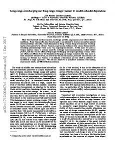
This is one of the indirect methods. Fig. 5 presents how gas pressure and flow rate along the pipeline are changing after a leak has happened.
Fig. 5. Gas pressure and flow rate after the leak. At the initial instant (t1) at the leak point a rapid Articles
41
VOLUME 1,
Journal of Automation, Mobile Robotics & Intelligent Systems
pressure drop occurs, which propagate to both sides of the pipeline. The flow rate just upstream the leak point increases, downstream this point decreases. The pressure wave propagates with the sound speed. The gas mass flow rate increases upstream the leak point (instant t2), whereas downstream this point it increases on a while, and then goes back to the primary value. After several minutes the new state of the pipeline can be observed (instant t3). Upstream the leak point the mass flow rate increases by the value of flow rate of leaking gas, and downstream returns it to the primary value. Pressure gradient along the pipeline increases upstream the leak point, and downstream the pressure gradient returns to its initial value. Method based on pressure wave detection [9] and [10] consists in pressure measurements at the selected points distributed along the pipeline. If quick pressure change caused by acoustic (pressure) wave appears, one have to verify, whether similar change will take place at subsequent points, and whether it appears in the time resulting from the acoustic velocity and the distance between measurement points. Sufficient quick pressure transducers (precision is not most important) must be installed at several kilometers intervals (Fig. 6). To ensure precise synchronization of time measurement usually the satellite navigation system GPS is used. It generates an accurate time information based on atomic clocks installed at system satellites. This method is relatively fast (the leak detection and localization time is about few seconds.
N° 3
September 2007
method makes it possible to detect and localize the leak, but it is impossible to assess directly the leak intensity unless the amplitudes of pressure waves will undergo further analysis.
Fig. 7. Leak detection system based on pressure wave detection, acc. to [11].
5. A method based on mass balance concept This concept of leak detection is based on mass conservation principle. The total quantity (mass, flow rate, volume) of fluid entering and leaving a network must be balanced by the inventory variation (accumulation) inside the network. This is apparently the simplest and most natural method. However, changes of liquid quantity, which depends on pressure and temperature, should be carefully considered. These changes are especially crucial for gas pipelines. Very important are also uncertainties and drift of flow, temperature and pressure transducers. To apply this method is necessary to calculate stepby-step current value of certain variable t(t) at regular sample intervals. For gas net with single input and n outputs (gas receiving stations), the variable t(t) for standard conditions can be written as n
Fig. 6. Leak localization method based on pressure wave detection. In the Fig. 6 the abscissa represents distance z from the beginning of pipeline 0; pressure sensors are installed at points zi. Axis of ordinates represents acoustic wave propagation time tl as a function of the distance from the leak point zl. Fig. 7 presents the scheme of such system according to [11]. Leak point is calculated as intersection point L of A-L and L-B lines. Point A denotes the time of pressure wave front transition to pipeline beginning and point B - transition time of pressure wave to pipeline end. The accuracy of leak localization is about (2 - 3)cT0 , where T0 is signal-sampling period. Therefore, signal-sampling period should be as short as possible, at least few times per second. Elimination of the stochastic noise becomes possible by the use of various types of analogue or digital filters, and especially correlation methods [9]. If the leak is not detected immediately (as a result of temporary system failure, the leak will remain undetected forever. This 42
Articles
t(t)=DVn,in(t) S DVn,out(t)DVn,a(t)
(1)
i=1
This variable t(t) may be defined as a corrected flow unbalance term at time t. This is the difference between the gas volume entering the pipeline DVn,in(t) and the volume that flowed out from the pipeline n
S DV
(t)
n,out
i=1
(where n is number of outputs, that is gas stations located along the pipeline), reduced by the volume of gas accumulated in the pipeline Vn,a(t); index n denotes standard conditions. Expression Vn,a(t) represents changes of gas content in a pipeline. It depends on pressure, temperature and gas composition. Therefore, it can be written (without taking into account the pipe elastic strain) as follows DVn,a(t)=Vgrn
pTn pnTZ
(2)
and should be calculated step by step from the average temperature and pressure values for every pipe section
VOLUME 1,
Journal of Automation, Mobile Robotics & Intelligent Systems
(branch). Vg is the geometrical volume of the pipeline, p and T - absolute pressure and temperature in the pipeline; index n as formerly, denotes standard conditions. Parameter t(t) usually fluctuates around the non-zero mean value m, due to drift of measurement instruments and gas meters errors (which depend on the flow rate) or as a result of changes of conditions (e.g. temperature along a pipeline). These fluctuations can be characte2 rized by a s variance. Let us denote Dm the instantaneous deviations from average value. To generate a leak alarm the following cumulative sum is examined: a(t)=a(t-1)+
Dm Dm t(t)-m2 s 2
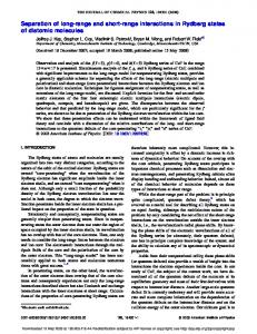
6. Gradient method Contemporary analytical methods are developed from gradient methods [12, 13, 7]. Fig. 8 shows the pressure drop along the liquid pipeline before and after leak.
S
1
in
in
p
out
tanGs DtanGk
in
in
out
out
2
Fig. 8. Pressure drop along the liquid pipeline before and after leak. Liquid is transported from a tank T1 to tank T2. In non-leak state the pressure gradient along the pipeline is constant, equal to GS (blue line). When leak begins, after new conditions were established, one can observe following phenomena: The pressure drops both at the pipeline input and output, Increase of pressure gradient upstream the leak point, Decrease of pressure gradient downstream the leak point, Increase of flow rate upstream the leak point, Decrease of flow rate downstream the leak point. Usually along a pipeline every several kilometers are situated shut-off valves assemblies, where pressure transducers integrated in the telemetry or SCADA system
-2
(4)
The flow rate of the leak can be calculated from the formula 1–
DGk Gs
1–
DGp Gs
q1=q0 1–
(5)
The situation changes in some extent in the case of gas pipelines, that is shown in Fig. 9 1
S p p
90°+ +
S 1
S
p
u u
Fig. 9. Pressure drop along the gas pipeline before and after leak. Research carried out into gas pipelines [14] shows that at the beginning of a pipeline pressure drop are negligible (Fig. 9). There also is not a decrease of gas flow rate downstream the leak point because the pipeline ends with a gas regulating station. Such stations are very tolerant to changes of input pressure, so gas flow rate is only a function of gas demand. Pressure gradient downstream the leak point changes are not noticeable. In situation like that one can approximately calculate the leak point coordinate from the formula [14]: xu=Dp(L,t)
u
1
xu=L 1+
out
k 1
September 2007
are installed. They enable to calculate pressure gradients. The coordinate of the leak point xu is then equal
(3)
The alarm is generated when the sum a(t) exceeds the given value. This value should be determined experimentally and can be changed, i.e. during technological operations producing greater disturbances of flow parameters larger acceptable value a(t) is set. To eliminate false alarms caused by slow drift of measurement transducers, one modifies m value very slowly, with the use of measurement data from periods without leaks. For the reason of relative simplicity this method is often applied even for complicated pipe networks. However, direct localization of leak point is impossible; one only can localize a section (between two measurement points) in which a leak happened.
N° 3
cosGs sin(90°–Gs–DGp) sinDGp
(6)
Pure gradient methods are effective only in steady flow conditions, without disturbances caused by change of operating conditions.
7. Analytical methods Basis of the analytical methods is modeling in the real time the phenomena inside a pipeline with the use of suitable mathematical models (modeling flow velocity as a function of pressure or pressure as a function of velocity), and comparison of the values calculated from the model with values acquired from the real pipeline. When the differences between the measured and calculated values (so called residua) are high, the alarm is generated and procedures of leak localization are activated. Both static and dynamic models are acceptable, however it must be proceeded by careful analyze. For gas the static model based on conservation of mass principle (which can be written as continuity equation) and known from hydraulics formulas for pipelines [15] has a following form: rwA=rqv=qm=const
(7) Articles
43
VOLUME 1,
Journal of Automation, Mobile Robotics & Intelligent Systems
pD qm= 4
2
2
p1 – p2
2
2ZRT ln
p1 lL + p2 2Dp
(8)
where qm – stream of mass, kg/s p1 and p2 – absolute pressure at input and output of the gas pipeline, Pa D – inner diameter of the gas pipeline, m Z – compressibility factor, dimensionless R – gas constant, J/(kgK) T – absolute temperature, K L – length of modeled gas pipeline section, m l – linear losses factor. A dynamic model for gas pipeline can be expressed by a set of partial differential equations, which may be derived from conservation of mass and conservation of momentum principles [7]
A ¶p ¶q + =0 c2 ¶t ¶z
1 ¶q ¶p lc2 qïqï g sina =p + 2 A ¶t ¶z 2DA2 p c
(9)
(10)
The resolution of dynamic model demands large processor capacity and the calculations are time consuming. It is possible to check if the dynamic model is really necessary by calculating the value of the term related to the change of momentum in time, therefore
1 ¶qm 1 ¶(rqv) ¶(rw) D(rw) (11) = » = A ¶t A ¶t ¶t Dt Comparing it with other terms of the equation. If its value is negligible, the simple static model (7,8) can be used. For liquid pipelines, because of larger transported masses, usually dynamic model [6] has to be applied. In order to describe the liquid pipeline dynamics for the modeling purposes the pipeline is arbitrarily divided into sections at xi points where measuring transmitters were installed on the real pipeline. It enables the direct comparison of the variables values obtained by simulation with the real ones, recorded in the real pipeline. Additionally, each pipeline section between xi and xi+1 points has to be divided into shorter, equal parts Dxj. Every segment fulfils a set of partial differential equations as a result of the law of mass and momentum conservation. In the case of a leak-proof pipeline (that is a pipeline for which neither mass decrement nor momentum decrement are observed) and taking into account that w(x,t)