an Android application for the creation of metro map metaphor diagrams. Dan Chivers .... http://blog.visualmotive.com/20
Metro Map Input and Layout Automation an Android application for the creation of metro map metaphor diagrams Dan Chivers School of Computing The University of Kent, UK Email:
[email protected]
Abstract—We present a system for drawing metro map style schematics using a gesture-based interface. This work is the first to bring together techniques in gesture recognition on touchsensitive devices with research in automated schematic layout. The software allows users to create and edit schematic networks, and provides an automated layout method, based upon a previous method and expanded upon, for improving the appearance of the schematic.
I.
I NTRODUCTION
Schematics are commonly used in many application areas. Typically, these have been drawn by hand using vector graphics applications, requiring a great deal of time and effort. Touchbased devices can be used for quick and effective input of data, for example sketching schematics. With this in mind our aim was to develop a piece of software to evaluate the effectiveness of using a gesture-based system to draw schematics. The application we have developed, SchemaSketch, aids users in the creation of metro map style schematics by providing an intuitive gesture input system and an automatic layout algorithm, inspired by [6] and extended in [2] and [3], that attempts to improve the aesthetic appearance of drawn schematics by modifying their layout to adhere to a set of criteria. We also extend this layout algorithm by implementing three additional criteria. An APK of SchemaSketch can be downloaded here: http://cs.kent.ac.uk/projects/schemasketch. II.
I NTERFACE AND I MPLEMENTATION
We have developed a software tool that allows a user to hand draw schematics on a touch-based device. The application, SchemaSketch, has been developed for use on Android v3.0 or higher devices. SchemaSketch supports gesture recognition to allow fast input of schematics by the user. We have examined previous work in gesture based input [5], sketch recognition and beautification of hand drawn sketches [4] in order to decide on an efficient and intuitive input mechanism for drawing schematics. Figure 1 illustrates recognised gestures which can be used to create complex metro map schematics. These gestures were designed to be similar to how one may draw each component by hand. Junctions, a node with degree of greater than two, are drawn with a circle and will connect the end of any edges within the drawn circle area together. Lines, edges that connect two junctions together, are drawn with a straight line. If either end of the drawn line lies near a junction, it will connect to it. Stations, nodes with degree of 2, drawn by a short line perpendicular to an edge will connect onto the nearest edge; and bends, a short perpendicular line returning to the start point, that connect to lines much like stations but allows lines to bend (it is desirable to not bend
(a) Junction Fig. 1.
(b) Line
(c) Station
(d) Bend
Supported gestures (cross marks the beginning of gesture)
lines at stations). Gestures are recorded as a sequence of timestamped points. When the user makes a gesture SchemaSketch will characterise it using calculated values for direct length (between start/end gesture points), gesture length (along path), straightness and average radius (distance from midpoint). Between these four metrics, each gesture can be accurately identified. We plan to formally test the accuracy of our gesture recognition system, and also implement additional gestures to control the application. Additionally, drawing multiple edges of different colours between the same two nodes will result in a parallel line segment, and touching a station will open a text input dialog allowing the user to enter a label name. Labels are initially placed below the station but will be automatically positioned during the optimisation process. Along with gesture input to draw schematic components, the software allows manual movement of all drawn components and positioning of labels, both before and after optimisation. The connection process when drawing gestures allows components to be moved by the user whilst retaining their connectivity, as affected edges will automatically adjust as nodes are moved. Manual modification can be performed both before and after optimisation which can be utilised to fix any layout issues. It is also possible to re-optimise the schematic after performing manual modifications. III.
L AYOUT AND O PTIMISATION
The automated layout algorithm in SchemaSketch expands upon a multicriteria hill-climbing optimiser technique first explained in [6]. This implementation adds the additional experimental criteria of periphery line straightness, symmetry and balance to attempt to further improve layout. There are two stages of optimisation; first the schematic itself is optimised, and then the labels are optimised. The following section explains the schematic layout criteria. A. Node Criteria Criteria for the positioning of nodes: 1) Octilinearity. Lines should be at multiples of 45◦ . 2) Edge Crossings. Lines should not cross other lines.
rn Ho rm No
y sb
h an ur
Richmond
st n or Th n Pe
h ig
le
East Richmond
H nt
na
Clarendon
ills
Windsor
Be h en elt Ch
Carlingford Telopea Parramatta
Killara Lindfield Roseville Chatswood Artamon St. Leonards Wollstonecraft
Auburn Lidcombe
d
Vil la w oo
ke m La
Sydenham Domestic Airport Marrickville
Mascot
St. James Museum
Martin Place St. PetersErskineville Green Square
Be
yP ar
k
ba
l
n
ow
st ow
ch b
W ile
Ba nk
Pu n
g ro n
lm or e Ca m ps ie Ya g Hu oo n Ca rlsto a nt n er e P b a Duury rk lw ich Hil l
Regents Berala Park
Se fto n
Milsons Point
Circular Quay Town Hall
Strathfield
Burwood
Bir
North Sydney Wynyard As hfi eld Le w ish M am ac do St nald an m tow n Ne ore w to Su wn m m Cr er H oy il do l Pe n te rs ha Ce Red m nt fe ra rn l
Waverton
North Strathfield Flemington Homebush
Liv er p
Cabramatta Warwick Farm
Dundas
Rosehill
Clyde
l Hil
nfi eld
es Ch
Le ig ht o
Olympic Park
oo
l
Carramar
te r
Yennora
Gordon
t es es W d or nc Co
Merrylands Granville
Pymble
od
Guildford Harris Park
Turramurra
Rh
Toongabbie Canley Vale Fairfield
Rydalmere
Blacktown
Camellia
l
th vil le W en tw or
ea d
Hil dle Pe n
Doonside
W es tm
Mount Druitt Rooty Hill
e nk ne yd to ba tR w nis es do De W ea M
St. Marys
d oo w
Werrington
Warrawee
st
Kingswood
Wahroonga
Ea
Pennth
Marayong Seven Hills
Waitara
g
Quakers Hill
Asquith
in
Schofields
Mount Colah
p Ep
Riverstone
Mount Kuring-gai
am
Vineyard
Emu Plains
Berowra
ft ro ec
Mulgrave
Kings Cross
Casula International Airport
Bardwell Park
Wolli Creek
Edgecliff
Glenfield Kingsgrove Bexley North
Turrella
Arncliffe
Tempe
h
to w ell
m ea Le u
pb
gle bu In
Ca m
Minto
le da ck Ro h ra ga Ko on rlt Ca ah aw All le vil rts Hu rst hu ns Pe le a td or y M atle O
rn
n
ls
d
Hil
Banksia
Bondi Junction
ee w
rly ve
Be
r Na
w to
ds Pa
oo w er Riv
ia
by
an
s ve
n Pa
y th
ls
Hil
or lsw
st
Re
Ea
Ho
Macquarie Fields
Como
Macarthur
Jannali
a ull
ow ar e
Cr on
ah
lo W oo
da
Ca r
in
gb
ea
ira n M
m Gy
Engadine Heathcote
Kir
Loftus
ra w ee
Sutherland
Waterfall
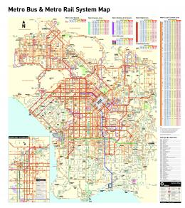
Fig. 2.
3)
4) 5) 6) 7)
Optimised Sydney schematic using our tool, exported to .svg from device.
Line Straightness: a) Total. The entirety of the line should be as straight as possible. b) Through Nodes. Lines sections passing through junctions should be kept straight. c) At Peripheries. Periphery line sections should be kept straight. Edge Length. Line sections between nodes should be a standard length. Occlusion. Nodes should not occlude parts of edges. Symmetry. The angles between incident edges should be equalised. Balance. Node density across the diagram should be equalised.
Each of the criteria defined above has its own metric for calculating a fitness value on the schematic. Using this we can calculate, weight, and sum all these values to produce a total fitness for the current schematic layout. The optimiser will attempt to reduce the total fitness value by moving nodes around and recalculating the required values. A total fitness value of zero would indicate that all criteria have been perfectly met.
schematics with gestures, as input mechanisms are typically not very accurate (e.g. a fingertip). This problem can be circumvented by allowing the user to zoom in, as gestures are perfectly suitable for input when fine detail is not required, and we plan to implement this functionality into the software. Putting this aside, we are able to use our software to quickly create schematics to our specification and are confident that gesture recognition is an effective input technique. In order to verify this, we plan on performing usability studies to test the efficiency of gesture-based input versus alternate techniques. As illustrated in [1], there is clearly a use for software that allows the drawing and optimisation of metro map style schematics, as the examples that can be found there have been time-consumingly drawn by hand. SchemaSketch allows users to draw metro map style schematics via a series of gestures, and then optimise these using both manual and automated layout tools. The automated layout algorithm implemented produces results of a good quality, but there are still a few situations where local minima and conflicts occur. We are currently experimenting with clustering techniques and optimiser parameter manipulation in an attempt to alleviate these issues. R EFERENCES
B. Label Criteria There are eight possible label positions (north, northeast, east, south-east, south, south-west, west, and northwest), and four degrees of angle for each position (horizontal, vertical, and both diagonals). Criteria for the positioning of labels includes avoiding occlusions and maintaining label position/rotation consistency with neighbours. IV.
[1]
[2]
[3]
C ONCLUSIONS AND F UTURE W ORK
Figure 2 illustrates an example of a schematic created using our software. It shows the Sydney metro map, after being optimised from its initial geographic layout and the criteria, explained in Section III, applied by the optimiser can be seen throughout this image. A current limitation of the software is the inability to zoom in/out. This can make it difficult to create detailed
[4] [5] [6]
Ten examples of the metro map metaphor. http://blog.visualmotive.com/2009/ten-examples-of-the-subway-mapmetaphor, accessed 08/05/2012. D. Chivers and P. Rodgers. Gesture-based input for drawing schematics on a mobile device. Proceedings of the Information Visualization, 15th International Conference, 2011. D. Chivers and P. Rodgers. Exploring local optima in schematic layout. Proceedings of the International Workshop on Visual Languages and Computing (VLC), 2013. M. Gusaite, E. Kazanaviˇcius, and T. Barkowsky. Dynamic scene analysis and beautification for hand-drawn sketches. Masters Thesis, 2006. D. Rubine. Specifying gestures by example. Computer Graphics, Volume 25, Number 4, pages 329–337, 1991. J. Stott, P. Rodgers, J. C. Mart´ınez-Ovando, and S. G. Walker. Automatic metro map layout using multicriteria optimization. Transactions on Visualization and Computer Graphics, 16(1), pages 101–114, 2011.


![[PDF] Streetwise Barcelona Metro Map - Google Sites](https://m.moam.info/img/260x300/pdf-streetwise-barcelona-metro-map-google-sites_6478c84e097c4796708d3031.jpg)


![Transit System Map - Metro [PDF]](https://m.moam.info/img/260x300/transit-system-map-metro-pdf_64799759098a9e9f088b459c.jpg)
