REVIEW OF SCIENTIFIC INSTRUMENTS 81, 013704 共2010兲
Microcontroller-driven fluid-injection system for atomic force microscopy S. Kasas,1,2,a兲 L. Alonso,1 P. Jacquet,1 J. Adamcik,1 C. Haeberli,3 and G. Dietler1 1
Institut de Physique des Systèmes Biologiques, Ecole Polytechnique Fédérale de Lausanne (EPFL), CH-1015 Lausanne, Switzerland 2 Département de Biologie Cellulaire et de Morphologie, rue du Bugnon 9, UNIL, CH-1005 Lausanne, Switzerland 3 Département de Physiologie, rue du Bugnon 9, UNIL, CH-1005 Lausanne, Switzerland
共Received 5 October 2009; accepted 11 December 2009; published online 15 January 2010兲 We present a programmable microcontroller-driven injection system for the exchange of imaging medium during atomic force microscopy. Using this low-noise system, high-resolution imaging can be performed during this process of injection without disturbance. This latter circumstance was exemplified by the online imaging of conformational changes in DNA molecules during the injection of anticancer drug into the fluid chamber. © 2010 American Institute of Physics. 关doi:10.1063/1.3285262兴
I. INTRODUCTION
The atomic force microscope is a relatively new instrument,1 which permits the high-resolution imaging of biological samples under near-physiological conditions. It consists of a cantilever-mounted sharp tip which scans the surface of the sample. The instrument operates equally well in a vacuum, air or a liquid. The possibility of recording high-resolution images in a fluid medium renders the tool an invaluable one for biologists.2 Although almost all commercially available instruments are equipped with a chamber for liquids, the fluid cells are not furnished with a satisfactory and convenient system for exchanging the medium during imaging. The fluid cell which holds the cantilever is usually made of glass and channels for the exchange of medium. To perform this process safely, the space between the fluid cell and the sample should first be sealed with an O-ring. Liquids in the imaging chamber can then be exchanged either by gravity or via a pump. However, the O ring drastically reduces the freedom of motion of the sample in the x-y plane and renders difficult the elimination of air bubbles. To circumvent these two drawbacks, some users renounce on the possibility of exchanging the fluid and operate the fluid cell without an O-ring. This is feasible because the capillary forces between the sample and the fluid cell are sufficiency strong to hold the liquid between these two surfaces. Using such a setup, we earlier proposed a system whereby the imaging medium could be exchanged notwithstanding the absence of an O-ring.3 It involves the use of two manually operated syringes, whose pistons are mounted back to back. A simultaneous movement of the two pistons permits an equal volume of fluid to be injected into and aspirated from the fluid cell. Although the system is well adapted for the imaging of large samples, such as living cells, the vibration induced by a manual displacement of the pistons generates a considerable amount of noise, which is incompatible with a兲
Author to whom correspondence should be addressed. Electronic mail:
[email protected].
0034-6748/2010/81共1兲/013704/3/$30.00
high-resolution imaging. Using the same principle, we therefore developed an alternative system with motorized piston pullers. It is driven by a microcontroller, which permits an adjustment of the injection parameters, such as the rate of fluid flow and the volume of liquid to be injected. The system was so designed to minimize mechanical and electromagnetic noise. It is sufficiency “silent” to render possible imaging at the molecular level. This circumstance was exemplified by monitoring conformational changes in DNA molecules during the injection of an anticancer drug into the fluid cell. II. BASIC PRINCIPLE AND SETUP
In Figs. 1 and 2 the principal components of the injection system are represented schematically. It consists of four injecting and four aspirating syringes, which are mounted back to back. The piston of each injecting syringes is mechanically coupled to that of the corresponding aspirating syringe. A removable mechanical device holds the two pistons together 共Fig. 1兲. This connecting device is attached to motor-driven headless screws which permits a linear displacement of the pistons. The motor-selection criteria were smallest possible size and minimum possible electromagnetic and mechanical noise. To this end, dc motors 共1224 006 SR, Faulhaber兲 were mounted, which are known to generate less electromagnetic noise than their stepper counterparts. Each of the four motors has a nominal torque of 1.8 mNm. They are connected to four endless screws via 1:235 dividers 共spur gear-heads series 12/3, Faulhaber兲, which reduce the rotation speed. Each motor is also equipped with a rotation counter 共Magnetic encoder 30B20, Faulhaber兲. This device conveys its information 共10 pulses/revolution兲 to the microcontroller which continually monitors the position of each piston. Two sensors 共A1101-EUA-T, Allegro MicroSystems Inc. MA, USA兲, one at each end of the traveling range, permit an automatic stoppage of the motor. A PIC 18F452–1/P microcontroller 共Microchip Technology, Inc.兲 represents the core of the electronic circuit that
81, 013704-1
© 2010 American Institute of Physics
Downloaded 22 Mar 2010 to 128.178.66.186. Redistribution subject to AIP license or copyright; see http://rsi.aip.org/rsi/copyright.jsp
013704-2
Rev. Sci. Instrum. 81, 013704 共2010兲
Kasas et al.
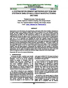
FIG. 1. 共Color online兲 Scheme of the injection/aspiration unit 1: rotation encoder; 2: aspirating syringe; 3: removable connecting clamp; 4: injecting syringe; 5: headless screw; 6: gear box; 7: motor.
powers the injection system 共see Fig. 3兲. It drives the motors, controls the position of the pistons, and oversees the user interface. The interface is compromised of a four-line liquid crystal display and seven buttons to adjust the injection parameters. The adjustable parameters are: 共a兲 the motor to be activated 共1–4兲; 共b兲 its direction of rotation; 共c兲 its speed of rotation 共whereby the rate of fluid flow can be varied between 0 and 1000 l / min兲; and 共d兲 the duration in seconds of its activity 共whereby the volume of fluid to be injected can be varied between 0 and 1 ml兲. It should be noted that the motors neither start nor stop abruptly. To avoid any electromagnetic or mechanical perturbation that could compromise the image-acquisition process they accelerate and decelerate gradually. The interface is equipped with an emergency button which permits an immediate 共decelerating兲 stoppage of the injection process. The microcontroller drives the motors via the mediation of four motor-controlling circuits 共Motor Mind B enhanced Motor Controller, Solutions Cubed, LLC, CA, USA兲. The microcontroller is programmed in BASIC and the program is compiled with a PICBASIC PRO compiler 共MicroEngineering Laboratories, Inc.兲; and its code is comprised approximately of 1350 lines. We chose a syringe capacity of 1 ml, which suffices for most experimental purposes but the system is adaptable. Two additional but manually operated syringes 共Fig. 2兲 are connected to the common input and output tubing. Their function is to adjust the liquid level in the imaging chamber at the onset of an experiment. Additional tubing is connected via a valve to the common aspiration tube 共Fig. 2兲. When the valve is opened, this additional tubing permits circumvention of the aspirating syringe and an increase in the volume of fluid within the imaging chamber, which may be required to compensate for evaporation.
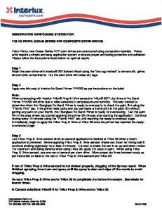
FIG. 2. 共Color兲 Scheme of the hydraulic circuit 1: manually operated valve; 2: Plexiglas fluid chamber; 3: fluid cell; 4: manually operated injecting syringe; 5: injecting syringe; 6: aspirating syringe; 7: manually operatedaspirating syringe; 8: manually operated valve.
FIG. 3. 共Color兲 Photograph of the injection system and of its electronic driving unit.
III. EXPERIMENTS A. Characterization of the noise generated while operating the injection system
To gauge the noise level generated by the injection system during its operation topographic images of an atomically flat surface were recorded in the atomic force microscope. With a surface roughness of less than 1 nm mica is a suitable substrate for the measurement of fluctuations in noise. For this purpose a Nanoscope III 共Veeco Instruments, Santa Barbara, CA兲 was operated in the so-called tapping mode. Using water as the observation medium, images of the mica surface were recorded under continuous fluid flow, with flow rates ranging from 0 – 500 l / min. The images were acquired at a scanning rate of 1 or 2 lines/s. The cantilever with a nominal spring constant of 0.32 N/m, was driven at frequencies between 7 and 12 kHz. The noise generated was quantified by measuring the root mean square 共rms兲 of the amplitude of the recording. Figure 4 reveals the existence of a directly proportional relationship between the level of noise that is generated by the injection system and the rate of fluid flow. Albeit so, even at the highest available flow rate, the maximum rms value attained, namely, 0.2 nm, was astonishingly low.
FIG. 4. Bar graph depicting the relationship between the rms of the amplitude 共noise level兲 of the recording on a flat mica substratum and the rate of fluid flow 共0 – 200 l / min兲. Mean values 共n = 9 images兲 are represented together with the standard error of the mean.
Downloaded 22 Mar 2010 to 128.178.66.186. Redistribution subject to AIP license or copyright; see http://rsi.aip.org/rsi/copyright.jsp
013704-3
Rev. Sci. Instrum. 81, 013704 共2010兲
Kasas et al.
B. Air bubbles issue
Another important issue is the trapping of air bubbles inside the fluid cell, which could seriously disturb the operation of the microscope. In our injection system operated without O-ring, incoming air bubbles are immediately trapped at the air/liquid interface of the meniscus, thus no air bubbles are cumulated in the fluid cell C. Online imaging of conformational changes in DNA molecules during the injection of an anticancer drug
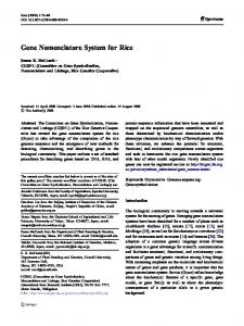
To test the efficiency of our injection system in a biologically relevant situation, we recorded online the effect of an anticancer drug on the conformation of double-stranded DNA. we chose daunorubicin, which is used to treat several types of cancers, such as leukemias and neuroblastomas. This agent intercalates in double-stranded DNA thereby modifies its coiling state. The application of daunorubicin to plasmids of Escherichia coli elicits an increase in their supercoiling density from negative to positive values.4,5 For our experiments, we used the pBR322 plasmid 共Fermentas, MD, USA兲, which is a negatively supercoiled doublestranded DNA molecule. A suspension of the plasmid 共10 ng in a solution containing 10 mM TRIS, 2 mM MgCl2, and 10 mM NaCl兲 was deposited on a substratum of mica which had been pretreated with 1 mM NiCl2.6,7 TRIS-buffered EDTA served as the imaging medium. For this type of imaging, the DNA molecules must be attached with sufficient strength to permit their observation in the atomic force microscope but not too strongly as to impede the daunorubicin-induced conformational change. Since the conformational change occurs as soon as the drug enters the observation chamber, the injection must be very “quiet” to avoid a disturbance in imaging and a flow-induced movement of a DNA molecule out of the field of view. The images were acquired using tapping mode and at a rate of 2 lines/s. The cantilever with a nominal spring constant of 0.32 N/m was driven at frequencies between 7 and 12 kHz. Figure 5 displays sequential changes in the conformation of a double-stranded DNA molecule during the injection of daunorubicin. After injection of 2 l of the drug into the fluid cell the plasmids proceed through a series of transitions in which their degree of negative supercoiling decreases and then reverses to form local positive plectonemes. It can also be noted that in the last frames before injection that the positive supercoiling seriously restricts the conformational fluctuations of the DNA plasmid. IV. CONCLUSIONS
We have developed an injection system for the exchange of imaging medium during observations in the atomic force microscope. It has been tailored for use in conjunction with Veeco’s fluid cells, and has been optimized to generate the
FIG. 5. 共Color兲 Nanoscale time-lapse imaging of a suspension of doublestranded DNA 共the pBR322 plasmid兲 in an atomic force microscope before, during, and after the injection of the anticancer drug daunorubicin 共2 M兲. The elapsed time, expressed in seconds, before 共negative values兲 and after 共positive values兲 the injection of 5 l of daunorubicin into the fluid cell 共at t = 0兲 is indicated above each image. The arrows in the last frame indicate the position at which positive supercoiled plectonemes are formed. Scan sizes correspond to 625 nm 共256⫻ 256 pixels兲.
lowest possible levels of electromagnetic and mechanical noise 共with a rms value for fluctuations in amplitude during injection of ⬍0.2 nm兲. The efficiency of the system was demonstrated by the online imaging of conformational changes in double-stranded DNA during the injection of an anticancer drug 共daunorubicin兲 into the imaging chamber. Since little information is available concerning either the nature or the temporal course of daunorubicin-induced conformational changes in double-stranded DNA, these atomic force microscope observations could bring to light valuable information. Although the system has been established for use in the absence of an O-ring, such an appliance can nevertheless be fitted if the injection of small fluid volumes 共a few microliters兲 is called for. The system can also be adapted for use in conjunction with a bioscope 共models I or II兲. When using either of these instruments, the injection system maintains the volume of fluid in the Petri dish at a constant level during the exchange process. ACKNOWLEDGMENTS
This work was supported by the Swiss National Science Foundation Grant NB 共Grant No. 200021-118147兲. G. Binnig, C. F. Quate, and C. Gerber, Phys. Rev. Lett. 56, 930 共1986兲. S. Kasas, N. H. Thomson, B. L. Smith, H.G. Hansma, J. Miklossy, and P. K. Hansma, Int. J. Imaging Syst. Technol. 8, 151 共1997兲. 3 S. Kasas, X. Wang, H. Hirling, S. Catsicas, C. Haeberli, G. Dietler, and N. Thomson, Rev. Sci. Instrum. 71, 4338 共2000兲. 4 X. L. Yang and A. H. J. Wang, Pharmacol. Ther. 83, 181 共1999兲. 5 V. Víglasky, F. Valle, J. Adamcik, I. Joab, D. Podhradsky, and G. Dietler, Electrophoresis 24, 1703 共2003兲. 6 N. H. Thomson, S. Kasas, B. Smith, H. G. Hansma, and P. K. Hansma, Langmuir 12, 5905 共1996兲. 7 O. Piétrement, D. Pastre, S. Fusil, J. Jeusset, M. O. David, F. Landousy, L. Hamon, A. Zozime, and E. Le Cam, Langmuir 19, 2536 共2003兲. 1 2
Downloaded 22 Mar 2010 to 128.178.66.186. Redistribution subject to AIP license or copyright; see http://rsi.aip.org/rsi/copyright.jsp