Lab on a Chip View Article Online
Published on 13 June 2013. Downloaded by University of Pennsylvania Libraries on 21/06/2013 04:24:09.
PAPER
Cite this: DOI: 10.1039/c3lc50493j
View Journal
Microfluidics embedded within extracellular matrix to define vascular architectures and pattern diffusive gradients Brendon M. Baker, Britta Trappmann, Sarah C. Stapleton, Esteban Toro and Christopher S. Chen* Gradients of diffusive molecules within 3D extracellular matrix (ECM) are essential in guiding many processes such as development, angiogenesis, and cancer. The spatial distribution of factors that guide these processes is complex, dictated by the distribution and architecture of vasculature and presence of surrounding cells, which can serve as sources or sinks of factors. To generate temporally and spatially defined soluble gradients within a 3D cell culture environment, we developed an approach to patterning microfluidically ported microchannels that pass through a 3D ECM. Micromolded networks of sacrificial conduits ensconced within an ECM gel precursor solution are dissolved following ECM gelation to yield functional microfluidic channels. The dimensions and spatial layout of channels are readily dictated using photolithographic methods, and channels are connected to external flow via a gasket that also serves to house the 3D ECM. We demonstrated sustained spatial patterning of diffusive gradients dependent on the architecture of the microfluidic network, as well as the ability to independently populate cells in either the channels or surrounding ECM, enabling the study of 3D morphogenetic processes. To highlight the utility of this approach, we generated model vascular networks by lining the channels with endothelial cells and examined how channel architecture, through its effects on diffusion patterns, can guide the location and
Received 18th April 2013, Accepted 7th June 2013
morphology of endothelial sprouting from the channels. We show that locations of strongest gradients define positions of angiogenic sprouting, suggesting a mechanism by which angiogenesis is regulated in vivo and a potential means to spatially defining vasculature in tissue engineering applications. This flexible
DOI: 10.1039/c3lc50493j
3D microfluidic approach should have utility in modeling simple tissues and will aid in the screening and
www.rsc.org/loc
identification of soluble factor conditions that drive morphogenetic events such as angiogenesis.
Introduction In addition to serving as a physical support for cells, the extracellular matrix (ECM) plays an integral role in regulating the distribution of nutrients, gases such as oxygen and nitric oxide, and soluble effectors including morphogens, growth factors, hormones, and cytokines. Gradients of such molecules are essential in regulating numerous fundamental biological processes: progenitor cell differentiation and tissue patterning during development,1,2 angiogenesis that accompanies tissue repair in the adult,3,4 and tumor cell invasion and homing responsible for metastatic disease.5 In all of these processes, the spatial presentation of diffusible factors in tissues is complex, largely dictated by the distribution and morphology of vascular structures, as well as the structure and porosity of
Tissue Microfabrication Lab, Department of Bioengineering, University of Pennsylvania, Philadelphia, PA 19104, USA. E-mail:
[email protected]; http://www.seas.upenn.edu/~chenlab/index.html; Fax: +1 215 746-1752; Tel: +1 215 746-1754
This journal is ß The Royal Society of Chemistry 2013
the surrounding ECM and the density and metabolic activity of surrounding cells.6 Studying these intricate processes and their dependencies on diffusible gradients in vitro is significantly aided by microfluidic approaches, which enable a high degree of control over the timing and spatial presentation of biological factors.7–9 Numerous devices exist to elegantly and precisely control the soluble factors overlying cells plated on 2D surfaces,10,11 however fewer systems exist for defining soluble factor presentation to single cells or multicellular structures fully embedded within a 3D matrix. It is now well established that native cell–cell and cell–ECM interactions can be better recapitulated in 3D culture settings.12 Indeed, the higher order morphogenetic events described above are impossible to capture on 2D surfaces, as these processes require cells to invade, remodel, or otherwise reconfigure the 3D scaffold. As such, microfluidic devices have been developed for applying a gradient to cells embedded within ECM.13–15 As gradients of soluble factors are heavily implicated in angiogenesis, recent efforts have focused on exposing endothelial structures to
Lab Chip
View Article Online
Published on 13 June 2013. Downloaded by University of Pennsylvania Libraries on 21/06/2013 04:24:09.
Paper gradients of angiogenic factors.16–19 However, many of these previous approaches place microfluidic channels at the outer edge of the ECM, thereby limiting gradients to relatively simple fields and constraining the shape and path of endothelialized vessels and subsequent direction of invasion. Others that have placed fluidic channels within the ECM itself have limited their studies to rectilinear channel patterns.13,20 Thus, the ability to generate more complex network architectures and study their effects on endothelial cells has not yet been explored. Here we generate complex diffusion patterns of soluble factors during long-term morphogenetic processes by shaping the vasculature that pervades the surrounding 3D ECM. To generate temporally and spatially defined soluble gradients with more complex geometries, we developed an approach to patterning ported microchannels within a 3D ECM. Lithographically-defined sacrificial channel structures were micromolded in gelatin on top of a glass slide, ensconced within a collagen gel precursor solution, and subsequently dissolved following collagen gelation to yield a microfluidic network embedded within 3D ECM. These microfluidic channels were connected to controlled external flow or media reservoirs via a gasket which also served to house the 3D ECM. Individual cell populations were encapsulated within the gel precursor or seeded inside the resulting channels to define stromal and endothelial cell populations, respectively. By defining channel geometries, diffusive gradients were spatially patterned, enabling the study of biological processes that occur in a 3D setting under the guidance of complex gradients of soluble factors, such as endothelial sprouting during angiogenesis. We used this approach to examine how the geometry of endothelial vasculature alters the spatial patterning of diffusive gradients and in turn influences the resulting invasion of endothelial cells during angiogenic sprouting.
Experimental Device fabrication Gelatin channel templates and gaskets were fabricated by casting poly(dimethylsiloxane) (PDMS; Sylgard 184; DowCorning) off silicon wafer masters possessing SU-8 photoresist structures (Microchem) generated by standard photolithography. Masks were designed in Adobe Illustrator and are provided in the supplementary information. Following curing, PDMS gaskets were removed from the master and ports or reservoirs were cut with biopsy punches of varying diameters. Gaskets and glass slides were exposed to oxygen plasma to render surfaces hydrophilic and immediately treated with sequential 2 h incubations in 0.1 mg ml21 poly-L-lysine (Sigma) and 5% v/v glutaraldehyde (Sigma) to crosslink the eventual collagen gel to the gasket walls. Following surface treatment, PDMS templates defining the gelatin channel were applied to the glass slide and a warmed 10% w/v gelatin solution (from porcine skin, Sigma) was drawn through the channel template and allowed to solidify prior to removal of the stamp. Separation of the PDMS stamp from the glass slide
Lab Chip
Lab on a Chip frequently occurred when introducing gelatin via positive pressure, but manually applied suction could achieve the same result without separation occurring. The surface-treated gasket was then registered upon the gelatin channel structure and a solution of rat tail collagen I (BD Biosciences, prepared as in21) was pipetted into the central chamber and allowed to gel at RT for 30 min. The assembled device was then incubated at 37 uC to melt the gelatin structure, thereby leaving open channels in the persisting collagen gel. Device validation To confirm that channels were open and free of leaks, 3 mm fluorescein polystyrene microspheres (Polysciences) were introduced into the reservoirs and the flow of microspheres due to hydrostatic pressure was examined by epifluorescence. In order to characterize the formation and stability of diffusive gradients, 200 mm thick devices were fabricated with a 6 mg ml21 collagen gel containing a single branched channel initiating from two open media reservoirs and a single outlet port (Fig. 1D). Reservoirs were filled with 250 mg ml21 solutions of 110 kDa fluorescein-conjugated dextran (Sigma) and PBS. A syringe pump was connected to the outlet and fluid was withdrawn at 20 ml h21. The resulting diffusion of fluorescent dextran within the central portion of the device was imaged once every 10 min for 12 h on a Nikon Ti Eclipse epifluorescent microscope. Fluorescence intensity across the device was quantified with FIJI. Cell culture For endothelial sprouting studies, devices were generated with 500 mm-thick 3 mg ml21 collagen gels containing two independent channels terminating in open media reservoirs (Fig. 1C). HUVECs were purchased from a commercial source (Lonza) and expanded to passage 6–8 in EGM-2 (Lonza) prior to use. One of the two channels was endothelialized with HUVECs by pipetting a concentrated cell suspension (5 6 106 cells ml21) into reservoirs and carefully inverting the device onto parafilm, in order to seed the top and sides of the channel. Following an hour long static incubation at 37 uC to allow for HUVEC adhesion to the channel walls, all reservoirs were filled with EGM-2 and the devices were placed on a platform rocker (BenchRocker, BR2000) at 0.1 Hz overnight. The following day, the reservoirs of the endothelialized channel were replenished with EGM-2 and the reservoirs of the acellular channel were replenished with EGM-2 supplemented with 50 ng ml21 vascular endothelial growth factor (VEGF, R&D), 50 ng ml21 basic fibroblast growth factor (bFGF, R&D) and 50 ng ml21 phorbol myristate acetate (PMA, Sigma) to facilitate HUVEC sprouting as described in ref. 17. In additional studies, NIH 3T3s were expanded to passage 10, trypsinized, and resuspended in the collagen gel precursor solution prior to injection into the device. Sprout imaging To image sprout structures, devices following six days of culture were fixed in 4% v/v paraformaldehyde and stained with phalloidin-Alexa488 (Life Technologies) and DAPI (Sigma) for filamentous actin and nuclei, respectively. In additional studies, separate populations of HUVECs were fluorescently
This journal is ß The Royal Society of Chemistry 2013
View Article Online
Published on 13 June 2013. Downloaded by University of Pennsylvania Libraries on 21/06/2013 04:24:09.
Lab on a Chip
Paper
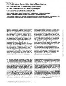
Fig. 1 A flexible approach to forming 3D collagen microfluidics. (A) Schematic overview of fabrication process for forming microfluidic channels within collagen gels. Briefly, sacrificial gelatin structures are micromolded on a glass surface, a gasket possessing porting and a central chamber for the collagen gel is registered upon the gelatin structure, collagen is introduced and gelled, and the device is incubated at 37 uC to extract the gelatin to leave open channels. Subsequently, connections to device ports or media reservoirs are made and flow is initiated. (B) Glutaraldehyde treated device surfaces crosslink the collagen gel to the gasket and ensure a leak free system. Schematic depicts locations of images showing flow of fluorescent microspheres (i–iv). (C, D) Device design is flexible and can consist of single or multiple channels, with channels terminating in open reservoirs or tubing connection ports. Shown as example is the two-channeled device with media reservoirs used for long-term sprouting studies (C) and the branched channel used for gradient characterization (D). Co-registered masks (channel template in white, gasket in black), and the assembled device after perfusion of dyes are shown for each example. (E) Channel geometries can readily be altered. Fluorescent microspheres flowing through four different channel geometries.
labeled with cell trackers CMPTX and CMFDA following the manufacturer’s instructions (Life Technologies) prior to seeding into devices. Confocal images were acquired with a Zeiss LSM 710 system and lower magnification images were acquired on a Nikon TE200 epifluorescence microscope. Maximum projections were generated using Zen software (Zeiss). For sprouting quantification, 46 images of multiple DAPI-stained devices (n = 4) were thresholded, co-registered, and averaged to generate heat maps using custom Matlab scripts.
2D models were generated by importing device geometries directly from lithographic masks created in Adobe Illustrator. Model parameters including the permeability (5.5 6 10214 m2) and porosity (99.6%) of the surrounding collagenous matrix, diffusivity (1 6 1029 m2 s21) of the solute, and flow rates within the channels (10 nl s21) were defined.22,23 Predicted steady state diffusive patterns are presented.
Modeling
Device design and rationale
The COMSOL Multiphysics suite (version 4.2) was used to model steady state diffusion patterns as a function of channel geometry. Initially, 3D models were generated to examine depth dependencies and to confirm that 2D simplifications could faithfully capture the 3D phenomenon. Subsequently,
We developed a simple and flexible method of generating microfluidic channels within 3D gels. The method involves a two-layered fabrication approach founded on the use of sacrificial templates for forming channels, around which an ECM is polymerized before the template is removed24 (Fig. 1A).
This journal is ß The Royal Society of Chemistry 2013
Results and discussion
Lab Chip
View Article Online
Published on 13 June 2013. Downloaded by University of Pennsylvania Libraries on 21/06/2013 04:24:09.
Paper We illustrate this approach using gelatin as the sacrificial material and purified type I collagen gels as the ECM. Collagen matrices are commonly used for studying numerous 3D cellular processes,25 and gelatin was selected due to its gelation dynamics which inversely complement the thermally-induced precipitation of collagen gels. Gelatin is first drawn into PDMS microfluidic channels placed upon a glass surface, gelled, and the PDMS channels are removed. A gasket possessing a central chamber to house the eventual ECM is then registered upon the gelatin structures and collagen is injected into the chamber and gelled. The micromolded gelatin structures are then melted, thereby leaving functional channels behind. Subsequently, connections are made to the device ports on the gasket, mediating mechanically stable connections between external fluid sources and the delicate gel. The internal walls of the devices are surface-treated with glutaraldehyde to covalently bind the collagen gel to the gasket, ensuring a leak free system as demonstrated by the controlled flow of fluorescent microspheres through the device (Fig. 1B). To illustrate the broad utility and flexibility of this approach, devices were fabricated with multiple independent channels terminating in open reservoirs suitable for long-term culture studies (Fig. 1C) or a single branched channel with ported outlets for connection to external pumps (Fig. 1D) with a variety of different channel geometries and sizes (Fig. 1E). Given the simplicity of the process, this approach is well suited for creating devices with application-specific channel architectures and porting. Furthermore, although purified collagen was used in developing this system, any ECM could be used with this approach. Production and prediction of controlled and sustained gradients in 3D gels We used the device possessing a branched channel and single outlet (Fig. 1D) to demonstrate the ability to generate spatially controlled, sustained gradients within 3D ECMs. Previous work established this design as a means by which low resolution syringe pumps can be used to generate balanced fluid flow in two channels, resulting in a diffusive gradient within the gel spanning the two channels.14 However, in contrast to numerous previous devices in which the channels were defined by PDMS, our fluidic channels exist within the matrix itself. To visualize gradients, one reservoir was filled with PBS containing fluorescent dextran and the other was filled with PBS, fluid was withdrawn from the device at a constant flow rate, and time-lapse imaging was performed as the diffusive gradient established over the course of 12 h (Fig. 2A). The point of convergence between the two channels revealed balanced, laminar flow (Fig. 2B). Shifting of this interface up or down would provide an indirect but convenient means of detecting mismatched channel flow rates that would drive convective flow across the ECM between the two channels and therefore disrupt a diffusive gradient. Fluorescence intensity quantified across the central portion of the device demonstrated the gradient’s profile and time to equilibration (Fig. 2C). As with native tissues, solute diffusion kinetics and resulting diffusion patterns within these fluidic devices depend on the channel architecture, characteristics of the
Lab Chip
Lab on a Chip
Fig. 2 Formation of controlled and sustained gradients in 3D. (A) Schematic depicting experimental setup and regions of images in panels B–C. (B) Point of convergence of branched channel demonstrating balanced, laminar flow of PBS with (top channel) and without (bottom channel) fluorescent dextran. (C) Timelapse imaging of the central portion of the device was performed. Shown are images from six time points taken from the series. Note that the exposure duration was dramatically reduced relative to B to avoid intensity saturation. (D) Intensity plots (taken along the red line in C) demonstrating the profile and time to equilibration of the diffusive gradient.
solute, and porosity of the ECM. To guide the design of channel architectures that would yield specific diffusion patterns, we used a modeling approach to predict steady state diffusion patterns. Device geometries were imported into the COMSOL Multiphysics platform and parameters including the porosity and pore size of the surrounding gel, the size of the solute, and the flow rates within each channel were defined to mimic our experimental setup. We found good agreement between experimental and theoretical gradients resulting from parallel and converging channels (Fig. 3A and B), suggesting that the computational approach was indeed predictive and valid. Modeling the fully 3D distribution of diffusive factors in parallel channel devices ranging in height between 400 and 1200 mm thickness revealed that gradients persisted throughout the depth of the gel, even at a ratio of 1 : 6 between the channel height and ECM thickness (Fig. 3C). Modeling of more intricate channel geometries at different flow rates revealed the potential for generating complex diffusion patterns (Fig. 3D). To prevent convective flow, symmetry was main-
This journal is ß The Royal Society of Chemistry 2013
View Article Online
Published on 13 June 2013. Downloaded by University of Pennsylvania Libraries on 21/06/2013 04:24:09.
Lab on a Chip
Paper
Fig. 4 Straightforward incorporation of cellular components provides a means for fabricating simple microfluidic models of tissues. (A) Schematic of a model tissue containing multiple endothelialized tubules (pink and green) traversing a stromal compartment containing mesenchymal cells (blue). Dashed line indicates the presence of a glass surface. (B) Confocal image of DAPI labeled 3T3s (blue) and two populations of HUVECs labeled with Cell Tracker dyes (pink and green) incorporated directly into the gel and seeded along the channels, respectively. (C) Following seeding, HUVECs spread and proliferate, resulting in confluent monolayers within the open microfluidic channels.
Engineering tissues for studying 3D morphogenetic processes
Fig. 3 Theoretical modeling can aid the design of temporally and spatially complex diffusive patterns. (A) Comparison of experimental and theoretical gradients resulting from two parallel channels shows good agreement. Phase contrast (left) and heat map-converted fluorescent (center) images following 12 h of flow of fluorescent dextran in comparison to steady state model predictions (right). (B) Comparison of experimental and theoretical gradients generated from two converging channels. (C) Diffusive gradients persist through the depth of the device, largely independent of device thickness. Model predictions of steady state diffusion patterns in parallel channel devices of 400 and 1200 mm thickness. (D) Model predictions of steady-state diffusive patterns resulting from different channel geometries (top) and varying flow rates within the same channel geometry (bottom).
tained across the various source and sink channel architectures employed in this work. However, mismatching path lengths can be designed to engineer points of controlled interstitial pressure drops and resulting convective flow.
This journal is ß The Royal Society of Chemistry 2013
A major application for this fluidic platform is as a means for modeling simple tissues possessing endothelialized vessels surrounded by a stromal space (Fig. 4A). To illustrate the potential to incorporate various cellular components, devices were formed with 3T3 fibroblasts suspended in the collagen solution (modeling interstitial cells and space) and subsequently seeded with HUVECs in the channels (modeling the vascular endothelium) (Fig. 4B). With culture, the endothelial cells proliferated and formed a confluent monolayer within the channels (Fig. 4C), consistent with previous reports.26 Given that angiogenesis is known to be driven by gradients of a variety of soluble effectors,4 we sought to examine how channel geometry and resulting diffusion patterns of growth factors (GF) influence endothelial invasion and sprouting. Endothelialized channels with different geometries were fabricated and gradients of soluble angiogenic GFs were formed in long-term culture. After six days, 3D cellular invasion into the surrounding ECM was evident as determined by DAPI stained devices (Fig. 5A). Invasion occurred uniformly along the channel in devices with parallel channels, in contrast to devices with non-parallel channels where locations of focused invasion coincided with points where the GF gradient was steepest. The ability to pattern soluble gradients and thereby define locations of angiogenic sprouting could have significant utility in tissue engineering applications, for example in cases where vasculature is required only in precise locations within a tissue construct. Furthermore, the specification of sprouting location through the architecture of the vasculature demonstrates a potential mechanism by which angiogenesis is spatially regulated in vivo. Although parallel channels provide a uniform gradient across an ECM that can offer a means to study how cell function is regulated by a specific gradient, other channel geometries offered by the flexibility of our approach allows one to explore a well-defined range of gradients. Using such an approach, we examined how the steepness of a GF gradient impacts invasion depth and sprouting morphology. HUVECseeded devices were fabricated with converging channels
Lab Chip
View Article Online
Published on 13 June 2013. Downloaded by University of Pennsylvania Libraries on 21/06/2013 04:24:09.
Paper
Lab on a Chip
Fig. 5 Channel geometries and resulting diffusion patterns dictate the location and morphology of 3D endothelial sprouting. (A) 3D invasion of DAPI stained HUVECs following 6 days of culture in the presence of a chemokine and GF gradient. In all devices, the chemokine and GF cocktail was supplemented to the acellular channel (bottom, outlined in dashed lines) while endothelialized channels (top) were maintained in basal media. Invasion depth and sprouting morphology was examined within the converging channel device (rightmost in panel (A)), which generates a diffusion pattern subjecting cells to a range of GF gradients. (B) Images of multiple DAPI stained devices (n = 4) were co-registered to generate a heat map, overlaid upon the steady state diffusion pattern (green). (C) Invasion depth quantified across the converging channel device over a range of GF gradients (n = 4 devices, error bars denote standard deviations). (D) Maximum projections from confocal z-stacks of phalloidin (red) and DAPI (blue) stained HUVEC invasion at positions denoted in (A).
which subject cells to a 4-fold range of concentration gradients, analogous to existing 2D devices.27 Fluorescent images of multiple devices were co-registered to generate a heat map (Fig. 5B). Invasion depth quantified across the converging channel device revealed a non-linear relationship between invasion depth and the strength of the GF gradient (Fig. 5C). Furthermore, confocal imaging performed at different positions along the length of the channel revealed that the morphology of the invasive structures varied considerably (Fig. 5D). Invading endothelial cells under sharper GF gradients formed multicellular structures with high cell density that lacked organization. At lower gradients, single cells or clusters of several cells were observed to migrate into the collagen gel, but stalk-like multicellular structures were not observed. Finally, at intermediate GF gradients, multicellular, stalk-like structures were observed to sprout in the direction of the gradient (Fig. 5Dii). Taken together, these results suggest the existence of optimal GF gradients that promote cohesive multicellular sprouting, and establish a rapid means towards identifying such conditions.
channel geometries influences diffusion patterns which can in turn guide 3D morphogenetic processes such as endothelial sprouting. This generalizable 3D microfluidic approach adaptable to other sacrificial materials28 should have utility in modeling simple tissues containing stromal and epithelial compartments and can aid in the screening and identification of soluble factor conditions that drive morphogenetic events such as endothelial sprouting.
Summary
References
In summary, a multilayered, sacrificial channel template approach was developed to form microfluidic channels within a collagen gel for studying 3D cellular processes mediated by diffusive gradients. Following device validation, we showed through experimental and theoretical approaches how altering
Lab Chip
Acknowledgements This work was supported in part from grants from the National Institutes of Health (grant numbers EB00262, EB08396, HL73305, GM74048) and Center for Engineering Cells and Regeneration of the University of Pennsylvania. B.M.B. acknowledges financial support from a Ruth L. Kirschstein National Research Service Award. S.C.S. is supported by R25 CA101871-07 from the National Cancer Institute. E.T. is an HHMI fellow of the Life Sciences Research Foundation.
1 J. B. Gurdon and P. Y. Bourillot, Nature, 2001, 413, 797–803. 2 H. L. Ashe and J. Briscoe, Development, 2006, 133, 385–394. 3 R. H. Adams and K. Alitalo, Nat. Rev. Mol. Cell Biol., 2007, 8, 464–478. 4 P. Carmeliet and R. K. Jain, Nature, 2011, 473, 298–307.
This journal is ß The Royal Society of Chemistry 2013
View Article Online
Published on 13 June 2013. Downloaded by University of Pennsylvania Libraries on 21/06/2013 04:24:09.
Lab on a Chip 5 R. R. Kay, P. Langridge, D. Traynor and O. Hoeller, Nat. Rev. Mol. Cell Biol., 2008, 9, 455–463. 6 L. G. Griffith and M. A. Swartz, Nat. Rev. Mol. Cell Biol., 2006, 7, 211–224. 7 S. Kim, H. J. Kim and N. L. Jeon, Integr. Biol., 2010, 2, 584–603. 8 S. Chung, R. Sudo, V. Vickerman, I. K. Zervantonakis and R. D. Kamm, Ann. Biomed. Eng., 2010, 38, 1164–1177. 9 B. J. Kim and M. Wu, Ann. Biomed. Eng., 2012, 40, 1316–1327. 10 G. A. Cooksey, C. G. Sip and A. Folch, Lab Chip, 2009, 9, 417–426. ´mez-Sjo ¨berg, A. A. Leyrat, D. M. Pirone, C. S. Chen 11 R. Go and S. R. Quake, Anal. Chem., 2007, 79, 8557–8563. 12 B. M. Baker and C. S. Chen, J. Cell Sci., 2012, 125, 3015–3024. 13 N. W. Choi, M. Cabodi, B. Held, J. P. Gleghorn, L. J. Bonassar and A. D. Stroock, Nat. Mater., 2007, 6, 908–915. 14 W. Saadi, S. W. Rhee, F. Lin, B. Vahidi, B. G. Chung and N. L. Jeon, Biomed. Microdevices, 2007, 9, 627–635. 15 U. Haessler, Y. Kalinin, M. A. Swartz and M. Wu, Biomed. Microdevices, 2009, 11, 827–835. 16 Y. Zheng, J. Chen, M. Craven, N. W. Choi, S. Totorica, A. Diaz-Santana, P. Kermani, B. Hempstead, C. Fischbach´pez and A. D. Stroock, Proc. Natl. Acad. Sci. Teschl, J. A. Lo U. S. A., 2012, 109, 9342–9347. 17 V. Vickerman, J. Blundo, S. Chung and R. Kamm, Lab Chip, 2008, 8, 1468–1477.
This journal is ß The Royal Society of Chemistry 2013
Paper 18 I. K. Zervantonakis, S. K. Hughes-Alford, J. L. Charest, J. S. Condeelis, F. B. Gertler and R. D. Kamm, Proc. Natl. Acad. Sci. U. S. A., 2012, 109, 13515–13520. 19 S. Kim, H. Lee, M. Chung and N. L. Jeon, Lab Chip, 2013, 13, 1489–1500. 20 D.-H. T. Nguyen, S. C. Stapleton, M. T. Yang, S. S. Cha, C. K. Choi, P. A. Galie and C. S. Chen, Proc. Natl. Acad. Sci. U. S. A., 2013, 110, 6712–6717. 21 R. M. Kuntz and W. M. Saltzman, Biophys. J., 1997, 72, 1472–1480. 22 P. A. Galie and J. P. Stegemann, Tissue Eng., Part C, 2011, 17, 527–536. 23 S. Ramanujan, A. Pluen, T. D. McKee, E. B. Brown, Y. Boucher and R. K. Jain, Biophys. J., 2002, 83, 1650–1660. 24 A. P. Golden and J. Tien, Lab Chip, 2007, 7, 720. 25 V. L. Cross, Y. Zheng, N. Won Choi, S. S. Verbridge, B. A. Sutermaster, L. J. Bonassar, C. Fischbach and A. D. Stroock, Biomaterials, 2010, 31, 8596–8607. 26 K. M. Chrobak, D. R. Potter and J. Tien, Microvasc. Res., 2006, 71, 185–196. 27 J. Pihl, J. Sinclair, E. Sahlin, M. Karlsson, F. Petterson, J. Olofsson and O. Orwar, Anal. Chem., 2005, 77, 3897–3903. 28 J. S. Miller, K. R. Stevens, M. T. Yang, B. M. Baker, D.-H. T. Nguyen, D. M. Cohen, E. Toro, A. A. Chen, P. A. Galie, X. Yu, R. Chaturvedi, S. N. Bhatia and C. S. Chen, Nat. Mater., 2012, 11, 768–774.
Lab Chip