Article
Microreactors—A Powerful Tool to Synthesize Peroxycarboxylic Esters Tobias Illg 1, *, Annett Knorr 2,† and Lutz Fritzsche 2,† Received: 20 October 2015 ; Accepted: 15 December 2015 ; Published: 22 December 2015 Academic Editor: Kerry Gilmore 1 2
* †
Fraunhofer ICT-IMM, Carl-Zeiss-Straße 18-20, 55129 Mainz, Germany Federal Institute for Materials Research and Testing (BAM), Unter den Eichen 87, 12205 Berlin, Germany;
[email protected] (A.K.);
[email protected] (L.F.) Correspondence:
[email protected]; Tel.: +49-6131-990-335; Fax: +49-6131-990-205 These authors contributed equally to this work.
Abstract: The synthesis of peroxycarboxylic esters, as one subgroup of organic peroxides, is characterized by a high thermal hazard potential regarding process safety. In case of failure in the production process, e.g., if the heat of reaction cannot be removed sufficiently fast, decomposition reactions can be triggered, and as a result, remarkable amounts of heat and gas can be released and can cause a high extent of damage. Multifarious technical and organizational measures are necessary to ensure the safe industrial production of peroxides. With the introduction of microreaction technology plenty of possibilities have been opened to carry out highly exothermic reactions in smaller volumes and with more efficient heat removal. In this paper we report the application of three different microstructured reactors, representing different mixing strategies, to synthesize two peroxymonocarboxylic esters, namely tert-butyl peroxypivalate and tert-butyl peroxy-2-ethylhexanoate. The following reactor types were considered: an orifice microreactor, a split and recombine microreactor and a capillary tube reactor in combination with ultrasonication. The efficiency of the two phase liquid/liquid reaction is expressed in comparison of conversion and selectivity. With microreaction technology a remarkable increase in space-time-yield, ranging from 12,500 kg¨ m´3 ¨ h´1 to 414,000 kg¨ m´3 ¨ h´1 , is achieved. Keywords: microreactor; peroxycarboxylic ester; multiphase; peroxide; continuous processing; process safety; flow chemistry
1. Introduction Since the 1950s, organic peroxides have been intensively used in the chemical industry, especially as initiators in the production of polymers [1]. This class of substances easily decomposes to free radicals and therefore, is widely applied in free radical polymerizations, as cross linking and bleaching agents [2]. In general, all organic peroxides can be considered as derivatives of hydrogen peroxide in which one or both hydrogen atoms are replaced by organic groups. The structure of these groups controls the reactivity of the organic peroxide. This allows tailoring the structure (and hence reactivity) to suit the needs of a specific application. Approximately 100 different organic peroxides are commercially produced and are available in more than 300 different formulations [3]. A common practice for the comparison of organic peroxides, concerning their thermal activity, is the specification of their half-lifetime, which is the time required to reduce the original content by 50% at a given temperature. The corresponding half-life temperatures for e.g., 10 h range from 20 ˝ C to 200 ˝ C approximately. The oxygen-oxygen bond is weak and the bond enthalpy ∆H is in the range of about ´84 kJ¨ mol´1 to ´184 kJ¨ mol´1 [3]. Cleavage of the peroxide bond can be induced, e.g., by light,
Molecules 2016, 21, 5; doi:10.3390/molecules21010005
www.mdpi.com/journal/molecules
Molecules 2016, 21, 5
2 of 16
heat, mechanical stress and reactive contaminants. For pure peroxides the decomposition process can be mostly described by first order reaction kinetics. The resulting decomposition is normally accompanied by a large release of energy and gas, and is hereby associated with a large extent and severity of damage [4–6]. In the production of peroxides thus not only the heat generation by the synthesis but also the potential start of decomposition contribute to the hazard potential of the process. In this paper we focus on the microreactor-assisted continuous synthesis of tert-butyl peroxypivalate (TBPP) and of tert-butyl peroxy-2-ethylhexanoate (TBPEH) as two representatives of the large group of esters of peroxymonocarboxylic acids. They are used as resin hardeners and as initiators for polymerisation reactions [7–9]. 1.1. A Short Survey of the History of the Perester Synthesis Until 1946, only six peresters were known: ethyl peracetate, dimethyl-, diethyl-, and diisopropylperterephthalate, S-methyl perester-t-methyl campherate and trans-9-decalyl perbenzoate. The first five have been prepared from the barium salt of the hydroperoxide and the corresponding acid chloride, while the last one has been prepared in pyridine from the hydroperoxide and benzoyl chloride [10]. The most important and industrially most frequently employed method for the synthesis of peroxycarboxylic esters is the reaction of a carboxylic acid halide with a hydroperoxide [2]. This method was primarily described in 1946 and enabled the synthesis of eight different tertiary butyl esters that could not be produced before. This synthetic route paved the way for a variety of industrial processes for the production of organic peresters. During the last years different processes have been patented. Most of them use the same route or some slight modification of the one developed by Milas and Surgenor in 1946 [10]. 1.2. Microreactors—A Powerful Tool for Organic Peroxide Production How do hazardous processes benefit from micro-process technology? Beneficial for these processes, amongst others, is the small reaction volume of microreactors resulting in a small hold-up of reactive chemicals. Furthermore, the superb temperature control as a consequence of the very large surface-to-volume ratio which is in the range of 10,000 m2 ¨ m´3 to 50,000 m2 ¨ m´3 [11] decreases the risk of a thermal runaway reaction. Additionally, the possibility of on-demand and/or on-site production of hazardous substances helps to increase the process reliability, because transportation and storage of hazardous substances can be eliminated. The use of micro-process technology has become more and more common beyond the realm of the academic world. For example, its use within the concepts of decentralized, mobile and flexible manufacturing plants is addressed in several publicly funded projects like CoPIRIDE [12], F3 Factory [13], and POLYCAT [14]. The use of a container-like infrastructure in combination with e.g., microreactor technology to do process development has been strongly pushed into the market in the last years, e.g., by companies like Evonik Industries [15] and Bayer Technology Services [16]. Industry has already started to use microstructured equipment to produce organic peroxides. In 2007, the synthesis of a variety of organic peroxides, supported by microstructured equipment, was described [17]. The main driver for this invention was to increase the process safety by a reduction of reaction volume. The concept of on-demand and/or on-site production was picked up for the continuous synthesis of unstable performic and peracetic acids in [18,19]. The considered concept is a plate type reactor, and the presented design study would have a capacity of 100 t¨ a´1 of performic acid and 170 t¨ a´1 of peracetic acid. In [20,21] the continuous peroxidation of ethyl methyl ketone was done in a specially designed T-mixer-loop set-up. Under optimized conditions, the reaction is completed in seconds and meets the standard for industrial applications. The improved temperature control in this type of set-up is a key feature to obtain good yields. The microreactor-assisted synthesis of TBPP using a simple capillary reactor equipped with orifice type inserts is described in [22]. This concept has been developed further and is described in reference [23] and in much more detail in reference [24] as an orifice microreactor. Here, specially designed orifices located at certain positions
Molecules 2016, 21, 5
3 of 16
in the reaction channel are used for re-emulsification. In reference [25] the transformation of a semi-batch perester synthesis, that of TBPEH, into a continuous process using a capillary reactor Molecules 2016, 21, 0005 3 of 15 in combination with ultrasonication is described. Molecules 2016, 21, 0005 3 of 15 This short review on the applicability of microreactors and their benefits for hazardous reactions This short review on the applicability of microreactors and their benefits for hazardous reactions illustrates that this technology has already started to alter the chemical world beyond the chemical This that short review on the applicability microreactors andchemical their benefits hazardous reactions illustrates this technology has already of started to alter the worldfor beyond the chemical laboratory. The processing of organic peroxides is accompanied by different challenges and by a illustrates that technology has already started alter the chemical world challenges beyond theand chemical laboratory. The this processing of organic peroxides is to accompanied by different by a number of safety issues that have to be taken into account. That the high hazardous potential of these laboratory. The issues processing of organic peroxides is accompanied by different challenges by a number of safety that have to be taken into account. That the high hazardous potentialand of these substances should not bethat underestimated is illustrated by That an accident that occurred in 2003ofatthese the number of safety issues have to be taken into account. the high hazardous potential substances should not be underestimated is illustrated by an accident that occurred in 2003 at the Catalyst System Inc. site in Ohio [26]. In this case, a benzoyl peroxide explosion occurred and caused substances should underestimated illustrated byperoxide an accident that occurred inand 2003 at the Catalyst System Inc.not sitebe in Ohio [26]. In thisiscase, a benzoyl explosion occurred caused significant damage tosite buildings; luckily only one person wasperoxide injured.explosion The German Commission on Catalyst System Inc. in Ohio [26]. In this case, a benzoyl occurred and caused significant damage to buildings; luckily only one person was injured. The German Commission on Process Safety has released a technical ruleonly (TRAS 410) for the identification controlCommission of exothermic significant damage buildings; luckily person was Theand German on Process Safety has to released a technical ruleone (TRAS 410) forinjured. the identification and control of chemical reactions [27]. The main focus of this guideline is on the potential hazards caused by Process Safety has released a technical rule (TRAS 410) for the identification and control exothermic chemical reactions [27]. The main focus of this guideline is on the potential hazardsof aexothermic chemical reaction due to heat [27]. generation/release, gas generation/release and hazards nature chemical reactions The generation/release, main focusvolume of this of guideline the potential caused by a chemical reaction due to heat volume of is gasongeneration/release and plus quantity of involved substances. reference [28] this technical guide wasgeneration/release applied to access the caused by aquantity chemical duesubstances. to In heat generation/release, of gas nature plus ofreaction involved In reference [28]volume this technical guide was appliedand to thermal process safety of of the synthesis of TBPP In done in semi-batch mode. As one result it was found nature plus quantity involved substances. reference [28] this technical guide was applied access the thermal process safety of the synthesis of TBPP done in semi-batch mode. As one result itto that thethe process temperature and the temperature at the organic perestermode. starts As to decompose access of the synthesis of which TBPP done in semi-batch onestarts resulttoit was found thermal that the process process safety temperature and the temperature at which the organic perester lay very close together. Hence, only small deviations of process conditions can be allowed. For was found lay thatvery the close process temperature temperature the organic perester starts to decompose together. Hence,and onlythe small deviationsatofwhich process conditions can be allowed. safe processing a lot of process monitoring and control technology is needed. In this work it was decompose lay very close together. Hence, only small deviations of process conditions can be allowed. For safe processing a lot of process monitoring and control technology is needed. In this work it was recommended to transform the process into a continuous one supported is by micro process For safe processing a lot of the process monitoring and control In this technology work it was recommended to transform process into a continuous onetechnology supported byneeded. micro process technology to achieve process safety benefits. recommended to transform the process into a continuous one supported by micro process technology to achieve process safety benefits. to achieve process safety benefits. 2. Results and Discussion 2. Results and Discussion 2. Results and Discussion 2.1. Peroxycarboxylic Ester Synthesis Using Different Types of Microreactors and Concepts for Emulsification 2.1. Peroxycarboxylic Ester Synthesis Using Different Types of Microreactors and Concepts for Emulsification 2.1. Peroxycarboxylic Using Different Typescontinuous of Microreactors and Concepts Emulsification In this this paper paper we weEster focusSynthesis on the the microreactor-assisted microreactor-assisted synthesis of TBPP TBPPfor and of TBPEH TBPEH In focus on continuous synthesis of and of as two representatives of the large group of esters of peroxymonocarboxylic acids. These reactions this paper we focus the microreactor-assisted continuous synthesis acids. of TBPP and of TBPEH as twoInrepresentatives of theonlarge group of esters of peroxymonocarboxylic These reactions can be divided into two separate steps, first the deprotonation of the hydroperoxide with potassium as two representatives of the large group of esters of peroxymonocarboxylic acids. These reactions can be divided into two separate steps, first the deprotonation of the hydroperoxide with potassium hydroxide (single phase reaction) steps, and second second the conversion of ofofthe the formed organic with potassium salt can be divided into two reaction) separate first the deprotonation theformed hydroperoxide potassium hydroxide (single phase and the conversion organic potassium salt with an acid halide to form the corresponding perester (Schemes 1 and 2). The second step of the hydroxide reaction) and second the conversion of the formed organic potassium salt with an acid(single halidephase to form the corresponding perester (Schemes 1 and 2). The second step of the reaction is a biphasic one. with an acid halide to form the corresponding perester (Schemes 1 and 2). The second step of the reaction is a biphasic one.
reaction is a biphasic one.
Scheme 1. First step of the perester synthesis: Deprotonation of the hydroperoxide with Scheme FirstFirst step of the perester Deprotonation of the hydroperoxide potassiumhydroxide Scheme1. 1. step the synthesis: perester potassium synthesis:peroxide. Deprotonation of thewith hydroperoxide with potassiumhydroxide to theofcorresponding topotassiumhydroxide the corresponding potassium peroxide. to the corresponding potassium peroxide.
Scheme 1. Second step of the perester synthesis: Formation of the perester by reaction between the Scheme2.1.peroxide Second step step of the perester synthesis: Formation Formation of of the the perester peresterby byreaction reactionbetween betweenthe the potassium withof the acid halide. Scheme Second the perester synthesis: potassiumperoxide peroxidewith withthe theacid acidhalide. halide. potassium
For both peroxyesters tert-butylhydroperoxide (R1—tert-butyl group) was used in the first 1—tert-butyl group) was used in the first For step bothtoperoxyesters tert-butylhydroperoxide reaction form the corresponding potassium (R salt. In the second reaction step pivaloyl For both peroxyesters tert-butylhydroperoxide (R1 —tert-butyl group) was used in the 2 reaction step to form the corresponding potassium salt. the2-ethylhexanoyl second reactionchloride step pivaloyl chloride (R —tert-butyl group) was used to produce TBPPInand (R2— first reaction2 step to form the corresponding potassium salt. In the second reaction step chloride (R —tert-butyl wastoused to produce CH 3-CH2-CH 2-CH2-CH(C2group) H5) group) produce TBPEH. TBPP and 2-ethylhexanoyl chloride (R2— pivaloyl chloride (R2 —tert-butyl group) was used to produce TBPP and 2-ethylhexanoyl chloride CH3Both -CH2-CH 2-CH2steps -CH(C 2H5exothermic. ) group) to produce reaction are The totalTBPEH. heat of reaction of step one is −23 kJ·mol−1 and (R2 —CH3 -CH2 -CH2 -CH2 -CH(C2 H5 ) group) to produce TBPEH. −1 and Both reaction steps are exothermic. The total of reaction of temperature step one is −23 corresponds to an adiabatic temperature rise of 25heat K. The adiabatic risekJ·mol is a safety corresponds and to an adiabatic riseofof 25 K. The by adiabatic temperature rise is a safety characteristic describes thetemperature absolute value temperature, which the synthesis temperature is characteristic and describes the absolute value of temperature, by which the synthesis temperature increased in case of failure. Presupposed is an adiabatic system (a worst case scenario), where allis increased in is case of failure. in Presupposed an adiabatic system (a case scenario), all reaction heat accumulated the reactionismass. The conversion of worst the intermediate withwhere the acid reaction namely heat is accumulated in the reaction mass.TBPP The conversion of the intermediate with to theform acid chloride, pivaloyl chloride (PivCl) to form and 2-ethylhexanoylchloride (EHC) −1 chloride, namely pivaloyl chloride (PivCl) to form TBPP and 2-ethylhexanoylchloride (EHC) to form TBPEH, is the more exothermic step with a heat of reaction of about −127 kJ·mol . This value
Molecules 2016, 21, 5
4 of 16
Both reaction steps are exothermic. The total heat of reaction of step one is ´23 kJ¨ mol´1 and corresponds to an adiabatic temperature rise of 25 K. The adiabatic temperature rise is a safety characteristic and describes the absolute value of temperature, by which the synthesis temperature is increased in case of failure. Presupposed is an adiabatic system (a worst case scenario), where all reaction heat is accumulated in the reaction mass. The conversion of the intermediate with the acid chloride, namely pivaloyl chloride (PivCl) to form TBPP and 2-ethylhexanoylchloride (EHC) to form TBPEH, is the more exothermic step with a heat of reaction of about ´127 kJ¨ mol´1 . This value corresponds to an adiabatic temperature increase of 74 K [25]. The organic phase of the reaction product decomposes with a high energy release. Measurements of thermal stability by Differential Molecules 2016, 21, 0005 4 of pressure 15 Scanning Calorimetry (heating rate 5 K¨ min´1 , sample mass between 3 mg and 7 mg, high ´ 1 sealed crucibles made of stainless steel) show decomposition energies of ´1430 J¨ g (TBPP, 98 w/w) corresponds to an adiabatic temperature increase of 74 K [25]. The organic phase of the reaction 1 (TBPEH, and ´1120 J¨ g´decomposes 92 w/w), [29]. product with a highrespectively energy release. Measurements of thermal stability by Differential Considering the fact of a biphasic reaction system in between the second components Scanning Calorimetry (heating rate 5 K·min−1, sample mass 3 mgstep, and 7 mixing mg, highof pressure −1 plays ansealed important role in process control. On the one hand, efficient mixing improves contact of crucibles made of stainless steel) show decomposition energies of −1430 J·g (TBPP, the 98 w/w) and −1120 J·g−1 (TBPEH, 92 w/w), respectively reactants and therefore a faster conversion, and[29]. intermediate accumulation is minimized, and on the of a biphasic reaction system in the second step, mixing of components other hand Considering e.g., in casethe offact failure, when decomposition starts, a good emulsification of the organic plays an important role in process control. On the one hand, efficient mixing improves the contact of phase secures heat distribution also in the aqueous phase, which acts as heat sink due to its higher reactants and therefore a faster conversion, and intermediate accumulation is minimized, and on the heat capacity. Therefore, all microreactor systems that were applied for the peroxyester synthesis other hand e.g., in case of failure, when decomposition starts, a good emulsification of the organic used several mixingheat routes. Two also reactors improve mixing inacts theassecond due phase secures distribution in the aqueous phase, which heat sinkreaction due to itsstep higher heatto their specificcapacity. channelTherefore, structure;allanother reactor was stressed ultrasonication. microreactor systems that werewith applied for the peroxyester synthesis used several mixing routes. Two reactors improve mixing in the second reaction step due to their specific
2.1.1. Orifice channelMicroreactor structure; another reactor was stressed with ultrasonication. The Orifice Microreactor 2.1.1. Orifice Microreactor (OMR), as one concept to synthesize organic peresters in continuous mode, was developed on the basis of a conceptual design set-up using baffle type orifices as The Orifice Microreactor (OMR), as one concept to synthesize organic peresters in continuous re-emulsification units [22]. This concept was later modified and realized in the final OMR prototype, mode, was developed on the basis of a conceptual design set-up using baffle type orifices as (Figure re-emulsification 1). It was developed bymodified IMM (now Fraunhofer units [22]. and This manufactured concept was later and realized in theICT-IMM, final OMRMainz, Germany) within(Figure the framework of a PhD thesis and supported the Deutsche Bundesstiftung prototype, 1). It was developed and manufactured by IMM (nowby Fraunhofer ICT-IMM, Mainz, Germany) within the framework of a PhD thesis and supported by the Deutsche Bundesstiftung Umwelt (DBU file number 20007/894). The reaction plates were manufactured out of titanium grade Umwelt (DBU file number The reaction plates were manufactured of titanium grade 1 was 1 and purchased from HWN 20007/894). Titan (Mönchengladbach, Germany). The out housing of the OMR and purchased from HWN Titan (Mönchengladbach, Germany). The housing of the OMR was manufactured out of stainless steel (1.4435). Both seals were made of Viton. The connecting tubes for manufactured out of stainless steel (1.4435). Both seals were made of Viton. The connecting tubes for the utility fluid were V2A as well as the screwing and the guiding pins. the utility fluid were V2A as well as the screwing and the guiding pins.
1. Orifice microreactor, top left zoom: 300 µm caterpillar micromixer for the mixing of the Figure Figure 1. Orifice microreactor, top left zoom: 300 µm caterpillar micromixer for the mixing of the hydroperoxide with the potassium hydroxide, central zoom: 300 µm caterpillar micromixer for acid hydroperoxide with the potassium hydroxide, central zoom: 300 µm caterpillar micromixer for acid halide dosage, top right zoom: one of the five Venturi-like orifices. halide dosage, top right zoom: one of the five Venturi-like orifices.
The OMR was tested in terms of synthesis performance, droplet disruption, residence time distribution, and heat removal, a detailed discussion is reported in references [23,24]. Its development was done under the consideration of the following boundary conditions:
Molecules 2016, 21, 5
5 of 16
The OMR was tested in terms of synthesis performance, droplet disruption, residence time distribution, and heat removal, a detailed discussion is reported in references [23,24]. Its development was done under the consideration of the following boundary conditions: 2016, 21, 0005 5 of 15 ‚ Molecules A small and compact design which should be scalable to higher throughputs. ‚ Combination of both reaction steps into one microreactor. • A small and compact design which should be scalable to higher throughputs. ‚ The heat exchanger must be located below the reaction plate to enable the measurement of the • Combination of both reaction steps into one microreactor. heat profile along the top of the reaction plate which is covering the reaction channel. • The heat exchanger must be located below the reaction plate to enable the measurement of the ‚ The reaction must accessible cleaning. heat profilechannel along the top be of the reactionfor plate which is covering the reaction channel. ‚ • ForThe re-emulsification orifices are used. reaction channelfive must be accessible for cleaning. Forcaterpillar re-emulsification five orifices are for used. ‚ • Two micromixers are used generating a homogeneous mixture (first step) and for • generating Two caterpillar micromixers are used for a pre-emulsion (second step). generating a homogeneous mixture (first step) and for generating a pre-emulsion (second step). Because the reaction channel is located half on one side of the reaction plate and the other half Because thea reaction channel is located half onto one side that of thethe reaction plate and the other half on the other side high level of accuracy is needed assure reaction channel and the orifice on the other side a high level of accuracy is needed to assure that the reaction channel and the orifice overlap when both plates are brought together. The positioning of the reaction plates is done by overlap when bothatplates brought together. TheThe positioning of theofreaction plates is done by guiding pins located both are short sides of the OMR. reaction plate the OMR has the following guiding pins located at both short sides of the OMR. The reaction plate of the OMR has the following dimensions (see Table 1). dimensions (see Table 1).
Table 1. Channel lengths, surface areas and channel volumes realized in the orifice microreactor, Table 1. for Channel lengths, surface areas and channel volumes realized in the orifice microreactor, calculated a quadratic channel. calculated for a quadratic channel. Section Section
L/m L/m
KTBP-Formation MixerMixer 1–Mixer 2 KTBP-Formation 1–Mixer 2 0.38 0.38 MixerMixer 2–Orifice 1 0.15 2–Orifice 1 0.15 Orifice 1–Orifice 2 0.20 Orifice 1–Orifice 2 0.20 Orifice 2–Orifice 3 0.16 TBPP-Formation Orifice 2–Orifice 3 0.09 0.16 Orifice 3–Orifice 4 TBPP-Formation Orifice 3–Orifice 4 0.09 Orifice 4–Orifice 5 0.06 Orifice 5–Outlet Orifice 4–Orifice 5 0.03 0.06
Orifice 0.03 Sum 5–Outlet 1.08 Sum 1.08
2
3
A/m 2 A/m V/m3V/m ´3 −3 −7 10´7 1.11.1× ˆ 1010 1.9 ×1.9 10ˆ ´8 ´4 −4 −8 10 4.24.2× ˆ 1010 7.5 ×7.5 10ˆ ´7 ´4 1.0 ˆ 10 5.8 ˆ 10 5.8 × 10⁻⁴ ´41.0 × 10⁻⁷ ´8 8.2 ˆ 10 4.6 ˆ 10 −4 −8 4.62.5× ˆ 1010 10ˆ ´48.2 ×4.4 10´8 −4 ´4 4.4 × 10⁻⁸ 2.51.7ˆ × 1010 3.1 ˆ 10´8 −8 10´8 9.6 10 ˆ −4 10´53.1 ×1.7 1.7× 10ˆ −5 −8 ´3 9.63.1× ˆ 1010 1.7 ×5.4 10ˆ 10´7 −3 −7 3.1 × 10 5.4 × 10
Both reaction sections in combination result in a channel length of 1.08 m, manufactured on Both reaction sections in combination result in a channel length of 1.08 m, manufactured on a a titanium reaction plate with a total length of 22.7 cm and a width of 3.16 cm. The OMR was titanium reaction plate with a total length of 22.7 cm and a width of 3.16 cm. The OMR was tested ´1 resulting in tested under reactive conditions using two different flow rates, one of 10.5 mL¨ min −1 under reactive conditions using two different flow rates, one of 10.5 mL·min resulting in a residence a residence time of 2.1 sstep) (second and one of 18.5−1mL¨ min´1inresulting in atime residence of 1.2 s time of 2.1 s (second andstep) one of 18.5 mL·min resulting a residence of 1.2 time s (second (second step). The temperature profile on top of the reaction plate was measured via an inspection step). The temperature profile on top of the reaction plate was measured via an inspection window window (see Figure 2) byanusing an infrared (see Figure 2) by using infrared camera. camera.
Figure 2. Mounted orifice microreactor, view on the inspection window for infrared measurements. Figure 2. Mounted orifice microreactor, view on the inspection window for infrared measurements.
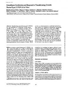
The obtained conversion and yield at different reaction temperatures is shown in Figure 3 for a total flow rate of 10.5 mL·min−1.
Molecules 2016, 21, 5
6 of 16
The obtained conversion and yield at different reaction temperatures is shown in Figure 3 for a Molecules 2016, 21, 0005 66 of Molecules 2016, 21,of 0005 of 15 15 total flow rate 10.5 mL¨ min´1 .
Figure 3: flow rate of Figure OMR, conversion conversion and and yield Figure 3. 3: OMR, OMR, conversion and yield of of TBPP TBPP synthesis, synthesis, 2nd 2nd reaction reaction step step at at aa total total flow flow rate rate of of −1 ´1 10.5 mL·min depending on the reaction temperature. 10.5 min−1 depending dependingon onthe thereaction reactiontemperature. temperature. 10.5 mL¨ mL·min −1. For that case only The same measurements were done total flow rate 18.5 mL·min The same same measurements measurementswere weredone doneatat ataaatotal totalflow flowrate rateofof of18.5 18.5mL¨ mL·min case only only The min´1−1.. For that case reaction temperatures of 25 and 40 were investigated (Figure 4). reactiontemperatures temperaturesof of25 25˝°C °C and 40 40 ˝°C °C were investigated investigated (Figure (Figure4). 4). reaction C and C were
Figure 4: conversion and yield of step at total flow rate of Figure 4. 4: OMR, OMR, conversion of TBPP TBPP synthesis, synthesis, 2nd 2nd reaction reaction step step at at aaa total total flow flow rate rate of of Figure OMR, conversion and and yield yield of TBPP synthesis, 2nd reaction −1 depending on the reaction temperature. 18.5 mL·min −1 ´1 18.5 mL·min depending on the reaction temperature. 18.5 mL¨ min depending on the reaction temperature.
In In all all cases, cases, aa positive positive influence influence of of increased increased reaction reaction temperature temperature on on the the process process performance performance is is In all cases, a positive influence of increased reaction temperature on the process performance seen. Processing at still higher reaction temperatures does not have a positive effect on the process seen. Processing at still higher reaction temperatures does not have a positive effect on the process is seen. Processing at still higher reaction temperatures does not have a positive effectwhich on the performance. performance. In In processing processing without without cooling cooling aa mean mean temperature temperature of of 81 81 °C °C is is observed observed which is is ˝ process performance. In processing without cooling a mean temperature ofconsisting 81 C is observed accompanied accompanied by by strong strong gas gas formation. formation. A A decomposition decomposition of of the the organic organic phase, phase, consisting mainly mainly of of which is accompanied by strong gas formation. A decomposition of the organic40phase, consisting TBPP TBPP is is observed observed by by Differential Differential Scanning Scanning Calorimetry Calorimetry at at temperatures temperatures above above 40 °C °C (heating (heating rate rate mainly of TBPP is observed by Differential Scanning Calorimetry at temperatures above 40 ˝ C −1 2.5 it is supposed that decomposition occurs under the abovementioned 2.5 K·min K·min−1)) [29]. [29]. Therefore Therefore it is supposed that decomposition occurs under the abovementioned (heating rate 2.5 K¨ min´1 ) [29]. Therefore it is supposed that decomposition occurs under the conditions. conditions. abovementioned conditions. Because Because the the second second reaction reaction is is aa biphasic biphasic one one and and the the acid acid halide halide can can accumulate accumulate within within the the Because the second reaction isquality a biphasic one anddirectly the acidinfluences halide can accumulate within the organic phase it is evident that the of emulsion the process performance. organic phase it is evident that the quality of emulsion directly influences the process performance. organic phase itcompare is evident that theemulsifying quality of emulsionwith directlyanother influences the process performance. One One concept concept to to compare different different emulsifying devices devices with one one another and and to to distinguish distinguish them them from from One concept to compare different emulsifying devices with one another and to distinguish them from one another in terms of their efficiency on droplet disruption is the concept of energy density one another in terms of their efficiency on droplet disruption is the concept of energy density [30,31]. [30,31]. one another in equations terms of their efficiency on droplet disruption is the conceptEof energy density [30,31]. −3 the The The following following equations give give the the relationship relationship between between the the energy energy density density Evv (J·m (J·m−3), ), the power power input input −1 3 −1 P (J·s ), the flow rate Q (m ·s ) and the pressure drop Δp (Pa). −1 3 −1 P (J·s ), the flow rate Q (m ·s ) and the pressure drop Δp (Pa).
Molecules 2016, 21, 5
7 of 16
The following equations give the relationship between the energy density Ev (J¨ m´3 ), the power input P (J¨ s´1 ), the flow rate Q (m3 ¨ s´1 ) and the pressure drop ∆p (Pa). Ev “
P
(1)
.
Q .
P “ ∆pQ
(2)
Ev “ ∆p
(3)
According to this theory the energy density at a flow rate of 10.5 mL¨ min´1 (Table 2) as well as for a total flow rate of 18.5 mL¨ min´1 (Table 3) is calculated for the varied reaction temperatures and the corresponding pressure drops. Table 2. Energy density at a total flow rate of 10.5 mL¨ min´1 by using the OMR for TBPP synthesis at different reaction temperatures. Entry Trct. /˝ C Qges /mL¨ min´1 ∆p/Pa 1 2 3 4
25 30 40 50
10.5 10.5 10.5 10.5
180,000 150,000 140,000 120,000
Ev /kJ¨ m´3 180 150 140 120
Conversion %
Yield %
TBHP
PivCl
TBPP
54 56 59 66
58 61 65 72
57 60 63 68
τsect. 2 /s τges /s 2.1 2.1 2.1 2.1
3.5 3.5 3.5 3.5
Table 3. Energy density at a total flow rate of 18.5 mL¨ min´1 by using the OMR for TBPP synthesis at different reaction temperatures. Entry Trct. /˝ C Qges /mL¨ min´1 ∆p/Pa 1 2
25 40
18.5 18.5
380,000 300,000
Ev /kJ¨ m´3 380 300
Conversion %
Yield %
TBHP
PivCl
TBPP
71 79
69 78
68 77
τsect. 2 /s τges /s 1.2 1.2
2 2
Looking at the reaction temperature of 25 ˝ C and that of 40 ˝ C, at which the two flow rates were applied, an increase in the yield of TBPP is observed by increasing the total flow rate, even though the residence time shortens by a factor of 0.57. This positive influence can be explained by an enhanced mixing efficiency indicated by an increase in energy density from 180 kJ¨ m´3 to 380 kJ¨ m´3 for the case at 25 ˝ C and from 140 kJ¨ m´3 to 300 kJ¨ m´3 at a reaction temperature of 40 ˝ C. Also temperature increase causes higher yield and conversion, even if energy density decreases due to a change in viscosity. These measurements indicate that the considered perester synthesis depends on the one hand on the reaction temperature and on the other hand strongly on the energy input. The last can be set in relation to the mixing performance of the reactor. The attempt to carry out the TBPEH synthesis with the OMR at BAM was restricted to a total flow rate of 5.25 mL¨ min´1 due to technical reasons. At 50 ˝ C a TBPEH yield of 28% was obtained, which is remarkable low. Experiments with varying flow rates for TBPP production at Fraunhofer ICT-IMM showed that not until 10 mL¨ min´1 a good emulsification was gained. As a result, only then a distinct increase in conversion and yield was found. Taking into account the lower reactivity of EHC compared to that of PivCl, this characteristic can be expected for TBPEH production too. Probably the reactor (number and distance of orifices) and the reaction parameters (flow rate and temperature) have to be adapted to the reaction rate of EHC to end up at an optimized process. 2.1.2. Split and Recombine Microreactor The specific attribute of the Split and Recombine (SAR) reactor is the structure of its reaction channel. This structure splits fluid streams and combines them in an alternating manner. This
Molecules 2016, 21, 5
8 of 16
%%
is repeated along the whole reaction channel, hence, a permanent droplet break-up occurs. As a result, the contact surface of the liquid/liquid phases is continuously renewed and the emulsification is enhanced. detailed description of the SAR reactor is given by Boškovi´c [32]. The channel Molecules 2016, 21,A 0005 8 of 15 Molecules 2016, 21, 0005 8 of 15 dimensions are 600 µm in width, 300 µm in height and 1.64 m in length. With the SAR reactor, the reaction step was carried out in mode. Information about the production of only the second reaction carried in continuous mode. Information about production the second second reaction stepstep waswas carried out out in continuous continuous mode. Information about thethe production of the intermediate is specified in Section 3.3. of the intermediate is specified in Section 3.3. the intermediate is specified in Section 3.3. The The conversion conversion of of the the carboxylic carboxylic acid acid chloride chloride and and the the yield yield of of the the produced produced peroxyester peroxyester at at −1 are ´ 1 several synthesis temperatures at a total flow rate of 0.3 mL·min shown in Figure 55 (TBPP) and temperatures at at aa total totalflow flowrate rateofof0.3 0.3mL·min mL¨ min shown in Figure 5 (TBPP) −1 are are several synthesis temperatures shown in Figure (TBPP) and in 66 (TBPEH). For production, the of as the yield the and in Figure 6 (TBPEH). ForTBPP the TBPP production, the conversion of PivCl asas the of yield in Figure Figure (TBPEH). For the the TBPP production, the conversion conversion of PivCl PivCl as well well aswell the as yield of the ˝ C, peroxyester is high. Temperature influence is slightly noticeable, at least between 10 °C, 20 °C and of the peroxyester is high. Temperature influence is slightly noticeable, at least between 10 peroxyester is high. Temperature influence is slightly noticeable, at least between 10 °C, 20 °C and ˝ C and 30 higher temperature causes to Further 20 30 ˝ C,the whereas higher temperature causesconversion a better conversion to the product. desired product. 30 °C, °C, whereas whereas the higherthe temperature causes aa better better conversion to the the desired desired product. Further temperature increase does aa positive influence. Absolute values are Further temperature doeshave not have a positive influence. Absolute values arehigher higherthan than the temperature increaseincrease does not not have positive influence. Absolute values are higher than the values of the OMR, whereby e.g., flow rates really different (OMR lowest corresponding e.g., flow rates areare really different (OMR lowest flowflow rate corresponding values valuesof ofthe theOMR, OMR,whereby whereby e.g., flow rates are really different (OMR lowest flow ´1 ). −1). rate mL·min 10.5 mL¨ −1). rate 10.5 10.5 min mL·min
100 100 90 90 80 80 70 70 60 60 50 50 40 40 30 30 20 20 10 10 0 0
90 90
Conversion Pivaloyl chloride Conversion Pivaloyl chloride Yield tert-Butyl peroxypivalate Yield tert-Butyl peroxypivalate 95 93 95 92 95 93 95 91 92 88 91 87 88 87
10 10
20 20
30 30 TMean/ °C TMean/ °C
90 90
40 40
93 93
91 91
50 50
%%
Figure 5. 5. SAR reactor, reactor, conversionand and yieldofofTBPP TBPP synthesis,2nd 2ndreaction reaction step a total flow rate Figure step at at a total flow rate of Figure 5. SAR SAR reactor,conversion conversion andyield yield of TBPPsynthesis, synthesis, 2nd reaction step at a total flow rate ´1−1depending of 0.3 mL·min depending on the reaction temperature. 0.3 mL¨ min on the reaction temperature. of 0.3 mL·min−1 depending on the reaction temperature. 100 100 90 90 80 80 70 70 60 60 50 50 40 40 30 30 20 20 10 10 0 0
Conversion 2-Ethylhexanoyl chloride Conversion 2-Ethylhexanoyl chloride Yield tert-Butyl peroxy-2-ethylhexanoate Yield tert-Butyl peroxy-2-ethylhexanoate 75 75 60 60
26 26
10 10
60 60
63 63
48 48
46 46
38 38
74 74
34 34
20 20
30 30 TMean/ °C TMean/ °C
40 40
50 50
Figure 6. SAR reactor, conversion and yield of TBPEH synthesis, 2nd reaction step at a total flow rate Figure 6. 6. SAR SAR reactor, reactor, conversion conversion and and yield yield of of TBPEH TBPEH synthesis, synthesis, 2nd 2nd reaction reaction step step at at aa total total flow flow rate rate Figure of 0.3 mL·min−1 depending on the reaction temperature. −1 ´1 of 0.3 0.3 mL¨ mL·min of min depending dependingon onthe thereaction reactiontemperature. temperature.
Comparing Comparing the the production production of of the the two two peroxyesters peroxyesters TBPP TBPP and and TBPEH TBPEH under under the the same same conditions conditions in the SAR reactor, the lower conversion of the long-chain acid chloride, 2-ethylhexanoyl in the SAR reactor, the lower conversion of the long-chain acid chloride, 2-ethylhexanoyl chloride chloride (EHC), and the corresponding lower yield of TBPEH is obvious. It is explained by a difference (EHC), and the corresponding lower yield of TBPEH is obvious. It is explained by a difference in in the the reactivity reactivity of of the the used used acid acid halides. halides. Pivaloyl Pivaloyl chloride chloride is is more more reactive reactive than than 2-ethylhexanoyl 2-ethylhexanoyl chloride. chloride. An increase in reaction temperature increases the yield of TBPEH too, e.g., at a reaction temperature
Molecules 2016, 21, 5
9 of 16
Comparing the production of the two peroxyesters TBPP and TBPEH under the same conditions in the SAR reactor, the lower conversion of the long-chain acid chloride, 2-ethylhexanoyl chloride (EHC), and the corresponding lower yield of TBPEH is obvious. It is explained by a difference in the reactivity of the used acid halides. Pivaloyl chloride is more reactive than 2-ethylhexanoyl chloride. Molecules 2016, 21, 0005 9 of 15 An increase in reaction temperature increases the yield of TBPEH too, e.g., at a reaction temperature ˝ C a yield of 26% is obtained, whereas at a reaction temperature of 50 ˝ C the yield of 63% of 10 10 °C of a yield of 26% is obtained, whereas at a reaction temperature of 50 °C the yield of 63% is is significantly higher. further increaseininreaction reactiontemperature temperaturedoes doesnot not necessarily necessarily enhance enhance the the significantly higher. AA further increase productivity. As As known known from from DSC DSC measurements, measurements, decomposition decomposition of of TBPEH TBPEH becomes becomes detectable detectable at at productivity. ˝ C [29] and counteracts a higher yield. about 60 about 60 °C [29] and counteracts a higher yield. As mentioned mentioned before, before, the the flow flow rates rates in in the the OMR OMR were were quite quite different different compared compared to to the the SAR SAR As reactor. Therefore, Therefore,additional additional runs in the reactor producing were carried outhigher with reactor. runs in the SARSAR reactor producing TBPPTBPP were carried out with ´1 , covering 1, 2, 3 and 4 mL¨ min´1 at a constant synthesis higher total flow rates than 0.3 mL¨ min total flow rates than 0.3 mL·min−1, covering 1, 2, 3 and 4 mL·min−1 at a constant synthesis temperature ˝ C. Figure 7 shows a decrease of conversion and yield at flow rates higher than temperature of 40 of 40 °C. Figure 7 shows a decrease of conversion and yield at flow rates higher than 1 mL·min−1. By ´ 1 1 mL¨ min . By increasing the the totalresidence flow rate time the residence time decreases, a better can be increasing the total flow rate decreases, but a better but mixing canmixing be assumed. ´1 and 3 mL¨ min´1 , the residence time decreases assumed. Looking at the flow rates of 0.3 mL¨ min Looking at the flow rates of 0.3 mL·min−1 and 3 mL·min−1, the residence time decreases by a factor of by afrom factor from 64 s TBPP to 6.4 production s, but TBPP is production is still at a high level. Bythe changing thefrom flow 10, 64ofs 10, to 6.4 s, but still at a high level. By changing flow rate ´1 to 3 mL¨ min´1 , the yield of TBPP decreases from 90% to 82%. In spite of this rate from 0.3 mL¨ min 0.3 mL·min−1 to 3 mL·min−1, the yield of TBPP decreases from 90% to 82%. In spite of this reduction 1 to 152,000 kg¨ m´3 ¨ h´1 . reduction the space-time yieldfrom increases from nearly 17,000 m´3 ¨ h´ −3·h−1 kg¨ −3·h−1. the space-time yield increases nearly 17,000 kg·m to 152,000 kg·m 100
92 90
90
Conversion Pivaloyl chloride Yield tert-Butyl peroxypivalate
92
89
85
82
80
80 82
82 82
3
4
70
%
60 50 40 30 20 10 0
0 0 0.3
1
2
Total flow rate/ mLmin
-1
Figure Figure 7. 7. SAR SARreactor, reactor, conversion conversion and and yield yield of of TBPP TBPP synthesis, synthesis, 2nd 2nd reaction reaction step step at at aa reaction reaction temperature of 40 °C in dependence on total flow rate. ˝ temperature of 40 C in dependence on total flow rate.
In the same way as described in Section 2.1.1., for the OMR measurements the energy density In the same way as described in Section 2.1.1, for the OMR measurements the energy density can be calculated for the TBPP synthesis using the SAR reactor at different flow rates (Table 4), while can be calculated for the TBPP synthesis using the SAR reactor at different flow rates (Table 4), while synthesis temperature is kept constant. synthesis temperature is kept constant. Table 4. Energy density at varying total flow rates by using the SAR reactor for TBPP synthesis at a Table 4. Energy density at varying total flow rates by using the SAR reactor for TBPP synthesis at a reaction temperature of 40 °C. reaction temperature of 40 ˝ C.
Entry Entry
1 12 23 3 4 4
Trct./°C Trct.
/˝ C
40 4040 4040 40 40 40
Qges/mL·min−1 Qges
/mL¨ min´1 1 2 3 4
1 2 3 4
Δp/Pa
∆p/Pa
124,226 146,917 124,226 146,917 174,491 174,491 205,021 205,021
Conversion % Yield % Ev/kJ·m−3 Conversion % Yield % PivCl TBPP ´3 Ev /kJ¨ m PivCl TBPP 124 92 89 147 124 9285 8982 147 8580 8282 174 174 80 82 205 82 82 205 82 82
τges/s τges /s
19.2 9.6 19.2 9.6 6.4 6.4 4.8 4.8
With increasing flow rate the energy density in the SAR reactor experiments is increasing as well, but in contrast to the OMR experiments these rises do not cause an increase in conversion and yield. On the contrary, the yield decreases at least when accelerating the total flow rate from 1 mL·min−1 to 2 mL·min−1. Further increase shows no effect, even though residence time decreases further. That may be an indication that at a certain level of conversion the provided residence time
Molecules 2016, 21, 5
10 of 16
With increasing flow rate the energy density in the SAR reactor experiments is increasing as well, but in contrast to the OMR experiments these rises do not cause an increase in conversion and yield. On the contrary, the yield decreases at least when accelerating the total flow rate from 1 mL¨ min´1 to 2 mL¨ min´1 . Further increase shows no effect, even though residence time decreases further. That may be an indication that at a certain level of conversion the provided residence time gets more important compared to an increase in energy density to enhance the mixing performance. A comparison of the OMR and SAR reactor is difficult because of complex interaction of flow rate Molecules 2016, 21, 0005 10 of 15 and residence time, pressure drop and energy density and the specific mixing structure. Hence, the specification of the is not sufficient for for a differentiation of different reactor types specification theenergy energydensity densityalone alone is not sufficient a differentiation of different reactor processing reactive species. types processing reactive species. 2.1.3. Capillary Capillary Tube Tube Reactor Reactor in in Combination Combination with with Ultrasonication Ultrasonication 2.1.3. The application application of of ultrasound ultrasound (US) (US) to to break-up break-up the the biphasic biphasic reaction reaction system system of of the the second second The reaction step is a completely different approach that can be used to enhance mixing performance. reaction step is a completely different approach that can be used to enhance mixing performance. Former runs runs without without this this specific specific kind kind of of reactant reactant stress stress showed showed aa low low conversion conversion of of acid acid chloride chloride Former ´ 1 and a synthesis and a low yield of the corresponding peroxyester, e.g., at a flow rate of 0.3 mL¨ min −1 and a low yield of the corresponding peroxyester, e.g., at a flow rate of 0.3 mL·min and a synthesis ˝ C the conversion of EHC is 61% and the yield of TBPEH is 57% [25]. That temperature of of 30 30 °C temperature the conversion of EHC is 61% and the yield of TBPEH is 57% [25]. That conversion and yield is improved by by ultrasonication ultrasonication is is shown shown in in Figure Figure 8, 8, covering covering aa temperature temperature conversion and yield is improved ˝ C to 40 ˝ C at a total flow rate of 0.3 mL¨ min´ 1 . In comparison to the results obtained range from 10 −1 range from 10 °C to 40 °C at a total flow rate of 0.3 mL·min . In comparison to the results obtained without US, US, aa significant significant increase increase in in yield yield up up to to 90% 90% of of TBPEH TBPEH is is obtained. without obtained. Conversion 2-Ethylhexanoyl chloride Yield tert-Butyl peroxy-2-ethylhexanoate 90 90
100 90
81
78
80
81
75
70
%
60
60
58
50 40 30 20 10 0
10
20
30
40
TMean/ °C
Figure tube reactor with ultrasonication, conversion andand yieldyield of TBPEH synthesis, 2nd Figure 8.8.Capillary Capillary tube reactor with ultrasonication, conversion of TBPEH synthesis, −1 depending ´1 reaction step at a total flow rate of 0.3 mL · min on the reaction temperature. 2nd reaction step at a total flow rate of 0.3 mL¨ min depending on the reaction temperature.
A temperature influence on conversion and yield is visible, as already observed in the runs of A temperature influence on conversion and yield is visible, as already observed in the runs of TBPEH production in the SAR reactor. Noticeable is the low numerical difference between TBPEH production in the SAR reactor. Noticeable is the low numerical difference between conversion conversion and yield, which corresponds to a high selectivity of peroxyester formation. With respect and yield, which corresponds to a high selectivity of peroxyester formation. With respect to the length to the length of the capillary tube, which was immersed in the ultrasonic bath (0.58 m of total tube of the capillary tube, which was immersed in the ultrasonic bath (0.58 m of total tube length), the best length), the best space-time-yield obtained is 12,500 kg·m−3·h−1. ´ 3 ´ 1 space-time-yield obtained is 12,500 kg¨ m ¨ h . A drawback of ultrasonication of liquids is the generation of bubbles, which can collapse A drawback of ultrasonication of liquids is the generation of bubbles, which can collapse producing a local pressure and temperature spot. Rivas et al. [33] reported the generation of producing a local pressure and temperature spot. Rivas et al. [33] reported the generation of microbubbles and light emission in a microstructured reactor, whereas only water, aqueous luminal microbubbles and light emission in a microstructured reactor, whereas only water, aqueous luminal or propanol was used. In case of liquid organic peroxides the flow through of bubbles (cavitated or propanol was used. In case of liquid organic peroxides the flow through of bubbles (cavitated systems) can be a potential risk for a reinforced decomposition behavior. Such systems can facilitate systems) can be a potential risk for a reinforced decomposition behavior. Such systems can facilitate the transition from a thermal decomposition via deflagration into a detonation, which is a more the transition from a thermal decomposition via deflagration into a detonation, which is a more energy-rich process with severe consequences compared to a thermal decomposition. Also induced detonations can be propagated better in cavitated liquid organic peroxides [34]. The specific compounds, technical pure TBPP and TBPEH, which are comparable to the organic phase of the reaction mixture, propagate a detonation if the liquid is tested in the cavitated state following UN-Test Series 1, Type 1(a), Appendix 3 [35]. Such tests are carried out to classify substances or
Molecules 2016, 21, 5
11 of 16
energy-rich process with severe consequences compared to a thermal decomposition. Also induced detonations can be propagated better in cavitated liquid organic peroxides [34]. The specific compounds, technical pure TBPP and TBPEH, which are comparable to the organic phase of the reaction mixture, propagate a detonation if the liquid is tested in the cavitated state following UN-Test Series 1, Type 1(a), Appendix 3 [35]. Such tests are carried out to classify substances or mixtures in connection with a safe transport, storage and handling according to international appointed test methods. The mentioned test run in tubes with an inner diameter of 50 mm, meaning an enlargement in diameter by a factor of 50 compared to the used capillary tube reactor. At the moment it is not known if the effect of cavitation on the decomposition behavior appears in small dimensioned tubes as well, in particular for the named compounds. Nevertheless, the above given results show the possibility of using US for this type of reaction, at least when done on a bench scale. 3. Experimental Section Because different laboratories were involved in this research, different chemical suppliers and analytical systems were used. Thus, the following sections distinguish between measurements at Fraunhofer ICT-IMM (OMR/TBPP) and BAM (Berlin, Germany, SAR, capillary tube/TBPP and TBPEH). 3.1. Test Procedure and Set-Up Using the Orifice Microreactor Using the OMR at Fraunhofer ICT-IMM both reaction steps are performed in consecutive manner. An aqueous solution of 22.7 w/w KOH and an aqueous solution of 68 w/w TBHP are feed with HPLC-pumps (K-501 with a 10 mL stainless steel pump head, Knauer, Berlin, Germany) into the OMR and contacted in a 300 µm caterpillar micromixer (Fraunhofer ICT-IMM) with twelve splitting and recombination sections. The feed rates are adjusted in such a way that the KOH is in a slight excess of 1.12 eq. based on the amount of TBHP. The reaction mixture is then fed into the second 300 µm caterpillar micromixer with twelve splitting and recombination sections and contacted with the PivCl. The substoichiometric amount of PivCl (0.85 eq.) is fed via a Knauer Smartline 1000 pump with a 10 mL titanium pump head. The reaction temperature is controlled by using a temperature controlled water bath connected to the OMR heat exchanger. The total flow rates used are 10.5 mL¨ min´1 and 18.5 mL¨ min´1 , leading to residence times for the second step of the reaction of 2.1 s and 1.2 s, respectively. 3.2. Test Procedure and Set-Up Using the Split and Recombine Reactor and a Capillary Tube Reactor Combined with Ultrasonication With both reactor types only the second reaction step was carried out continuously. The intermediate, the aqueous tert-butyl potassium peroxide solution (TBKP), was produced in semi-batch mode. As capillary tube a simple PFA tube with an inner diameter of 1 mm (outer diameter 1/16 inch) and a total length of 1.25 m was used. It was immersed in an ultrasonic bath (RK 156 BH, 35 Hz, Bandelin Electronic, Berlin, Germany), the effective tube length in the bath was 0.58 m. The SAR, made of glass, was purchased from Mikroglas Chemtech GmbH (Mainz, Germany). In case of the capillary tube reactor, the reactants were first mixed in a y-shaped mixer and then transferred into the PFA tubing where ultrasonication occurred. The SAR reactor, equipped with two inlets, was supplied directly with the reactants. Syringe pumps from Little Things Factory (Elsoff, Germany) were used for fluid supply. Individual flow rates of intermediate and acid chloride were adjusted for TBPEH synthesis in a ratio of 1 mol TBKP to 1 mol EHC. For TBPP synthesis molar ratio of TBKP to PivCl was 1.15:1. The total flow rate varied between 0.3 mL¨ min´1 and 4 mL¨ min´1 for the SAR reactor experiments, while only a flow rate of 0.3 mL¨ min´1 was used for the experiments in the capillary tube reactor with US. Prior to the reactant contact within the microreactor, both fluid streams were pre-heated/ pre-cooled in a bath, in which the reactor was immersed too. The bath temperature was regulated by a thermostat. The temperature varied between 10 ˝ C and 50 ˝ C in 10-K steps when the SAR reactor
Molecules 2016, 21, 5
12 of 16
was used and between 10 ˝ C and 40 ˝ C when the capillary tube was used as reactor. After leaving the SAR reactor or in case of the capillary tube, after leaving the ultrasonic bath, the reaction mixture was cooled down with a tube in tube heat exchanger to stop or at least to reduce further conversion on the way to the separation funnel. The last was already filled with approximately 100 mL deionized water to quench any still ongoing reaction. The organic and aqueous phases were separated. 3.3. Preparation of the Intermediate tert-Butyl Potassium Peroxide (TBKP) in Semi-Batch Mode The intermediate was synthesized in a stirred tank reactor. Aqueous KOH solution (22.7 w/w) was provided in the reactor, tempered to 25 ˝ C and converted with aqueous TBHP solution (68 w/w to 69 w/w) under nearly isothermic conditions. Concentration of TBKP in the intermediate solution was analyzed by iodometric redox titration. For the SAR reactor experiments the TBKP concentration was 31.1 w/w and for the experiments in the capillary tube reactor 31.8 w/w. 3.4. Chemicals KOH (puriss. p.a., Reag. Ph. >85%), TBHP (70 w/w in water) and PivCl (99% GC) were purchased from Sigma Aldrich (Munich, Germany). MeCN (Rotisolvr gradient grade) was purchased from Carl Roth GmbH & Co. (Karlsruhe, Germany) and TBPP (70 w/w–80 w/w in isododecane as analytical reference substance) was obtained from Pergan (Bocholt, Germany). KOH (puriss. p.a., Reag. Ph.) and acetonitrile (Rotisolv HPLC 99.9%) were purchased from Carl Roth GmbH & Co. HCl (1 N, Titrisol) was purchased from Merck KGaA (Darmstadt, Germany). For the measurements at BAM several aqueous TBHP solutions of a peroxide producer with a concentration of about 70 w/w were used. The exact concentration was analysed by iodometric redoxtitration before the TBHP was used as reactant in the first reaction step. Aqueous KOH solution (22.7 w/w) was prepared from solid KOH pellets, purchased from Merck KGaA. Its concentration was verified by acid-base titration. PivCl purum (ě98% GC) from Acros Organics (Geel, Belgium) and 2-ethylhexanoyl chloride (99% GC) from Merck KGaA were used respectively in the second step. 3.5. Analytical Part Reaction mixtures (organic and aqueous phase), produced with the OMR at Fraunhofer ICT-IMM were analysed via HPLC. At BAM, only the organic phase of the reaction mixture was analyzed via HPLC. Peroxide concentration in TBHP solution and intermediate (TBKP) was analysed by iodometric redoxtitration. Samples from the OMR experiments are pre-treated as follows: 1 g–1.5 g of reaction mixture is diluted with 20 mL of a 7:3 mixture of MeCN and water (adjusted to pH 2.5 with 1 N aqueous HCl) and then injected into the HPLC. The eluent consists of MeCN and water (pH 2.5 adjusted with 1 N aqueous HCl). The flow rate of 1 mL¨ min´1 results in a starting pressure of 15.2 MPa using a fluid gradient with following operation conditions: Pump B: t = 2 min (MeCN) 25%; Pump B: t = 5 min (MeCN) 70%; Pump B: t = 8 min (MeCN) 70%; Pump B: t = 10 min (MeCN) 25%; Controller stop: t = 18 min; oven temperature: 25 ˝ C. The reaction components are detected using a PDA detector at a wavelength of 230 nm; Cell temperature 40 ˝ C; slit width 1.2 nm; Lamp: D2. Shimadzu Deutschland GmbH (Duisburg, Germany) LC System: System Controller: CBM-20A, Pump A and B: LC-20AD, Auto sampler: SIL-20A HT, Column oven: CTO-20AC, PDA: SPD-M20A. The used reversed phase HPLC column is a 250 ˆ 4.0 mm Nucleosil 120C 18 5 µm (MZ-Analysentechnik, Mainz, Germany, Art. No. 250.4 0.3135.N, Ser. No. 15130818). At BAM, a sample of the organic phase of the reaction mixtures (15 µL) is taken and poured in a 10 mL graduated flask, diluted with 0.5 mL methyl alcohol for a better dissolution and finally filled up with the HPLC eluent. The eluent consists of a methyl alcohol and water mixture 55:45 w/w for TBPP samples and of 65:35 w/w for TBPEH samples. The eluent is buffered to pH 2.6 with a H3 PO4 solution (0.6 mL H3 PO4 /L eluent). During the entire analytical run on the Waters HPLC instrument (Pump: 510, Auto sampler: 717plus, Column oven: Jetstream plus, Absorbance detecector: 486,
Molecules 2016, 21, 5
13 of 16
Waters Cooperation, Milford, MA, USA, the eluent composition is kept constant, no gradient is applied. Injected sample volume is 10 µL. As separation column a reversed phase HPLC column (Kinetix 2.6u XB-C18 100Å, 00C-4496-E0, Phenomenex Inc., Torrance, CA, USA) with the dimensions 4.6 mm Id, 50 mm length, 2.6 µm particle size, 100 Å pore size is applied. Oven temperature is kept constant at 30 ˝ C. The UV detector is set to 207 nm in the first 2.1 min and afterwards to 220 nm. With a flow rate of 1 mL¨ min´1 retention times of analyzed components in the TBPP samples are 1.24 min for TBKP, 1.6 min for pivalic acid, 2.45 min for PivCl and 5.30 min for TBPP. For TBPEH samples retention times are as follows: 1.1 min for TBKP, 2.69 min for 2-ethylhexanoic acid, 5.06 min for EHC and 9.67 min for TBPEH. Iodometric redoxtitration of TBHP or TBKP is carried out with a Methrom AG (Zofingen, Switzerland) system (736 GP Titrino, Pt ring electrode). The peroxide reacts with a SO2 solution, added in molar excess. Back tritration of the non-reacted SO2 with iodine allows the calculation of the peroxide concentration. The titration beaker filled with 20 mL toluene and 40 mL methyl alcohol before a 0.1 N SO2 solution (prepared from Karl-Fischer solution A, 990 mL methyl alcohol and 90 mL pyridine) is added. The weighted sample is filled into the beaker. After a reaction time of a few minutes peroxide is converted and the remaining SO2 is titrated with 0.1 N iodine solution. Conversion is followed potentiometrically (automatic equivalence point finding monotonic titration, MET). In the same manner a blind sample is analyzed. 4. Conclusions With the application of the OMR, the SAR reactor and the capillary tube reactor in combination with US, three different mixing strategies were tested. In the OMR and in the SAR reactor, emulsification is achieved due to the static mixing elements that are implemented into the reaction channel. For the capillary tube reactor, mixing is induced by the stress that is applied by US. For the presented reaction, the synthesis of peroxyester from an aqueous solution of a precursor and an acid halide, the emulsification of the components plays an important role. An increase in mixing performance helps to shorten the reaction time down to seconds. It is known from conventional used orifices that an increase in flow rate leads to a higher turbulence in the fluid behind the orifice. This fact was observed also in the peroxyester production with the OMR. As a consequence, a high yield could be achieved at high flow rates and very short residence times. Under the best process conditions, a space-time-yield of 414,000 kg¨ m´3 ¨ h´1 is obtained. Such high values make microreaction technology very attractive for industrial applications. In the SAR reactor, the increase in total flow rate led only up to a certain value to an increase in conversion and yield. A further increase of flow rate caused a contrary trend, as conversion and yield decreased due to shorter residence time. The influence of reaction temperature on the reactor performance is clearly visible in all three discussed systems. This influence cannot directly be correlated to a special design criteria of any one of the investigated microreactors, because they differ in inner volume and mixing structure. Therefore, we tried to use the concept of energy density as one characteristic variable to compare the microreactor performances with each other. For the OMR and the SAR reactor the energy density, which is proportional to the pressure drop, was calculated for the TBPP synthesis. For certain synthesis parameters at least similar energy density values were obtained in both reactor types. Consideration of conversion and yield showed that the energy density as one single parameter is not a suitable characteristic variable to compare different microreactors. Due to the reactivity of the chemical system the influence of energy density on the reactor performance could not be fully decoupled from e.g., kinetic parameters of the investigated reactions. To overcome this effect, it is necessary to limit this multiparameter problem to e.g., a one parameter problem. It is therefore necessary to keep parameters like residence time, energy density, and reaction temperature constant for each type of microreactor. Furthermore, the produced interfacial area in case of the biphasic system, takes influence on the reaction performance. Thus, it has to be checked if all microreactors produce the same interfacial area by the same energy input. If that is the case, the influence of mass
Molecules 2016, 21, 5
14 of 16
transfer should be similar for all types of microreactors. For the capillary tube reactor the produced interfacial area should be set in correlation to the energy input by ultrasound. The capillary tube reactor with ultrasonication showed the best results concerning the conversion of EHC and the yield of TBPEH. Noticeable is the high selectivity for the TBPEH synthesis with this reactor type. A drawback of this set-up is the potential risk of severe decomposition of the peroxyester, initiated by the collapse of bubbles, which are produced in the liquid reaction mixture by ultrasonication. Such an occurrence was not observed during the test runs, but cannot be excluded. In general, several microstructured reactors are suitable for the production of TBPP and TBPEH, and high space-time yields can be achieved. Production of high quantities of peresters requires reasonable scale-up or numbering up of the microreactor. It is a challenge for process monitoring and control technology and also a question of quantity of reactor material. In the case of peroxide synthesis, used often in smaller amounts for the initiation of a polymerization process, a production on demand could be a promising solution. Acknowledgments: Tobias Illg thanks the Deutsche Bundesstiftung Umwelt (www.DBU.de) for granting the PhD scholarship (file number20007/894), as well as Volker Hessel, Jaap C. Schouten, Patrick Löb, for the supervision of the PhD thesis and Christian Hofmann for the construction of the OMR. Authors from BAM would like to thank R. Jungnickel from BAM for analytical assistance. Author Contributions: A. Knorr and L. Fritzsche conceived, designed and performed the experiments that are related to the SAR reactor as well as that for the capillary reactor in combination with ultrasonication. T. Illg conceived, designed and performed all the work that is related to the OMR. Conflicts of Interest: The authors declare no conflict of interest.
References 1.
2. 3. 4. 5. 6. 7. 8. 9. 10. 11. 12. 13. 14.
Dittmeyer, R.; Keim, W.; Kreysa, G.; Oberholz, A. Winnacker-Küchler-Chemische Technik. In Prozesse und Produkte, Band 3 Anorganische Grundstoffe, Zwischenprodukte; Wiley-VCH Verlag GmbH & Co. KGaA: Weinheim, Germany, 2005. Klenk, H.; Götz, P.; Siegmeier, R.; Mayr, W. Ullmanns Encyclopedia of Industrial Chemistry—Peroxy Compounds, Organic; Wiley-VCH Verlag GmbH & Co. KGaA: Weinheim, Germany, 2000. Sanchez, J.; Myers, T.N. Peroxides and Peroxide Compounds, Organic Peroxides. Kirk-Othmer Encycl. Chem. Technol. 2000. [CrossRef] Hordijk, A.; de Groot, J. Experimental data on the thermal kinetics of organic peroxides. Thermochim. Acta 1986, 101, 45–63. [CrossRef] Ho, T.; Duh, Y.; Chen, J.R. Case studies of incidents in runaway reactions and emerging relief. Process Saf. Prog. 1998, 17, 259–262. [CrossRef] Duh, Y.; Wu, X.H.; Kao, C. Hazard ratings for organic peroxides. Process Saf. Prog. 2008, 27, 89–99. [CrossRef] Roßmer, D.; Wobst, S. Verfahren zur Kontinuierlichen Herstellung von Perestern. DD128663 (A1), 30 November 1977. Winter, H.; Schmid, E. Verfahren zur Herstellung von Percarbonsaeure-tert.-butylestern. DE1518740 (B1), 29 June 1972. Kohn, P.M. Continuous peroxyester route to make its commercial debut. Chem. Eng. 1978, 7, 88–89. Milas, N.A.; Surgenor, D.M. Studies in organic peroxides IX. tert-butyl peroxyesters. J. Am. Chem. Soc. 1946, 68, 205–208. [CrossRef] Hessel, V.; Hardt, S.; Löwe, H. Chemical Micro-Process Engineering—Fundamentals, Modelling, and Reactions; Wiley-VCH: Weinheim, Germany, 2004. CoPIRIDE Project. Available online: http://www.copiride.eu/about_copiride.html (accessed on 22 July 2015). F3 Factory Project. Available online: http://www.f3factory.com/scripts/pages/en/home.php (accessed on 22 July 2015). POLYCAT Project. Available online: http://www.polycat-fp7.eu/about_copiride.html (accessed on 22 July 2015).
Molecules 2016, 21, 5
15. 16. 17. 18. 19. 20. 21.
22.
23. 24. 25. 26.
27.
28.
29. 30. 31. 32. 33.
34.
15 of 16
Chemie auf Rädern. Available online: http://corporate.evonik.de/de/produkte/product-stories/Pages /chemie-auf-raedern.aspx (accessed on 22 July 2015). INVITE Facility. Available online: http://www.invite-research.com/leistungen/leistungsportfolio.html (accessed on 22 July 2015). Azzawi, A.; Mehesch, H.E.; Zadow, E.; Frose, S.; Rhede, M. Method for the Production of Organic Peroxides by Means of a Microreaction Technique. WO2007042313 A3, 29 April 2007. Ebrahimi, F.; Kolehmainen, E.; Oinas, P.; Hietapelto, V.; Turunen, I. Production of unstable percarboxylic acids in a microstructured reactor. Chem. Eng. J. 2011, 167, 713–717. [CrossRef] Ebrahimi, F.; Kolehmainen, E.; Turunen, I. Safety Advantages of on-side microprocesses. Org. Proc. Res. Dev. 2009, 13, 965–969. [CrossRef] Wu, W.; Qian, G.; Zhou, X.G.; Yuan, W.K. Peroxidation of methyl ethyl ketone in a microchannel reactor. Chem. Eng. Sci. 2007, 62, 5127–5132. [CrossRef] Zhang, J.; Wu, W.; Qian, G.; Zhou, X.G. Continuous synthesis of methyl ethyl ketone peroxide in a microreaction system with concentrated hydrogen peroxide. J. Hazard. Mat. 2010, 181, 1024–1030. [CrossRef] [PubMed] Illg, T.; Hessel, V.; Löb, P.; Schouten, J.C. Continuous synthesis if tert-butyl peroxypivalate using a single-channel microreactor equipped with orifices as emulsification units. ChemSusChem 2011, 4, 392–398. [CrossRef] [PubMed] Illg, T.; Hessel, V.; Löb, P.; Schouten, J.C. Orifice microreactor for the production of an organic peroxide-non reactive and reactive characterization. Green Chem. 2012, 14, 1420–1433. [CrossRef] Illg, T. Novel Process Windows for the Safe and Continuous Synthesis of Tert-Butyl Peroxypivalate with Micro Process Technology; Technische Universität Eindhoven: Eindhoven, The Netherlands, 2013. Fritzsche, L.; Knorr, A. Transformation of the 2nd step of a peroxyester synthesis from semi-batch to continuous mode. Chem. Eng. Process. Process Intensif. 2013, 70, 217–221. [CrossRef] U.S. Chemical Safety and Hazard Investigation Board. Case Study: Fire and Explosion: Hazards of Benzoyl Peroxide; No. 2003-03-C-OH; U.S. Chemical Safety and Hazard Investigation Board: Washington, DC, USA, 2003. Kommission für Anlagensicherheit (KAS), TRAS 410 Erkennen und Beherrschen Exothermer Chemischer Reaktionen, Ermittlung der Gefahren, Bewertung und Zusätzliche Maßnahmen, Commission on Process Safety (Germany) Technical Rules on Installation Safety 410 Identification and Control of Exothermic Chemical Reactions, October 2012, Published in BAnz AT 20.12.2012, A Former Version (TAA-GS-05 Guide for the Identification and Control of Exothermic Chemical Reactions) is available in English. Available online: http://www.kas-bmu.de/publikationen/tras/TRAS_410_09102012.pdf (accessed on 17 December 2015). Knorr, A. Anwendung der TRAS 410 auf die Sicherheitstechnische Beurteilung Einer Perestersynthese (Application of the Technical Rule TRAS 410 to the Safety Evaluation of a Peroxide Synthesis). Ph.D. Thesis, Technische Universität Berlin, Berlin, Germany, January 2006. Fritzsche, L.; Knorr, A. Specification of the limit temperature Texo for a peroxide synthesis using different estimation methods. Chem. Eng. Trans. 2014, 36, 121–126. Karbstein, H.; Schubert, H. Developments in the continuous mechanical production of oil-water macro-emulsions. Chem. Eng. Process. 1995, 34, 205–211. [CrossRef] Stang, M.; Schuchmann, H.; Schubert, H. Emulsification in High-Pressure Homogenizers. Eng. Life Sci. 2001, 4, 151–157. [CrossRef] Boškovi´c, D.; Löbbecke, S.; Groß, A.; Köhler, M. Residence Time distribution studies in microfluidic mixing structures. Chem. Eng. Technol. 2011, 34, 361–370. [CrossRef] Rivas, D.F.; Ashokkumar, M.; Leong, T.; Yasui, K.; Tuziuti, T.; Kentish, S.; Lohse, D.; Gardeniers, H.J.G.E. Sonoluminescence and sonochemiluminescence from a microreactor. Ultrason. Sonochem. 2012, 19, 1252–1259. [CrossRef] [PubMed] Wandrey, P.-A.; Wehrstedt, K.-D. Sensitisation of liquid organic peroxides against detonation impact-an excessive or practice-orientated test method in Chemical Reactions. In Proceedings of the 35th Tutzing Symposium, Tutzing, Germany, 10–13 March 1997; Kreysa, G., Langer, O.-U., Pilz, V., Eds.; DECHEMA: Frankfurt am Main, Germany, 1997; pp. 133–146.
Molecules 2016, 21, 5
35.
16 of 16
UN Recommendations on the Transport of Dangerous Goods, Manual of Tests and Criteria, 5th ed.; United Nation: New York, NY, USA; Geneva, Switzerland, 2009.
Sample Availability: Samples are not available because storage of peroxide compounds is limited to a short time/ to a specific time period. They decompose continuously, even if stored at low temperatures. The original composition changes, concentration of peroxide degrades and byproducts may be produced. © 2015 by the authors; licensee MDPI, Basel, Switzerland. This article is an open access article distributed under the terms and conditions of the Creative Commons by Attribution (CC-BY) license (http://creativecommons.org/licenses/by/4.0/).