MICROSENSOR FOR LIQUID FLOW MEASUREMENTS ROBERTO JACOBE RODRIGUES AND ROGÉRIO FURLAN University of São Paulo, LSI / PSI / EPUSP Av.: Professor Luciano Gualberto, Trav.: 3 - no. : 158 Cidade Universitária – São Paulo – S.P. - CEP.: 05508-900 Corresponding author’s e-mail:
[email protected]
Abstract In this paper, a silicon thermal liquid flow microsensor is proposed. It consists on three freestanding microfilaments obtained through surface micromachining. The central one works as heater and the other two as temperature sensors symmetrically positioned to the heater, one upstream and one downstream. Results of numerical simulation of the microsensor obtained by using a commercial software package, are presented and compared to previous experimental results obtained for liquids in literature. This comparison shows a good qualitative agreement between numerical and experimental results.
1. Introduction There are many applications for flow microsensors with quick response, low power consumption, simple operation circuits and mass production low costs [1]. Also, there is a need for a flow sensor that can be used for different fluids and variable flow ranges [2]. The flow sensor has applications as in the field of liquid dosing [3] and process control [2] as well as in the microdomain studies, in the field of Micro-ElectroMechanical Systems (MEMS) [4]. A lot of gases and liquids flow sensors based on the thermal principle have been successfully presented in literature [2][5][6]. The sensor presented here is based on calorimetric principle, which uses the heat transfer from heated resistor to a flowing fluid. The difference between the temperatures on the sensors resistors symmetrically positioned to the heater, one upstream and one downstream, can be used to measure the fluid flow [2][5]. Figure 1 shows a schematic representation of the flow microsensor and correspondents temperature distributions. For zero flow, the upstream and downstream temperatures will be equal. However, when there is gas flowing, both upstream and downstream temperatures decrease as shown in Figure 1. The sensors resistors placed as arms of a Wheatstone bridge provide an output signal, which is proportional to the temperature difference between them [5][7]. With the results obtained by simulations, it is possible to achieve a better design optimization, to foresee possible experimental results and to explain possible device limitations [8][9][10].
Fig. 1: Schematic illustration of the flow microsensor based on the calorimetric principle analyzed in this work [7].
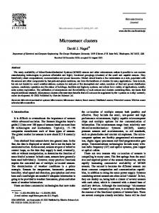
2. Liquid Flow Measurement Figure 2a shows, as an example, an experimental characteristic curve obtained by Lammerink et al [5] for water flow in the microchannel shown in Figure 2b. A flow channel of 1000 µm x 500 µm was used. For relative low flow velocities, the output signal changing is quick and at a certain flow, the output signal reaches a maximum and for higher flow velocities the signal is even lower. The output signal decrease is caused by a significant decrease of the heater temperature [5] on power constant mode [2][5]. The flow velocity, for which the output signal reaches a maximum value when gas is flowing, is significantly higher than one for liquids flow [5][7][9]. Thus, it is very important to control the heater power in the liquid flow sensors [2].
The heater resistor is formed by polysilicon and silicon nitride layers.
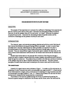
Fig. 4: Cross section of microbridge structure and tube used in the performed numerical simulations. a)
b) Fig. 2: Experimental results presented in literature [5]: a) characteristic curve for water flow and b) transversal view of the microchannel.
In order to improve the measurement range a feedback circuit can be used, as suggested in the literature, to control the heater resistor temperature [8]. This circuit is shown in Figure 3:
The water flow velocity was calculated for a tube with 3 mm of diameter and in a flow range of 0 to 0,1 m/s. To perform these water flow simulations, it was necessary to obtain the temperature dependence of the water physical properties. Thus, this temperature dependence was obtained by using linear regression and resulted in the equations given in Table 1: Physical Property Density (kg/m3)
Equation
(
Viscosity (kg/s) υ = 0,0018.e
Thermal Conductivity (W/m.K)
)
ρ = 1000 − 0 , 072 . T − 273 − 0 , 0035 .( T − 273 )
κ = 0,56.e
Specific Heat (J/kg.K)
2 2446. 1 − 1 +598992. 1 + 1 T 273 T 273
2 −309. 1 − 1 −111503. 1 − 1 T 273 T 273
4178,4
Table 1: Water physical properties as a function of the temperature.
A resistor, Rs, as arm of a Wheatstone Bridge is placed close to heater resistor, Rh, for thermal contact as shown in Figure 3. The heater power control signal is obtained from amplified Wheatstone bridge output, Vout. The applied signal on heater resistor is obtained through a current-voltage converter. When a pulsed signal is applied on the heater, a PWM circuit can be used to control the power.
3. Numerical Simulation for Liquid Flow Analysis The numerical simulations were performed using the software package ANSYS®/FLOTRAN® [11]. A two-dimensional model corresponding to the cross section through the sensor and channel system was used as shown in Figure 4. The heater with a width of 10 µm and a thickness of 0,8 µm is considered to be built on a silicon substrate with a width of 3 mm and a thickness of 300 µm. The heater-substrate distance is 0,7 µm.
14 Temperature Difference, ∆T
Fig. 3: Schematic diagram for heater power control on constant temperature mode.
Thus, a characteristic curve was obtained for water flow (Figure 5) and qualitatively compared to previous experimental results obtained for water flow presented in literature (Figure 2a) [5]. Notice that the output voltage, as presented in literature, is proportional to the difference between upstream and downstream temperatures, as obtained from numerical simulations. The characteristic curve, obtained from numerical simulations for heater to sensors distance of 120 µm, is shown in Figure 5:
12 10 8 6 4 2 0 0.00
0.01
0.02
0.03
0.04
0.05
Flow Velocity (m/s)
Fig. 5: Characteristic curve for water flow obtained from numerical simulation.
2
4. Discussion As shown in Figure 5, for flow velocities between 0 and around 0,015 m/s, there is a similar behavior with respect to previous experimental results in literature (see Figure 2a). For water flow velocities higher than around 0,015 m/s the numerical characteristic curve maintain the increase tendency because the heater temperature decrease was not considered. Thus, a study about heater dissipation must be performed to determine the decreasing rate of the heater temperature with the liquid flow velocity increase. To improve the measurement range, a feedback circuit can be designed, as suggested in the literature, to control the heater resistor temperature [8]. For example, a suggested circuit is shown in Figure 3. Dimensions differences, as tube diameter, heater to sensor distance and sensor surface, are the main cause of the difference between numerical and experimental flow range. The two-dimensional model used for the simulations as well as the assumed idealized boundary conditions are pointed in literature [5] as possible reasons of the deviations between calculated and measured results. In the liquid flow sensor, care must be taken with the stiction during the surface micromachining or during the water flow, due to enhance in the adhesion forces between fabricated structures and the substrate [12]. Thus, the increase in the distance between the suspended structures and the substrate is suggested as a possible solution.
5. Conclusions A silicon calorimetric liquid flow microsensor was proposed. Results of numerical simulation performed were presented and compared with previous experimental results obtained for liquids and gases in literature. This comparison showed a good qualitative agreement. The numerical results presented in this text will, in future, be compared with the experimental results, which will be obtained after the circuitry design and microsensor fabrication.
Acknowledgements We would like to acknowledge the financial support of FAPESP, providing a scholarship, and CNPq, and PADCT.
References: [1] T. Neda, K. Nakamura and T. Takumi, “A polysilicon flow sensor for gas flow meters” Sensors and Actuators Physical, issue 54, pages 626-631, 1996. [2] N.T. Nguyen, “Micromachined flow sensors – Review” Flow Measurements Instrumentation, Vol.8, No.1, pp. 7– 16, 1997. [3] M. Richter, P. Woias and D. Weiβ, “Microchannels for applications in liquid dosing and flow-rate measurement” Sensors and Actuators Physical, issue 62, pages 480-483, 1997.
[4] Xinxin Li, Wing Yin Lee, Man Wong and Yitshak Zohar, “Gas flow in constriction microdevices” Sensors and Actuators Physical, issue 83, pages 277-283, 2000. [5] T. S. J. Lammerink, N. R. Tas, M. Elwenspoek and J. H. J. Fluitman, “Micro – liquid flow sensor” Sensors and Actuators Physical, issue 37 - 38, pages 45-50, 1993. [6] G. Bedö, H. Fannasch and R. Müller, “A silicon flow sensor for gases and liquids using AC measurements” Sensors and Actuators Physical, issue 85, pages 124-132, 2000. [7] R. J. Rodrigues and R. Furlan, “Development of a Flow Microsensor Built on Silicon” Proceedings of the XIV International Conference on Microelectronics and Packaging, Campinas, August 1999. [8] E. Yoon, “An Integrated Mass Flow Sensor with On-Chip CMOS Interface Circuitry” Ph.D Thesis, University of Michigan, 1990. [9] L. Qio, S. Hein, E. Obermeier and A. Schubert, “Micro gasflow with integrated heat sink and flow guide” Sensors and Actuators A54, pp. 547-551, 1996. [10] Linan Jiang, Yuelin Wang, Man Wong and Yitshak Zohar, “Micro-Channels with Suspended Temperature Sensors for Heat Transfer Study” MEMS-Vol. 1, p. 567-573, 1999. [11] ANSYS: Technical Overview and User’s Manual, Procedures, v.1, 1994. [12] N. Tas, T. Sonnenberg, H. Jansen, R. Legtenberg and M. Elwenspoek, “Stiction in surface micromachining” Journal of Micromechanics, pp. 385-397, Aug. 1996.