metals Article
Microstructure and Oxidation Behavior of CrAl Laser-Coated Zircaloy-4 Alloy Jeong-Min Kim 1, *, Tae-Hyung Ha 1 , Il-Hyun Kim 2 and Hyun-Gil Kim 2 1 2
*
Department of Advanced Materials Engineering, Hanbat National University, 125 Dongseo-daero, Yuseong-gu, Daejeon 34158, Korea;
[email protected] Light Water Reactor Fuel Technology Division, Korea Atomic Energy Research Institute, 989-111 Daedek-daero, Yuseong-gu, Daejeon 34057, Korea;
[email protected] (I.-H.K.);
[email protected] (H.-G.K.) Correspondence:
[email protected]; Tel.: +82-42-821-1235
Academic Editor: Hugo F. Lopez Received: 24 October 2016; Accepted: 10 February 2017; Published: 15 February 2017
Abstract: Laser coating of a CrAl layer on Zircaloy-4 alloy was carried out for the surface protection of the Zr substrate at high temperatures, and its microstructural and thermal stability were investigated. Significant mixing of CrAl coating metal with the Zr substrate occurred during the laser surface treatment, and a rapidly solidified microstructure was obtained. A considerable degree of diffusion of solute atoms and some intermetallic compounds were observed to occur when the coated specimen was heated at a high temperature. Oxidation appears to proceed more preferentially at Zr-rich region than Cr-rich region, and the incorporation of Zr into the CrAl coating layer deteriorates the oxidation resistance because of the formation of thermally unstable Zr oxides. Keywords: laser coating; Zircaloy-4; CrAl; microstructure; oxidation
1. Introduction Zirconium alloys have been widely used as nuclear materials because of their high chemical stability under the normal operating conditions of a pressurized or boiling water reactor, low absorption cross-section of thermal neutrons, and fairly good mechanical properties. However, Zr alloys are vulnerable to the high temperature oxidation that can occur in the case of accidents. Since explosive hydrogen is formed by the rapid zirconium oxidation, a reduced oxidation rate of Zr alloys at high temperatures is necessary to improve the accident tolerance [1–4]. As a short-term solution to the problem, protective coating through an efficient and economical method such as laser coating and thermal spray can be considered [2,4]. It has been previously reported that a laser coating of chromium on Zircaloy-4 cladding tube could enhance the high-temperature oxidation resistance significantly [2]. The diffusion of oxygen into the Zr substrate was observed to be effectively restricted by the Cr coating layer during the oxidation. When a coated alloy is exposed to a high temperature, a significant diffusion and microstructural variation may occur at the coating/substrate interface, even for a short time. In the case of laser-treated FeCrAl-coating on Mo alloy, an interfacial reaction was found to occur at high temperature [5]. Meanwhile, it was reported that Cr–Al composite coatings were very effective in enhancing the oxidation resistance of metals at high temperatures [6]. Since Al2 O3 and Cr2 O3 can form on the surface of Cr–Al coated alloys, the high temperature oxidation resistance is expected to increase even further. Although the superiority of Cr–Al laser coating has already been demonstrated, research on the stability of the microstructure at high temperature is not yet sufficient. In the case of Cr-coated Zr alloy, comparatively a few phases can be formed between Cr coating layer and Zr substrate according to the Zr–Cr binary phase diagram [7]. However, in the case of CrAl-coated Zr alloy, more complicated Metals 2017, 7, 59; doi:10.3390/met7020059
www.mdpi.com/journal/metals
Metals 2017, 7, 59
2 of 8
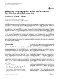
Cr-coated Zr alloy, comparatively a few phases can be formed between Cr coating layer and Zr substrate according to the Zr–Cr binary phase diagram [7]. However, in the case of CrAl-coated Zr Metals 2017, 7, 59 2 of 7 alloy, more complicated interfacial reactions would occur during the solidification and when it is exposed to high temperatures. Therefore, in the present research, CrAl laser-coated Zr alloys were exposed toreactions high temperatures, thenthe their microstructural variation and oxidation were interfacial would occurand during solidification and when it is exposed to highbehavior temperatures. investigated. Therefore, in the present research, CrAl laser-coated Zr alloys were exposed to high temperatures, and then their microstructural variation and oxidation behavior were investigated. 2. Materials and Methods 2. Materials and Methods Zircaloy-4 alloy (Zr-1.38%Sn-0.2%Fe-0.1%Cr, wt. %) sheets were used as the substrate, and (Zr-1.38%Sn-0.2%Fe-0.1%Cr, %) sheets substrate, andon CrAl CrAlZircaloy-4 (30 wt. % alloy Al) coating layer with the averagewt. thickness of were aboutused 300 as μmthe was deposited the (30 wt. % layer with the average thickness of about 300 µm was on the surface surface ofAl) thecoating Zr alloy through a laser coating process. A photograph of deposited the laser equipment for of the Zr alloy through a laser coating process. A photograph of the laser equipment for coating is coating is shown in Figure 1. The laser coating was carried out by using a continuous wave (CW) shown in Figure 1. The laser coating out bypower using of a continuous wave (CW) diode diode laser (wavelength of 1062 nm) was withcarried a maximum 300 W (PF-1500F model; HBLlaser Co., (wavelength of 1062 with asupply maximum power of 300 W (PF-1500F model; HBL Co.,Korea). Daejeon,Coating Korea) Daejeon, Korea) andnm) a power (Pwp14Y04K model; Yesystem Co., Daejeon, and a power supply (Pwp14Y04K model; Yesystem Co., Daejeon, Korea). Coating process variables such as laser power, powder injection speed, specimen moving process velocity,variables and gas such laserwere power, powder injection speed, specimen moving velocity, and gas flowfor speed flow as speed adjusted based on previous research results [8]. The applied power the were laser adjusted based on previous research results [8]. The applied power for the laser treatment ranged up treatment ranged up to 300 W, and the scanning speed was 14 mm/s. To prevent any oxidation to 300 W, and the scanning speed was 14 mm/s. To prevent any oxidation during the process, an inert during the process, an inert gas (Ar) was continuously blowing into the melted surface of specimen. gas was blowing into the surfacefor of coating specimen. mean size of the CrAl The (Ar) mean sizecontinuously of the CrAl alloy powders as amelted raw material wasThe 90 μm. alloyAs powders as a raw material for coating was 90 µm. previously mentioned, when used for nuclear fuel claddings or the like, it can be accidently As previously mentioned, when nuclear claddings that or the like, it can be accidently exposed to a high temperature for a used long for time, and itfuel is presumed the atmosphere is mainly exposed to a high for a long time, and itmicrostructural is presumed thatvariations the atmosphere is mainly water water vapor. Fortemperature ease of experiment, firstly, of the laser-coated vapor. For ease of experiment, firstly, microstructural variations of the laser-coated specimens were specimens were investigated under argon or air atmosphere at 1100 °C for different holding times. ◦ investigated under air atmosphere 1100 was C for different in holding times. Then, oxidation Then, oxidation testargon of theorCrAl and CrAlZratalloys conducted the steam atmosphere at 1200test °C ◦ C for 1 h. Cr-30 wt. % Al of the CrAl and CrAlZr alloys was conducted in the steam atmosphere at 1200 for 1 h. Cr-30 wt. % Al and Cr-30 wt. % Al-20 wt. % Zr alloy specimens were prepared through and Cr-30arc wt.remelting % Al-20 wt. % Zrto alloy specimens were prepared through vacuum arc remelting process vacuum process directly investigate the characteristics of the coating layers without to investigate the characteristics of the coating layers Zr substrate. Microstructural Zr directly substrate. Microstructural analyses were performed usingwithout SEM (JEOL, Tokyo, Japan) equipped analyses were performed using SEM (JEOL, Tokyo, Japan) equipped with an energy dispersive with an energy dispersive X-ray spectrometer (EDS, JEOL, Tokyo, Japan), and an X-ray spectrometer JEOL, Tokyo, Japan), and an X-ray diffractometer (XRD, Rigaku, Tokyo, Japan). diffractometer(EDS, (XRD, Rigaku, Tokyo, Japan).
Figure 1. Appearance of the laser equipment for coating. Figure 1. Appearance of the laser equipment for coating.
3. Results and Discussion 3.1. Micorstucture of CrAl Laser-Coated Zr Alloy Figure 2 shows SEM micrographs of CrAl laser coating layers on Zircaloy-4 alloy. Some Zr content could be measured in the CrAl coating layer that is far away from the Zr substrate (sometimes even near the coating surface), implying that significant intermixing of CrAl coating and Zr substrate
3. Results and Discussion 3.1. Micorstucture of CrAl Laser-Coated Zr Alloy 2 MetalsFigure 2017, 7, 59
shows SEM micrographs of CrAl laser coating layers on Zircaloy-4 alloy. Some3 ofZr7 content could be measured in the CrAl coating layer that is far away from the Zr substrate (sometimes even near the coating surface), implying that significant intermixing of CrAl coating and occurred during the laser coating. light bottomThe arealight is Zrbottom substrate, and content is increased Zr substrate occurred during theThe laser coating. area is the Zr Zr substrate, and the Zr as distance from the substrate is increased. A Zr-rich region appears between the Zr substrate and the content is increased as distance from the substrate is increased. A Zr-rich region appears between CrAl coating layer.and The the composition of thelayer. Zr-richThe partcomposition indicates the of formation of a solid Cr the Zr substrate CrAl coating the Zr-rich part solution indicatesofthe and Al in Zr. As indicated in Figure 2b, the majority of the Cr-rich coating layer is composed of two formation of a solid solution of Cr and Al in Zr. As indicated in Figure 2b, the majority of the Cr-rich rapidly regions: Cr-rich and AlZr(Cr) phases. coating solidified layer is composed of two rapidly solidified regions: Cr-rich and AlZr(Cr) phases.
Figure 2. 2. SEM-EDS (scanning electron microscopy–energy dispersive X-ray spectrometry) spectrometry) analysis analysis results of CrAl laser-coated Zircaloy-4 substrate alloy: (a) near the Zr substrate; (b) Cr-rich coating layer. results of CrAl laser-coated Zircaloy-4 substrate alloy: (a) near the Zr substrate; (b) Cr-rich coating
layer.
If the mixture of CrAl coating powders and the top surface of substrate were completely melted If the mixture primary of CrAl coating powders and the top surface of substrate were melted and homogeneous, Cr phase would be formed first from the liquid, since thecompletely major component and homogeneous, primary Cr phase would be formed first from the liquid, since the major of the surface liquid pool was Cr. Normal solidification reactions to form phases for Cr-30 wt. % component of the surface liquid pool was Cr. Normal solidification reactions to form phases for Al-20 wt. % Zr alloy (approximate chemical composition for the majority of the Cr-rich coating layer) Cr-30 wt. by % Al-20 wt. % Zr alloy (approximate composition for the majority of the Cr-rich predicted Pandat thermo-calculation programchemical are as follows [9]: coating layer) predicted by Pandat thermo-calculation program are as follows [9]: 1. Liquid → Cr at 1492–1283 ◦ C 1. Liquid → Cr at 1492–1283 °C 2. Liquid → Cr + Al2 Zr at 1283–1255 ◦ C 2. Liquid → Cr + Al2Zr at 1283–1255 °C ◦C 3. Liquid ++ Al Al22Zr Zr→ →Cr Cr++Al Al3Zr 1255°C 3 Zratat1255 3. Liquid ◦C 4. Liquid → → Cr Cr ++ Al Al33Zr Zrat at1255–1238 1255–1238°C 4. Liquid ◦C 5. Liquid → → Cr Zr ++ Al Al88Cr Cr55atat1238 1238°C 5. Liquid Cr ++ Al Al33Zr
and the the Cr Cr ++ AlZr AlZr eutectics eutectics should should have have formed formed upon upon solidification, solidification, however. however. The Cr dendrites and micrograph of the Cr-rich coating layer in Figure 2b reveals a somewhat different microstructure. microstructure. Namely,dendritic dendriticprimary primaryCrCrand and AlCr phases were observed. Additionally, incase the of case the Namely, AlCr phases were notnot observed. Additionally, in the theofAlZr AlZr phase, it shows a dendritic morphology. This discrepancy to be the because theoccurred growth phase, it shows a dendritic morphology. This discrepancy seems toseems be because growth occurred under a rapid solidification [10]. under a rapid solidification condition condition [10]. 3.2. CrAl Laser-Coated Zr Alloy that Exposed to a High Temperature Temperature Since the Zr Zr alloy is aimed to be to resistant at high at temperatures, the coatedthe specimen theCrAl-coated CrAl-coated alloy is aimed be resistant high temperatures, coated ◦ was isothermally heated in inert atmosphere at 1100 C for Figure times. 3 indicates that3 specimen was isothermally heated in inert atmosphere at different 1100 °C times. for different Figure inter-diffusion among phasesamong in the phases coatingin layers apparently afteroccurred 2 h. Theafter diffusion of indicates that inter-diffusion the coating layersoccurred apparently 2 h. The aluminum to beappears significant that the aluminum can be detected Zr substrate. diffusion ofappears aluminum to besosignificant so that thecontent aluminum content caninbethe detected in the Generally, three distinct parts are shown: Zr-substrate, Zr-rich area, Cr-rich area (the majority of the coating layer). An intermediate area between the Zr-rich and Cr-rich area may be counted, but it was excluded as it can be regarded as a part of the Zr-rich area.
Metals 2017, 7, 59
Zr substrate. Metals 2017, 7, 59
4 of 8
Generally, three distinct parts are shown: Zr-substrate, Zr-rich area, Cr-rich area (the 4 of 8
Metalsmajority 2017, 7, 59of the coating layer). An intermediate area between the Zr-rich and Cr-rich area may be 4 of 7
Zrcounted, substrate. three as distinct parts are shown: Zr-substrate, Zr-rich butGenerally, it was excluded it can be regarded as a part of the Zr-rich area.area, Cr-rich area (the majority of the coating layer). An intermediate area between the Zr-rich and Cr-rich area may be counted, but it was excluded as it can be regarded as a part of the Zr-rich area.
Figure 3. SEM-EDS analyses of laser-coated Zircaloy-4 substrate alloy after the isothermal heating at
Figure 3. SEM-EDS analyses of laser-coated Zircaloy-4 substrate alloy after the isothermal heating at 1100 °C for 2 h in inert atmosphere: (a) bright image; (b) backscattered image. 1100 ◦ C for 2 h in inert atmosphere: (a) bright image; (b) backscattered image. Figure 3. SEM-EDS analyses of laser-coated Zircaloy-4 substrate alloy after the isothermal heating at As indicated in Figure 4, the isothermal heating clarified that the microstructure of the Zr-rich 1100 °C for 2 h in inert atmosphere: (a) bright image; (b) backscattered image.
region near theinsubstrate composed of two regions: Zr-rich that and Cr-rich. The Zr-rich area is Zr As indicated Figure 4,isthe isothermal heating clarified the microstructure of the Zr-rich phase, and the Cr-rich area is postulated to be CrZr plus AlZr phases. Figure 5 also shows that thephase, region near the substrate is composed of two regions: Zr-rich and Cr-rich. The Zr-rich area is Zr As indicated in Figure 4, the isothermal heating clarified that the microstructure of the Zr-rich Cr-rich area area is composed of threetodistinct phases. The main phaseFigure is Cr, containing aboutthat 40 at. % Cr-rich Al andregion the Cr-rich is postulated be CrZr plus AlZr phases. 5 also the near the substrate is composed of two regions: Zr-rich and Cr-rich. Theshows Zr-rich area is Zr that is near the maximum solubility limit for Cr at 1100 °C. Others are Al-rich phases that include areaphase, is composed of threearea distinct phases. to The phase is Cr, containing 40 at. % Althe that is and the Cr-rich is postulated be main CrZr plus AlZr phases. Figure about 5 also shows that relatively large or very limited Zr content. According to the Pandat prediction and literature nearCr-rich the maximum solubility Cr atphases. 1100 ◦The C. Others are Al-rich phases that include area is composed of limit three for distinct main phase is Cr, containing about 40 at.relatively % Al [9,11,12], the Al-rich phases with large Zr contents seem to be Al3Zr. Meanwhile, the Al-rich phase that near the maximum solubility limit to forthe CrPandat at 1100 prediction °C. Others and are Al-rich phases that include large or is very limited Zr content. According literature [9,11,12], the Al-rich with a very low Zr content should be Al8Cr5. The microstructure of the coated specimens relatively large or very limited Zr content. According to the Pandat prediction and literature phases with largeheated Zr contents to be Al3 Zr. Meanwhile, thecoated Al-rich phase with a veryfor low Zr isothermally for 10 h seem was also investigated. However, the specimens maintained [9,11,12], thebe Al-rich phases with large Zr contents seem tospecimens be Al3Zr. Meanwhile, the Al-rich phase content should Al Cr . The microstructure of the coated isothermally heated for 10 8 5microstructural characteristics to those of specimens held for 2 h. It is believedh was 10 h showed similar with a very low Zr content should be Al8Cr5maintained . The microstructure of thesimilar coatedmicrostructural specimens also investigated. However, forinto 10 hnear showed that the microstructure ofthe thecoated coatingspecimens layer could be converted the equilibrium structure isothermally heated for 10 h was also investigated. However, the coated specimens maintained for even with atoholding time of just 2 h,held sincefor 1100 °CItisisa very high that temperature. characteristics those of specimens 2 h. believed the microstructure of the coating 10 h showed similar microstructural characteristics to those of specimens held for 2 h. It is believed layer could be converted into near the equilibrium structure even with a holding time of just 2 h, since that the microstructure of the coating layer could be converted into near the equilibrium structure ◦ C is a very high temperature. 1100even with a holding time of just 2 h, since 1100 °C is a very high temperature.
Figure 4. SEM-EDS analyses of Zr-rich area of CrAl-coated Zircaloy-4 alloy after the isothermal heating at 1100 °C for 2 h in inert atmosphere.
Figure 4. SEM-EDS analyses of Zr-rich of CrAl-coated Zircaloy-4 alloy the isothermal Figure 4. SEM-EDS analyses of Zr-rich areaarea of CrAl-coated Zircaloy-4 alloy afterafter the isothermal heating heating at 1100 °C for 2 h in inert atmosphere. ◦ Metals 2017,C7,for 59 2 h in inert atmosphere. 5 of 8 at 1100
Figure 5. SEM-EDS analyses CrAlcoating coating layer layer on thethe isothermal heating at at Figure 5. SEM-EDS analyses ofofCrAl on Zircaloy-4 Zircaloy-4alloy alloyafter after isothermal heating ◦ C for °C for in inert atmosphere. 11001100 2 h 2inh inert atmosphere.
The chemical composition distribution as a function of depth for the CrAl-coated specimen exposed to a high temperature air is shown in Figure 6. Like Figure 3, three distinct parts are generally observed in the specimen, and it is clear that oxidation proceeded a little, only at the surface. If cracks are formed in the coating layer, they are undoubtedly undesirable, because the protective coating may be detached from the substrate. Vertically-formed cracks are supposed to be
Metals 2017, 7, 59
Figure 5. SEM-EDS analyses of CrAl coating layer on Zircaloy-4 alloy after the isothermal heating at 1100 °C for 2 h in inert atmosphere.
5 of 7
The chemical composition distribution as a function of depth for the CrAl-coated specimen Thetochemical composition as a function of depth for the CrAl-coated exposed a high temperature airdistribution is shown in Figure 6. Like Figure 3, three distinct parts are specimen generally exposed to a high temperature air is shown in Figure 6. Like Figure 3, three distinct are observed in the specimen, and it is clear that oxidation proceeded a little, only at the surface.parts If cracks generally observed in the specimen, and it is clear that oxidation proceeded a little, only at the are formed in the coating layer, they are undoubtedly undesirable, because the protective coating surface. If cracks are formed in the coating layer, they are undoubtedly undesirable, because the may be detached from the substrate. Vertically-formed cracks are supposed to be more detrimental protective coating may since be detached the substrate. Vertically-formed cracks be to oxidation resistance, oxygenfrom ions can move easily through the cracks intoare thesupposed substrate.toThe more detrimental to oxidation resistance, since oxygen ions can move easily through the cracks into formation of Zr oxides was observed on the Zr substrate near a vertical crack, as shown in Figure 7. the substrate. The formation of content Zr oxides was observedonly on the Zr top substrate near a vertical crack, as However, a significant oxygen was measured at the surface of CrAl coating layer shown in Figure 7. However, a significant oxygen content was measured only at the top surface of in the sound region, and this suggests that the CrAl coating layer was effective in delaying the high CrAl coating layer in the sound region, and this suggests that the CrAl coating layer was effective in temperature oxidation. It also appears that Al and Zr oxidize more preferentially than Cr in the delayinglayer. the high temperature also thatagainst Al andoxidation Zr oxidizetoward more preferentially coating Unlike Al oxides,oxidation. Zr oxides It are notappears protective the matrix at than Cr in the coating layer. Unlike Al oxides, Zr oxides are not protective against oxidation toward high temperatures [1,2]. Therefore, a mixing between CrAl coating layer and Zr substrate should be the matrix at high temperatures [1,2]. Therefore, a mixing between CrAl coating layer and Zr carefully controlled to minimize the Zr content at the top of the surface coating layer. substrate should be carefully controlled to minimize the Zr content at the top of the surface coating layer.
Figure 6. SEM micrographs with EDS profiles of the oxidized CrAl coating layer on Zircaloy-4 after isothermal heating at 1100 C for 10 min in air. isothermal heating at 1100 °C for 10 min in air.
with EDS profiles of the oxidized CrAl coating layer on Zircaloy-4 after 6 of 8 Metals Figure 2017, 7, 6. 59 SEM micrographs ◦
Figure 7. 7. SEM-EDS SEM-EDS analyses analyses of of laser laser coated coated Zircaloy-4 Zircaloy-4 substrate substrate alloy alloy after after isothermal isothermal heating heating at Figure ◦ C for 30 min in air: (a) near the substrate; (b) top surface of the coating layer. 1100 1100 °C for 30 min in air: (a) near the substrate; (b) top surface of the coating layer.
Oxidation Behavior of CrAl Laser-Coated Zr Alloy at High Temperature Temperature 3.3. Oxidation the oxidation resistance of CrAl coating with that of the Zr-incorporated To clearly clearlycompare compare the oxidation resistance of CrAllayer coating layer with that of the CrAl layer, Cr-30CrAl wt. layer, % Al and Cr-30 Al-20 wt. wt. % Zr fabricated Zr-incorporated Cr-30 wt. wt. % Al%and Cr-30 % alloy Al-20cast wt. specimens % Zr alloy were cast specimens ◦ by vacuum arc remelting, and oxidationand test an in steam at 1200 C for 1 h at was carried out. the were fabricated by vacuum arcanremelting, oxidation test in steam 1200 °C for 1 hInwas carried out. In the case of accident, the temperature for nuclear cladding can be extremely increased, and is expected to be still under steam atmosphere. The corrosion resistance under atmosphere containing moisture can be quite different from that under dry air. Although Si and SiO2 are highly corrosion-resistant materials, they were quickly dissolved in a pressurized water condition at 360 °C in 18.9 MPa [2]. As shown in Figure 8, the coating layer without Zr possesses remarkably
Figure 7. SEM-EDS analyses of laser coated Zircaloy-4 substrate alloy after isothermal heating at 1100 °C for 30 min in air: (a) near the substrate; (b) top surface of the coating layer.
3.3. Oxidation Behavior of CrAl Laser-Coated Zr Alloy at High Temperature Metals 2017, 59 To 7, clearly
7 compare the oxidation resistance of CrAl coating layer with that of6 ofthe Zr-incorporated CrAl layer, Cr-30 wt. % Al and Cr-30 wt. % Al-20 wt. % Zr alloy cast specimens were fabricated by vacuum arc remelting, and an oxidation test in steam at 1200 °C for 1 h was case of accident, the temperature for nuclear cladding can be extremely increased, and is expected carried out. In the case of accident, the temperature for nuclear cladding can be extremely increased, to be still under steam atmosphere. The corrosion resistance under atmosphere containing moisture and is expected to be still under steam atmosphere. The corrosion resistance under atmosphere can be quite different from that under dry air. Although Si and SiO2 are highly corrosion-resistant containing moisture can be quite different from that under dry air. Although Si and SiO2 are highly materials, they were quickly dissolved in a pressurized water condition at 360 ◦ C in 18.9 MPa [2]. corrosion-resistant materials, they were quickly dissolved in a pressurized water condition at As shown in Figure 8, the coating layer without Zr possesses remarkably higher oxidation resistance 360 °C in 18.9 MPa [2]. As shown in Figure 8, the coating layer without Zr possesses remarkably than the Zr-mixed layer. Namely, much higher weight gain was observed for the Zr-containing alloy higher oxidation resistance than the Zr-mixed layer. Namely, much higher weight gain was as compared to the CrAl alloy without Zr. The oxidation behavior for ZrCr30Al specimen (Zr alloy observed for the Zr-containing alloy as compared to the CrAl alloy without Zr. The oxidation containing 30 wt. % Cr and 20 wt. % Al) was also compared for reference. Even though Cr and Al behavior for ZrCr30Al specimen (Zr alloy containing 30 wt. % Cr and 20 wt. % Al) was also are contained in large amounts, it can be confirmed that the Zr alloy is seriously oxidized in a high compared for reference. Even though Cr and Al are contained in large amounts, it can be confirmed temperature steam atmosphere. that the Zr alloy is seriously oxidized in a high temperature steam atmosphere.
Figure Figure8.8.Oxidation Oxidationbehavior behaviorof ofCr-30%Al Cr-30%Alcast castalloys alloyswith withand andwithout withoutZr Zrafter afterthe thesteam steamoxidation oxidation ◦ test C for testatat1200 1200 °C for11hh(Zr (Zralloy alloycontaining containingCr Crand andAl Alisisalso alsocompared comparedfor forreference). reference)
Figure99indicates indicatesthat thataastable stableAl AlO 2O3 phase is observed a lot in the surface of the Cr-30%Al alloy. Figure 2 3 phase is observed a lot in the surface of the Cr-30%Al alloy. worth mentioning mentioning that that aa Cr specimen. Although both Cr2Cr O3 and ItItisisworth Cr22O O33phase phasewas wasnot notfound foundininthat that specimen. Although both 2 O3 Al 2O3 phases are generally stable, the Al2O3 phase is believed to be more stable, resulting in a and Al2 O3 phases are generally stable, the Al2 O3 phase is believed to be more stable, resulting in a continuousexternal externalAl AlO 2O3 layer. This phenomenon has been known as transient oxidation [13]. If the continuous 2 3 layer. This phenomenon has been known as transient oxidation [13]. If7the Metals 2017, 7, 59 of 8 contentofofaluminum aluminumininthe thecoating coatinglayer layerisisinsufficient, insufficient,ititisisconsidered consideredthat thatthe theCrCrO 2O3 is observed on content is observed on 2
3
the the coating coating surface. surface. Meanwhile, Meanwhile, aa significant significant amount amount of of ZrO ZrO22 and and Al Al22O O3 phases phases were were found found in in the the case of the Zr-added alloy. Since the Zr oxide is not protective, the existence of a surface ZrO layer case of the Zr-added alloy. Since the Zr oxide is not protective, the existence of a surface ZrO22 layer should should be be responsible responsible for for the the comparatively comparativelylower loweroxidation oxidationresistance. resistance.
Figure 9. XRD analyses of cast specimens after the steam oxidation test at 1200 ◦ C for 1 h: (a) Cr-30%Al; Figure 9. XRD analyses of cast specimens after the steam oxidation test at 1200 °C for 1 h: (a) (b) Cr-30%Al-20%Zr alloy. Cr-30%Al; (b) Cr-30%Al-20%Zr alloy.
4. Conclusions It was found that a significant mixing between the CrAl layer and the Zr substrate and the formation of rapidly solidified microstructure occurred during the laser surface coating process. Inter-diffusions among the solidified phases took place when the coated specimens were
Metals 2017, 7, 59
7 of 7
4. Conclusions It was found that a significant mixing between the CrAl layer and the Zr substrate and the formation of rapidly solidified microstructure occurred during the laser surface coating process. Inter-diffusions among the solidified phases took place when the coated specimens were isothermally heated at 1100 ◦ C, and resulted in the formation of equilibrium phases after just 2 h. Since Zr is easily oxidized and Zr oxides are not protective against oxidation, the Zr content at the top of coating layer should be minimized to avoid deteriorated oxidation resistance. Acknowledgments: This work was supported by the National Research Foundation of Korea (NRF) grant funded by Korea government (MSIP) (NRF-2012M2A8A5025822). Author Contributions: J.-M.K. designed the research and wrote the manuscript with help from the other authors; T.-H.H. and I.-H.K. performed experiments; J.-M.K. and H.-G.K. analyzed the data. Conflicts of Interest: The authors declare no conflict of interest.
References 1.
2.
3. 4. 5. 6.
7. 8.
9. 10. 11. 12. 13.
Kuprin, A.S.; Belous, V.A.; Voyevodin, V.N.; Bryk, V.V.; Vasilenko, R.L.; Ovcharenko, V.D.; Reshetnyak, E.N.; Tolmachova, G.N.; Vyugov, P.N. Vacuum-arc chromium-based coatings for protection of zirconium alloys from the high temperature oxidation in air. J. Nucl. Mater. 2015, 465, 400–406. [CrossRef] Kim, H.G.; Kim, I.H.; Jung, Y.I.; Park, D.J.; Park, J.Y.; Koo, Y.H. Adhesion property and high-temperature oxidation behavior of Cr-coated Zircaloy-4 cladding tube prepared by 3D laser coating. J. Nucl. Mater. 2015, 465, 531–539. [CrossRef] Terrani, K.A.; Parish, C.M.; Shin, D.; Pint, B.A. Protection of zirconium by alumina- and chromia-forming iron alloys under high-temperature steam exposure. J. Nucl. Mater. 2013, 438, 64–71. [CrossRef] Jin, D.; Yang, F.; Zou, Z.; Gu, L.; Zhao, X.; Guo, F.; Xiao, P. A study of the zirconium alloy protection by Cr2 C2 -NiCr coating for nuclear reactor application. Surf. Coat. Technol. 2016, 287, 55–60. [CrossRef] Kim, J.M.; Ha, T.H.; Park, J.S.; Kim, H.G. Effect of laser surface treatment on the corrosion behavior of FeCrAl-coated TZM alloy. Metals 2016, 6, 29. [CrossRef] Chen, C.; Zhang, J.; Duan, C.; Feng, X.; Shen, Y. Investigation of Cr-Al composite coatings fabricated on pure Ti substrate via mechanical alloying method: Effects of Cr-Al ratio and milling time on coating, and oxidation behavior of coating. J. Alloy. Compd. 2016, 660, 208–219. [CrossRef] Gonzalez, R.O.; Gribaudo, L.M. Analysis of controversial zones of the Zr-Cr equilibrium diagram. J. Nucl. Mater. 2005, 342, 14–19. [CrossRef] Kim, H.G.; Kim, I.H.; Jung, Y.I.; Park, D.J.; Park, J.Y.; Koo, Y.H. High temperature oxidation behavior of Cr-coated zirconium. In Proceedings of the LWR fuel performance meeting, Charlotte, NC, USA, 15–19 September 2013; p. 840. PANDAT. CompuTherm, LLC, Madison, WI, USA. Available online: http://www.computherm.com (accessed on 13 February 2017). Yue, T.M.; Xie, H.; Lin, X.; Yang, H.O. Phase evolution and dendritic growth in laser cladding of aluminium on zirconium. J. Alloy. Compd. 2011, 509, 3705–3710. [CrossRef] Okamoto, H. Phase diagrams for binary alloys. In ASM Desk Handbook; ASM International: Materials Park, OH, USA, 2000. Zhang, M.; Xu, B.; Ling, G. Preparation and characterization of α-Al2 O3 film by low temperature thermal oxidation of Al8 Cr5 coating. Appl. Surf. Sci. 2015, 331, 1–7. [CrossRef] Birks, N.; Meier, G.H.; Pettit, F.S. Introduction to the High-Temperature Oxidation of Metals; Cambridge University Press: Cambridge, UK, 2006; pp. 101–162. © 2017 by the authors; licensee MDPI, Basel, Switzerland. This article is an open access article distributed under the terms and conditions of the Creative Commons Attribution (CC BY) license (http://creativecommons.org/licenses/by/4.0/).