Nov 5, 2005 - cess, using Ludox colloidal silica sol (Dupont AS40) and α-alumina powder. (A1000G, Alcoa), followed by hot-pressing. The pH of the ...
DK4027_book.fm Page 303 Monday, May 16, 2005 2:01 PM
12
Nano/microstructure and Property Control of Single and Multiphase Materials Philippe Colomban
CONTENTS I. Introduction..........................................................................................304 II. Precursors and Analysis Methods.........................................................305 III. Densification..........................................................................................309 A. Gel Structure and Composition .....................................................309 B. Sintering .........................................................................................312 C. Multicomponent Materials.............................................................314 IV. Composites and Multiphase Materials ................................................315 A. Particulate-Reinforced Materials ...................................................315 B. Metal- and Ceramic-Ceramic Nanocomposites ............................316 C. One-Dimensional and Two-Dimensional Fiber-Reinforced Composites.....................................................................................317 D. Three-Dimensional Fiber-Reinforced Composites: Near Net-Shape Sintering..............................................................318 E. Functionally Graded Materials ......................................................322 V. Characterization of Multiphase Materials ............................................322 A. Depth-Sensing Microindentation ...................................................323 B. Micro-Raman Spectrometry ..........................................................325 1. The Raman Effect in Nanomaterials......................................327 2. Correlation Between Raman Parameters and Grain Size ......327 3. Raman Images ........................................................................329 4. Prediction of Material Properties from Raman Parameters...330 5. Residual Stress/Strain in Multiphase Materials .....................332 VI. Summary ..............................................................................................332 Acknowledgments .............................................................................................333 References .........................................................................................................333
303
DK4027_book.fm Page 304 Monday, May 16, 2005 2:01 PM
304
Chemical Processing of Ceramics, Second Edition
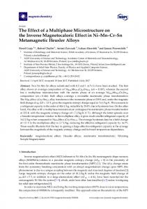
I. INTRODUCTION One of the key steps in the advancement of ceramic processing is the achievement of a special, controlled and reproducible micro(nano)structure. Reducing the dimension of a “meso/macroscopic” phase down to the nanometer scale produces moieties in which interfacial volumes dominate. This results in absolutely unique properties. Sol-gel routes, and more generally synthesis through liquid precursors, offer the possibility to control the structure at the scale of the precursor and its aggregates (1 to 100 nm). This allows the preparation of more homogeneous materials than the usual ball-milling process. Materials made with (or from) nanophases have received considerable attention in the last few years, but their characterization is not easy. A large variety of nanomaterials are now being developed, if not already commercially available, for applications taking advantage of their (1) optical properties (pigments in traditional ceramics and for the cosmetics industry, fluorescent markers, quantum dots, photonic crystals for multiplexing and switching in optical networks, quantum computer components, etc.); (2) mechanical properties (fibers, wear-resistant, anticorrosion, and cutting coatings, “nanopolishing” SiC, diamond, boron carbide powders, high impact strength nanocomposites, etc.); (3) magnetic properties (data storage, reading heads, giant magnetoresistance [GMR] materials, etc.); (4) high specific surface area (propulsion, filters, nanosensors, semiconductor nanowires, catalysts, etc.); (5) electrical properties (miniaturized silicon chips, single electron transistors, carbon nanotubes or even silicon nanotubes transistors, etc.); and (6) biocompatibility (in vivo drug delivery, diagnostic and monitoring devices, etc.). Most of these materials are ceramics synthesized through a route involving a liquid step. In fact, potters and ceramists have been using such nanoscience (clays form a “physical” gel; Figure 12.1a) for thousands of years in clay-based ceramics: most of the properties of traditional ceramics (plasticity, shapability, rheology, low sintering temperature, etc.) are directly related to the fact that natural clay—the raw material—is nanosized and the so-called sol-gel route only results from the transposition of the clay route to simpler oxide, carbide, etc. compositions.1,2 In the last 10 centuries, nanosized ceramic pigment powders were also created to color enamels and glass.3 Because of human eye sharpness, pigment must have a particle size close to 100 nm to give homogeneous coloration. The challenge for ceramists is to achieve perfect control on related properties. This obviously requires correlating the parameters of the synthesis process with the resulting nano/microstructure. This chapter focuses on the ways to prepare multiphase materials and their main controlling parameters, on the precursors and their structure, and on the porosity, densification, and final mechanical properties. The goal here is not to give a complete overview, but to address the most important points and the ways to solve most of the problems with some examples. Particular attention will be given to nondestructive methods able to characterize the materials over different scales (from atomic distances to full size).
DK4027_book.fm Page 305 Monday, May 16, 2005 2:01 PM
Nano/microstructure and Multiphase Materials
305
Polymerized alkoxides Chemical gel from gel-formers
Colloidal sol Physical gel
MIXING liquid
Silanes Silazanes,...
Salt powders or solubles salts (a)
4 ZrO2·6SiO2 4 ZrO2·3P2O5 ZrO2·P2O5 Al2O3 Na2O
SiO2
SiO2 Na2O
Na2O·CaO·2Al2O3
P2O5
ZrO2
SiO2
ZrO2·Na2O
Na2O ZrO2·4SiO2
P2O5
(b)
FIGURE 12.1 (a) Schematic flowchart of hybrid routes. (b) Sol-gel forming compositions (alkoxide route) in the SiO2-Al2O3-ZrO2-P2O5, 4ZrO2·6SiO2-Na2O-4ZrO2·3P2O5, ZrO2Na2O-SiO2, ZrO2-P2O5, ZrO2·Na2O-SiO2, ZrO2·4SiO2-Na2O-P2O5, and SiO2-P2O5Na2O·CaO·2Al2O3 phase diagrams. The representation corresponds to the final oxide composition. Solid line indicates the limit of optically clear gel by slow hydrolysis. Dashed line indicates the limit of easy synthesis of (translucent) monolithic gels. (Reprinted from Colomban, P., Gel technology in ceramics, glass-ceramics and ceramicceramic composites, Ceram. Int., 15, 23, 1989. With permission from Elsevier.)
II. PRECURSORS AND ANALYSIS METHODS Precursors must have different properties:4–14 (1) a high content of the final elements (mostly aluminum, silicon, zirconium, titanium, phosphorus), (2) a low content of health hazardous elements and elements that corrode the equipment (e.g., chlorine, sulfur), (3) a viscosity adapted to the process: low viscosity for preform infiltration, medium viscosity for spinning and coating, (4) a controlled precursor-ceramic transformation (bubbling is researched for foams but not for dense parts), (5) the ability to be mixed with other precursors or to be processed (“good” hydrolysis rate), and (6) low cost. Regarding sol-gel routes, the most used reagents are those made with gelformer compositions: aluminium-s-butoxide [Al(OC4H9)3], tetraethoxysilane [Si(OC 2 H 5 ) 4 ] (and homologous methoxysilane), aluminum-silicon ester
DK4027_book.fm Page 306 Monday, May 16, 2005 2:01 PM
306
Chemical Processing of Ceramics, Second Edition
[(OC4H9)2-Al-O-Si(OC2H5)3], zirconium-i-propoxide [Zr(OC3H7)4], titanium butoxide [Ti(OC4H9)4] and propoxide [Ti(OC3H7)4], tributylborate [B-(OC4H9)3], and tributylphosphate [P-(OC4H5)3].6–17 Figure 12.1b shows the basic SiO2-Al2O3ZrO2-P2O5 quaternary diagram and some related ternary diagrams. The dotted regions correspond to composition ranges easily giving optically clear (high dot density) or translucent (low dot density) gels. The dashed line corresponds to the limit of easy synthesis. The handling of aluminum and some other reagents like germanium propoxide [Ge(OC3H7)4] requires a glove box free of H2O traces. Homemade preparations of very hygroscopic alkoxides guarantees their quality. However, in the preparation of multicomponent materials through the sol-gel route or by mixing organic precursors, determination of the metal element content is not obvious.7 In commercially available reagents, the metal content often varies from batch to batch and a slight prehydrolysis is often observed. The degree of hydrolysis can be determined by nuclear magnetic resonance (NMR), infrared (IR) absorption, or Raman scattering.14,16–18 This modifies the metal content and the viscosity. The viscosity of the alkoxides can be adjusted at values of approximately 1 poise by heating below 80°C for most of the reagents. Mixing of liquid precursors promotes the intimate combination of various precursors at the molecular scale and allows adjustment of the viscosity to void filling requirements. One of the main interests of liquid alkoxides is that they exhibit a rather good ceramic yield: typically the alkoxide-to-ceramic conversion yield is between 20 and 30 wt%. Thermal treatments under various atmospheres (NH3, H2S, CO) lead to (oxy)-nitrides, -sulfides, -carbides, and derivatives.1,19 However, carbides, nitrides, and their oxyderivatives are generally prepared by cross-linking and ceramization of specific precursors: polycarbosilanes, polysilazanes. Since the work of Yajima et al.,20,21 polycarbosilane (PCS) is well known as a precursor of SiC materials.22,23 The high viscosity of this precursor is convenient for fiber spinning, but prevents its use to fill a fiber preform already filled with a submicrometer powder. Unfortunately the oxygen-driven reticulation of the chains of the precursor, convenient for films and fiber, is not obvious inside a thick sample, which makes it difficult to control the stoichiometry in the whole. Polyvinylsilane (PVS) fulfills the specific requirements for the infiltration of a porous body:22 (1) a thermostat behavior with a cross-linking temperature (200°C to 300°C) far enough from the beginning of pyrolysis (400°C) to avoid formation of bubbles during the cycle; (2) a relatively low molecular weight (MW < 1000), which ensures a sufficiently low viscosity (e.g., 0.3 poise at 130°C) to allow injection in the fiber preform at “low” temperatures; (3) a very high ceramic yield: 64% in weight; and (4) a silicon/carbon stoichiometry leading to air-stable materials. A variety of precursors of carbide, nitrides, and their mixture are now available for many applications. Last-generation precursors use γ radiation to develop an intrinsic cross-linking between precursor chains instead of the extrinsic Si-O-Si bridging obtained by controlled oxidation. Generally, the main questions that need an answer are: Is the expected composition and structure achieved? Most of the materials prepared through liquid precursor routes are first obtained in an
DK4027_book.fm Page 307 Monday, May 16, 2005 2:01 PM
Nano/microstructure and Multiphase Materials
307
amorphous or metastable form. These forms are very similar to those obtained by quenching from a high-temperature melt, but usually retain hydrogen (protons, OH groups, and –CH branches).24–26 In the liquid state the local structure is determined by geometry constraints. On the contrary, in the solid state the structure of materials equilibrated at a given temperature is dominated by long-range Coulombic interactions. Knowledge of the phase relationship diagram is mandatory and thermal expansion measurement (Figure 12.2a) is the simplest way to determine it.4,25–28 Differential thermal analysis (DTA) and phase characterization methods (x-ray diffraction [XRD], Raman scattering, IR absorption) are useful methods to confirm the phase relationship. Is the sample free of hydrogen? Sol-gel-prepared ceramics easily retain a few wt% of protons up to 1000°C or more, and these protons drive the sintering and crystallization mechanisms.24,26 Rather similar amounts of hydrogen are retained in carbides/nitrides derived from polymeric precursors (e.g., in SiC fibers thermally treated at approximately 1200°C). This hydrogen can generate unwanted gas departure. Is the density/porosity convenient for the final use? What is the optimum processing temperature? Is the material homogeneous? What are the differences between the skin and the bulk? Where are the second phases located? Another question is how to select the method with the lower cost. The use of hybrid methods in which part of the elements is introduced from metal-organic precursors offers the best compromise (Figure 12.1a).
Shrinkage (%)
0
Powder
Xerogel
5 H2O
10 15
Gel
OH
−
Nucleation
Microhardness/a.u.
5
Mullite Nasicon
104
103 Ceramic Gel
102
20 200
600 1000 Temperature (°C) (a)
1400
0
Glass
500 1000 1500 Thermal treatment temperature/°C (b)
FIGURE 12.2 (a) Comparison of the linear shrinkage of mullite (3Al2O3·2SiO2) micronic powder, 600°C thermally treated gel (xerogel) and pristine gel. (After Reference 87.) (b) Plot of the R.T. microhardness for mullite and Nasicon (Na3Zr2Si3PO12) as a function of thermal treatment. (After Reference 27.)
DK4027_book.fm Page 308 Monday, May 16, 2005 2:01 PM
308
Chemical Processing of Ceramics, Second Edition
The final question is how to control the achieved materials. Methods and representative references are listed in Table 12.1. Two of these methods, the depthsensing indentation and the micro-Raman scattering, were developed recently and will be addressed in the last part of this chapter.
TABLE 12.1 Methods of Analysis for Nano/Microsized Materials Sensitivity
Method
Bond length Structure
Dilatometry
Bond length Structure Composition Bond length Structure Symmetry Composition Geometry
DTA
Bond length Structure Symmetry
X-ray, electron (neutron) Diffraction (TEM) SEM
Composition Geometry Density
Density
Density
Mass Composition
Vibrational spectroscopy (IR, Raman) Microspectros copies
Thermal expansion/ shrinkage Gas adsorption
X-ray (neutron) scattering TG
Information
Advantages
Densification Phase transition Crystallization CTE Anharmonicity Sintering mechanisms Phase transformation /transition Structure Crystallization Phase transition Strain/stress Phase location
Analysis of the whole sample High sensitivity Easy atmosphere control
Structure Phases
Drawbacks Generally destructive
Routine High sensitivity Minor phases can be studied Phase and properties mapping Properties predictions Good database
Ref. 4, 25–28
4, 28
Very different cross sections
16, 51, 52, 89, 94, 107
Destructive Materials to be crystalline
15
Phase locations
5
Sintering
Routine technique
Destructive
7, 36, 40
Porosity Reactivity
Pore size and distribution
30, 31
Phase contrast
Whole sample
Very long time of analysis Difficulty of drying Unequivocal
33, 38
Gas evolution Oxidation
Routine
Destructive
27, 31
DK4027_book.fm Page 309 Monday, May 16, 2005 2:01 PM
Nano/microstructure and Multiphase Materials
309
III. DENSIFICATION We will take examples among silicates, aluminates, and zirconates prepared from the alkoxide sol-gel route that serve as the basic compounds for many applications. Figure 12.3 illustrates the structure change at the bond length scale when a gel/porous glass densifies by dehydroxylation-crystallization. The departure of some OH groups destabilizes the pore surface and gives rise to a high surface mobility. Rearrangement in the crystalline form induces densification.24,26 Consequently the microhardness increases (Figure 12.2b).27 This sketch illustrates that the densification and crystallization process is intimately related to the gel structure.
A. GEL STRUCTURE
AND
COMPOSITION
Gelation of liquid oxide precursors like alkoxides (M(OR)n) results from hydrolysis-polycondensation: M(OR)n + nH2O → M(OH)n + nROH,
(12.1)
and simultaneously, generally1,2,8–11,29 M(OH)n → n/2H2O + nMOn/2.
(12.2)
After drying the resultant gel has a complex composition such as MOn-x-ε (OH)2x(O-R)εmH2O
(12.3)
with x ~ 0.1 to 0.3, m = 3 to 6, and ε ~ 0.01.30–33 These gels are made of small polymeric entities (diameter 0.5 nm to 5 nm), which are more or less aggregated and densely packed according to the process (hydrolysis-polycondensation rate, initial alkoxide-to-solvent and alkoxide-to-water ratios).17,18,33 Small angle x-ray/neutron diffraction analysis and scanning electron microscopy (SEM)/transmission electron microscopy (TEM) images show that oxide gels are made of
FIGURE 12.3 Sketch of the nucleation-densification process (b) involved with the dehydroxylation of a gel surface (a). (After Reference 27.)
DK4027_book.fm Page 310 Monday, May 16, 2005 2:01 PM
310
Chemical Processing of Ceramics, Second Edition
FIGURE 12.4 Scanning electron micrography of optically/translucent NASICON gels (a-c) prepared by different gels routes. An example of fine grained optically clear ceramic (1400°C fired mullite) is shown in (d) (a-d, reprinted from Ceramic Powder Science and Technology, Messing, G., Ed., © 1989, with permission from The American Ceramic Society; (d) after “Sciences & Techniques”, Céramiques: les progrès de la Chimie, © Ph. Colomban).
rather globular polymeric entities (diameter 1 nm to 2 nm), which are more or less densely packed according to the hydrolysis-polycondensation rate and the initial alkoxide-solvent-water ratios. An example is given in Figure 12.4: the size of the aggregated moieties is
Si-R′n
>
Autoclave
Cross-linking
M(OR)n
Polycondensation + Pyrolysis
FIGURE 12.10 Schematic of the oxide (alkoxides) or nonoxide (polymers) matrix precursors infiltration for fabricating three-dimensional reinforced composites. (After Reference 87.)
prepare SiC matrix,85 and then, during pyrolysis, into a refractory intergranular phase. This second step can be repeated as many times as necessary to optimize the interparticle bonding. As explained in the previous part, optimization of the microstructure might involve (1) an increase in ceramic yield by the pyrolysis of the precursor, (2) an increase in thermostability of the resultant phase, in order to limit the shrinkage of the refractory interphase and postpone the whole matrix shrinkage toward higher temperatures, or (3) the optimization of the fiber-matrix interface. For instance, various polymeric precursors can lead to inert, refractory, and nonreacting interphases: zirconium-i-propoxide as zirconia precursor, aluminum-butoxide as alumina precursor, lanthanum-alkoxide, and homologues as rare earth oxide precursors. Sometimes titanium-i-propoxide, tetraethoxysilane, and aluminum-silicon ester can be used as rutile, silica, and aluminosilicate precursors, respectively. These last three compounds, which slightly react with many oxides, might also be used to strengthen the interparticle bonds. It is very important, however, to simultaneously maintain a net-shape sintering behavior. The room-temperature and high-temperature flexural strength was increased after five (Figure 12.11) cycles of postinfiltration in situ hydrolysis-polycondensation and 1000°C heating, zirconium-i-propoxide being used for the first four cycles and aluminum-silicon ester for the last one.12,83 Confirmation was given by tensile test, at room temperature. The increase in mechanical strength arises from the filling of the voids (porosity decreases), but also from the blocking of shrinkage due to the zirconia “inert” phase. The high stability of zirconia coatings has been used in many oxide-oxide composites. The addition
DK4027_book.fm Page 321 Monday, May 16, 2005 2:01 PM
Nano/microstructure and Multiphase Materials
321 80
4 Zr + AlOSi
100
4 Zr + AlOSi 1000°C
60 60
40 8 Zr C/Al2O3
20
20 0
0
1
0
2
0
.2
.4 Strain (%)
U. Strength (MPa)
(a)
(b)
160
600 +Zr
120
400
4 (AL + Zr) 8 Zr
80
200 0
.6
40 0
10
20 Porosity (%) (c)
30
40
0
1000 1200 1400 Temperature T.T. (°C) (d)
FIGURE 12.11 Improvements of the mechanical properties of three-dimensional reinforced CMCs by hybrid infiltration routes: (a) R.T. flexural stress-strain plots for a threedimensional carbon fiber reinforced composite before and after cycles of infiltration (comparison between eight cycles with zirconium propoxide and four cycles plus a last infiltration with aluminum-silicon ester; (b) plot of the mechanical strength as a function of the final open porosity for composites and matrix of equivalent porosity, before and after infiltration (Reprinted from Colomban, P. and Wey, M., Sol-gel control of the matrix net-shape sintering in 3D reinforced ceramic matrix composites, J. Eur. Ceram. Soc., 17, 1475, 1997. With permission from Elsevier); (c) R.T. tensile behavior; (d) comparison of the R.T. mechanical strength after thermal treatments at various temperatures. (Reprinted from Colomban, P., Tailoring of the nano/microstructure of heterogeneous ceramics by sol-gel routes, Ceram. Trans., 95, 243, 1998. With permission from The American Ceramic Society.)
of aluminosilicate precursor for the last infiltration strengthens the bridge between particles and decreases the open porosity. Tensile measurements show that the mechanical properties achieved through the oxide route are very similar to those of the usual SiC made by the CVI process, although the matrix Young’s modulus is lower in the former (30 GPa instead of 75 GPa for the CVI SiC matrix). A rather pronounced hysteresis in loading-unloading cycles is observed. The same behavior is observed for composites prepared by combining SiC powder and PVS infiltration.23,84
DK4027_book.fm Page 322 Monday, May 16, 2005 2:01 PM
322
Chemical Processing of Ceramics, Second Edition
Alloying the materials obtained from liquid precursors offers a new route to create particular micro/nanostructures in order to optimize the properties of porous materials.
E. FUNCTIONALLY GRADED MATERIALS By selecting the appropriate sol-gel precursors, the dwell temperature required to achieve maximum densification can be raised or lowered by about 100°C.1,36 This makes it possible to combine several kinds of impregnated fiber/matrix interphases in the same composite in order to tailor its physical and/or chemical properties for a particular application. Composites have been fabricated that combine various kinds of woven fibers (SiC Nicalon, Nextel, Almax, Saphikon) with various kinds of matrices (LAS, mullite [a pure dielectric with a real microwave permittivity close to 5 at 10 GHz], Nasicon [a solid electrolyte with the structural formula Na1+xZr2SixP3xO12 (0 x 3) offers the advantage of an electrical conductivity varying by four orders of magnitude as a function of x], celsian [a corrosion-resistant ceramic], zirconia)6–10,76,78,79,86,87 in order to tailor thermomechanical and electromagnetic properties simultaneously. The processing can be summarized as follows: The fibers of a two-dimensional woven fabric are first impregnated with a liquid alkoxide mixture, which fills the voids between the fibers, transforms in situ into a gel by reaction with atmospheric moisture, and will be converted into a (glass)-ceramic by pyrolysis during the hot-pressing of prepreg fabrics covered with the matrix powder precursors. Depending on both the matrix and the fibers, several different “interface precursors” can be used, either alone or in various combinations. Finally, the doubly impregnated, coated woven fabrics are stacked in a graphite mold and hot-pressed, typically between 950 and 1400°C. By selecting the appropriate solgel precursors, the dwell temperature required to achieve maximum densification can be raised or lowered by about 100°C. This makes it possible to combine several kinds of fiber-reinforced layers in the same composites in order to tailor, unidirectionally, the microwave absorption along the direction perpendicular to the body. Examples given in Figure 12.12 show (1) a composite consisting of a zirconia matrix and a mullite matrix, both reinforced by SiC Nicalon NLM 202 fibers (4 + 4 layers), and (2) NASICON matrix composite reinforced on one side by low-permittivity Nextel mullite woven fibers (4 layers) and on the other side by conducting Nicalon SiC woven fibers (2 layers).
V. CHARACTERIZATION OF MULTIPHASE MATERIALS One of the difficulties in the characterization of multiphase materials is the need to analyze the different phases at various scales: at the scale of each phase, at the scale of their association (interfaces and intrafaces), and at the scale of the parts. We will address two methods, which can be used very rapidly for this type
DK4027_book.fm Page 323 Monday, May 16, 2005 2:01 PM
Nano/microstructure and Multiphase Materials
323
FIGURE 12.12 Examples of FGM CMCs: (left) the combination of NLM Nicalon SiC fiber reinforced zirconia (in white) and mullite (in black) matrices; (right) a Nasicon matrix reinforced with mullite (Nextel) and SiC (NLMTM) fibers (see the sketch). (Reprinted from Colomban, P., Process for fabricating a ceramic matrix composite incorporating woven fibers and materials with different compositions and properties in the same composite, Mater. Technol., 10, 89, 1995. With permission.)
of study. Both methods are associated with optical microscopes, which provides easy analysis of regions ranging in size from a few square centimeters to 1 µm2.
A. DEPTH-SENSING MICROINDENTATION The measurement of local mechanical properties is an important step in understanding of the macroscopic behavior of multiphase materials. The indentation hardness test is probably the simplest method of measuring the mechanical properties of materials. Figure 12.2b shows the evolution of the microhardness as a function of the thermal treatment temperature of a Nasicon sample. The use of load-controlled depth-sensing hardness testers which operate in the (sub)micron range enables the study of each component of the composite more precisely. Following the work of Loubet et al.,88 Young’s modulus (E) and Vickers’ microhardness (Hv) can be extracted from the unloading part of load-displacement plots by considering the different contributions of the elastoplastic behavior of the indented materials. Figure 12.13a shows a schematic of an indentation test and Figure 12.13b gives the corresponding curves of loading and unloading versus in-depth penetration. For materials with high plasticity, the remnant penetration depth of indentation (hp) is close to he, given by the intersect of the initial unloading step tangent with the x-axis; for plastic material hp = hmax. The area delimited by loading and unloading curves is proportional to the work of indentation. On the other hand, the hysteresis is very small (hp