microwave characterization of dielectric material using a combination of finite ... waveguide containing a lossy dielectric material such as a ceramic material or ...
ADVANCES IN MODELING OF MICROWAVE SINTERING 12th Seminar Computer Modeling in Microwave Engineering & Applications, Grenoble, France, March 8-9, 2010
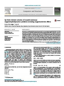
Microwave Finite Element Modeling – Applications to Coupled Electromagnetic-Thermal Problems and Characterization of Dielectric Materials Hulusi Acikgoz, Yann Le Bihan, Olivier Meyer, and Lionel Pichon Laboratoire de Génie Electrique de Paris, SUPELEC; UPMC Universite Paris 06; Universite Paris Sud-P11, Gif-sur-Yvette Cedex, France This talk reviews research work carried out in the Laboratoire de Génie Electrique de Paris during the last decade about finite element modeling for microwave engineering applications. The first part is devoted to coupled electromagnetic-thermal problems. In particular the microwave heating of dielectric material located in a coaxial cell will be presented. The second part summarizes recent work dedicated to microwave characterization of dielectric material using a combination of finite element methods and neural networks. It is hoped that the material of this paper could help to evaluate the potential of the finite element technique for microwave sintering.
Introduction Computational methods are playing an increasingly important role during the design step in microwave engineering. This is the case for microwave sintering. In [1,2] for example, the FDTD method was shown to provide an efficient approach to electromagnetic modeling of multimodal cavities and microwave sintering. Also in [3, 4] the TLM was successfully applied in computational electromagnetics relevant to microwave sintering. Among the different numerical methods the finite element method is the most flexible. It allows complex geometries to be modeled and easily takes into account inhomogeneous materials, while providing an accurate local analysis when solving partial differential equations. In this talk we present research work achieved during the last decade in the Laboratoire de Génie Electrique de Paris devoted to microwave engineering applications involving the finite element method. In the first part the microwave heating process will be considered. The time harmonic electromagnetic problem is coupled with the transient heat equation. The temperature dependence of electromagnetic and thermal parameters is taken into account. Both bounded and unbounded problems are addressed. In the second part a methodology combining finite elements and neural networks is developed in order to characterize dielectric materials while solving the inverse problem of reconstructing permittivity from the measured reflection coefficient. Coupled Electromagnetic-Thermal Analysis Let us consider a region Ω containing lossy dielectric material and surrounded by a boundary Γ . Starting from the vector wave equation and using Green’s identity the weak form of Maxwell’s equations in terms of the electric field e can be derived:
9
ADVANCES IN MODELING OF MICROWAVE SINTERING 12th Seminar Computer Modeling in Microwave Engineering & Applications, Grenoble, France, March 8-9, 2010
1 curle.curle'dΩ − k 02 ε r e.e'dΩ + iωµ 0 (n × h ).e 'dΓ = 0 µ Ω r Ω Γ
(1)
where µ r is the relative permeability, ε r is the relative permittivity, ω is the angular frequency and k 0 is the wave number ( k 02 = ε 0 µ 0 ω 2 ). The different parts of Γ include electric walls (perfectly conducting walls), symmetry planes, artificial boundaries surrounding the computational domain (in the case of unbounded problems) and ports (access planes in the case of a microwave cavity). The boundary term in (1) is determined on a different part of Γ according to the boundary condition type. In this work two different types of tangentially continuous elements have been considered [5]. The temperature T of the heated volume V is determined by solving the heat equation in weak form: d ∂T ρ C p T dV + k gradT.gradϕ dV − k ϕ dγ = Qϕ dV dt V ∂ n V ∂V V
(2)
where ρ , C p , k, Q are respectively the density, specific heat capacity, thermal conductivity and heat power density. Convective radiation conditions are used on the boundary. Equation (2) is discretized using tetrahedral nodal elements of first order. Equations (1) and (2) accounting for boundary conditions are solved by iterations. In the heating process the temperature changes occur much more slowly than variation of the electromagnetic field, so we may assume that the electromagnetic time-harmonic steady state is reached for each temperature distribution. The coupling is taken into account through the dissipated power density per unit volume:
Q=
1 2 ωε 0 ε r " e 2
(3)
In a first example [6], the coupled model is used to analyze a short circuited standard waveguide containing a lossy dielectric material such as a ceramic material or foodstuff. The convective boundary condition is applied on the face between air and dielectric. We suppose that the faces against the waveguide walls are thermally isolated. A typical finite element mesh is shown in Fig.1. Symmetry allows us to model only one quarter of the structure. The same mesh is used for the thermal problem in the dielectric region. The cavity is excited by a TE 10 mode at 2.45 GHz. The electromagnetic and thermal properties of the material are taken from [7]. The power generated by the exciting source is 1 kWh. The initial temperature is 25°C. The convective heat parameter is taken to be constant for the entire simulation ( h = 50 W / m 2 °C ). Fig. 2 shows the evolution of temperature in the lossy dielectric medium at different time steps in case of aluminum nitride. The second example consists of a measurement cell used in controlling the microwave process for polymer curing; it is a portion of a cylindrical waveguide short-circuited at one end and excited at the other end by a circular coaxial cable (Fig. 3). This cell belongs to an instrumentation that allows dielectric property measurements (permittivity, relaxation frequency)
10
ADVANCES IN MODELING OF MICROWAVE SINTERING 12th Seminar Computer Modeling in Microwave Engineering & Applications, Grenoble, France, March 8-9, 2010
Fig. 1. Mesh of the dielectric waveguide
Fig. 2. Distribution of the temperature in Aluminum Nitride (1/4 th of dielectric)
in a broad frequency range (1 MHz – 10 GHz). The sample under microwave curing is a mixture of epoxy resin and hardener. The cell is excited by a TEM mode. Considering the axial symmetry of the structure, an axi-symmetric model was developed [8]. It uses the azimuthal component of the magnetic field. To illustrate the computation, Fig. 4 shows the evolution of 11
ADVANCES IN MODELING OF MICROWAVE SINTERING 12th Seminar Computer Modeling in Microwave Engineering & Applications, Grenoble, France, March 8-9, 2010
Fig. 3. Coaxial cell
Fig. 4. Variation of temperature versus time
Table 1. Physical Parameters of Tissue Used in the Computation εr
C p (J / kg°C)
ρ (kg / m 3 )
k (W/m°C)
Fat
7 – i3
2.3 x 10 3
0.93 x 10 3
0.29
Muscle
50 – i24
3.55 x 10 3
1.04 x 10 3
0.43
temperature in the middle of the sample versus heating time at 434 MHz for an incident power of 70 W. The relaxation frequency is also plotted as a comparison: numerical modeling gives some insight into the relationship between the simulated macroscopic temperature and the mesoscopic relaxation frequency related to the behavior of the molecular dipoles. The third example was studied in order to test the ability of the coupled electromagnetic model to deal with hyperthermia problems and to address the case of an unbounded computational region [9]: a lossy dielectric sphere is illuminated by an incident plane wave with a frequency f = 433 MHz (usual hyperthermia frequency). It has a radius R = 0.36 λ ( λ is the wavelength in free space). This geometry of the sphere was preferred because in this case analytical solutions exist for the electromagnetic equation and allowed us to validate the numerical method. The values of the physical parameters are those of fat and muscle (Table 1). When the microwave source is switched on (t = 0), the temperature is the equilibrium temperature of the human body (T0 = 37°C) . Due to symmetry, only a quarter of the sphere is studied. Fig. 5 shows a typical mesh used for the computation where are shown the boundaries of the dielectric region and the outer boundary located at R = 0.45λ . In Fig. 6, we show the computed temperature distribution in fat tissue after 600 s of electromagnetic heating. This distribution fits that of the heating power. The maximum temperature reached is 44.5°C and is located near the surface of the dielectric sphere. Thermal gradients have the highest values in the hot region.
Microwave Dielectric Characterization Determination of dielectric constant ’ and loss factor ’’ of dielectric materials is a difficult problem. In this paper the characterization technique is based on the coaxial cell presented 12
ADVANCES IN MODELING OF MICROWAVE SINTERING 12th Seminar Computer Modeling in Microwave Engineering & Applications, Grenoble, France, March 8-9, 2010
Fig. 5. Typical electromagnetic mesh.
Fig. 6. Distribution of temperature (600 s).
before. Nevertheless, for a coaxial waveguide, the relation between the admittance measured at the discontinuity plane of the waveguide and the complex permittivity (direct model) can rarely be inverted. An alternative is then to use a direct model in an iterative procedure to reduce the difference between the calculated admittance and the measured one. However, in many cases an analytical solution does not exist and numerical solutions are computationally expensive when using an iterative procedure. In order to avoid the drawbacks of an iterative procedure, a more efficient approach is to use a parametric model adjusted with a database. A good kind of candidate for this is artificial neural networks (ANNs) since they are universal and parsimonious models and can allow for approximation of a wide range of functions provided that they are previously trained. The training consists of adjusting the parameters of the ANNs so that it correctly approximates the physical behavior of the system. Our approach is based on the combination of ANNs and the finite element method [10]. The necessary data sets are created by the finite element method. The inputs of an ANN are the value of complex impedance (real part G, imaginary part B) and the measurement frequency (f). The output are the ( ’, ’’) pairs (Fig. 7). The use of ANNs is interesting since they do not require analytical solutions and can be implemented without any limitation on the frequency. The first inversion results obtained with ANNs (from 1 MHz to 1.8 GHz) are compared with those obtained from a protocol (SuperMit) used for microwave characterization and having an analytical solution on a wide band of frequency (up to 18 GHz with an APC7 standard). The inverse model of this second protocol can be easily obtained by an iterative procedure using the gradient method (Fig. 8).
Conclusion We showed in this paper that the finite element method provides an efficient tool for dealing with coupled electromagnetic-thermal problems and that a numerical electromagnetic model can be efficiently combined with neural networks in order to solve inverse problems involved in 13
ADVANCES IN MODELING OF MICROWAVE SINTERING 12th Seminar Computer Modeling in Microwave Engineering & Applications, Grenoble, France, March 8-9, 2010
Fig. 7. Structure of an ANN (Multi-Layer Perceptron)
Fig. 8. Reconstruction of the permittivity of ethanol
microwave dielectric characterization. Capabilities of the models could be developed in the future in order to address microwave sintering.
References [1] M. F. Iskander, R.L. Smith, A.O.M. Andrade, H. Kimrey, Jr., and L.M. Wal, FDTD simulation of microwave sintering of ceramics in multimode cavities, IEEE Trans. Microwave Theory and Techn., vol. 42, no. 5, pp. 793-800, 1994. [2] J. White, M. F. Iskander, and Z. Huang, Development of a multigrid FDTD code for threedimensional applications, IEEE Trans. Antennas and Propag., vol. 45, no. 10, pp. 1512-1517, 1997, [3] A. Amri and A. Saidane, TLM simulation of microwave hybrid sintering of multiple samples in a multimode cavity, Intern. J. Num. Modelling, vol. 16, no. 3, pp. 271-285, 2003. [4] A. Amri and A. Saidane, TLM modelling of microwave sintering of multiple alumina samples, IEE Proc., Science, Measurement and Technology, vol. 151, no. 4, pp. 259-266, 2004. [5] J. Jin, The Finite Element Method for Electromagnetics, 2nd Ed., John Wiley and Sons, 2002. [6] A. Sekkak, L. Pichon, and A. Razek, 3D FEM magneto-thermal analysis in microwave ovens, IEEE Trans. Magnetics, vol. 30, no. 5, pp. 3347-3350, 1994. [7] F.M. Clark, Insulating Materials for Design and Engineering Practise, John Wiley and Sons, 1963. [8] L. Pichon and O. Meyer, Coupled thermal-electromagnetic simulation of a microwave curing cell, IEEE Trans. Magnetics, vol. 38, no. 2, pp. 977-980, 2002. [9] A. Sekkak A., V.N. Kanellopoulos, L. Pichon, and A. Razek,. An electromagnetic and thermal analysis in biological bodies using 3D FE and absorbing boundary conditions, IEEE Trans. Magnetics, vol. 31, no. 3, pp. 1865-1868, 1995. [10] H. Acikgoz, Y. Le Bihan, O. Meyer and L. Pichon, Neural networks for broad-band evaluation of complex permittivity using a coaxial discontinuity, EPJ Applied Physics Journal, vol. 39, no. 2, pp. 97-201, 2007.
14