Sep 18, 2011 - The system consists of a PC, a marker less hand tracker for input, and a noncontact ... interfaces keep users' hands away from getting dirty.
SICE Annual Conference 2011 September 13-18, 2011, Waseda University, Tokyo, Japan
Takayuki Hoshi1 1
The Center for Fostering Young and Innovative Researchers, Nagoya Institute of Technology, Japan (Tel: +15235446; mail: starnitech.ac.jp)
A system is proposed which enables users not only to operate computers by moving their fingers in midair but also to feel touch feedback on their fingers. The system consists of a PC, a markerless hand tracker for input, and a noncontact tactile display for feedback. The tactile display utilizes ultrasound to produce tactile stimulation from a distance. The principles of the tactile display are described and the developed prototype system is introduced. User interface, tactile display, airborne ultrasound, acoustic radiation pressure.
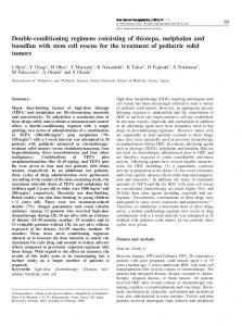
Recently, various technologies are developed which enable users to operate computers by moving their hands in air [1][2][3][4][5]. Such technologies would be used as interfaces with PCs, games, portable devices, digital signage, and so on. They are also promising in hospitals, food factories, and public spaces because the interfaces keep users’ hands away from getting dirty. Currently, visual and/or audio feedback is usually provided. In [3], vibrotactile feedback is provided on the hand holding the portable device. For more intuitive feedback, it is preferable to provide tactile stimulation directly on the hand or finger associated with a cursor. This paper proposes to combine an aerial input system with a noncontact tactile display (Fig. 1). The aerial input system uses a depth camera to track a user’s hand. The tactile display utilizes airborne ultrasound to stimulate the user’s hand tactually in midair [6]. This configuration is suitable for daily life because it demands no attachments on a user’s hand for both of hand tracking and tactile feedback. For example, users can use the system with their hand being wet or dirty. They feel free to use it for a short time. They can use it simultaneously or alternately.
(a) Photo.
The noncontact tactile display is based on a nonlinear phenomenon of ultrasound: Acoustic radiation pressure. Assuming a plane wave, the acoustic radiation pressure P [Pa] is described as
P = αE = α
I p2 =α 2 c ρc
(b) Illustration (top view). Fig.1 Developed aerial interface system. The Phased Array Focusing technique is used to produce the radiation pressure perceivable by human skins. The focal point of ultrasound is generated by setting adequate phase delays of multiple transducers. Inthe previous study [6], it is confirmed that the force of 16 mN is produced when 324 transducers are employed. In addition, the focal point can be moved to an arbitrary position by controlling the phase delays. It is theoretically derived that the spatial distribution of ultrasound generated from a rectangular transducer array is nearly sincfunction shaped [6]. The widths of the main lobe in two directions parallel to the sides of the rectangular (wu [m] and wv [m]) are written as
(1)
where E [J/m3] is the energy density of ultrasound, c [m/s] is the sound speed, p [Pa] is the RMS sound pressure of ultrasound, and ρ [kg/m3] is the density of medium. α is the constant depending on the amplitude reflection coefficient R at an object surface; α ≡ 1+R2.
- 608 -
PR0001/11/0000-0608 ¥400 © 2011 SICE
wu =
2λ R 2λ R and wv = Du Dv
(2)
where λ [m] is the wavelength of ultrasound, R [m] is the focal length, and Du [m] and Dv [m] are the side lengths of the rectangular array. Eq. (2) indicates that the spatial resolution and the array size are in the relationship of tradeoff. In the current prototype, the ultrasound transducers are arranged in a rectangular area whose Du and Dv are 20 cm and 10 cm, respectively. The resonant frequency of the transducers is 40 kHz (i.e. λ =8.5 mm). Then, wu and wv are 2.6 cm and 5.1 cm, respectively, when R is set at 30 cm. Because the width of 5.1 cm is too wide to target a single finger, three fingers or a palm is the target of the prototype.
Fig.2 Experimental results. The black dot is the mean value for each subject. The bar connects the maximum and minimum values.
blocked off by hearing a white noise with headphones. The results are shown in Fig. 2. The overrun (vertical axis) is the distance travelled along Y direction after the subject’s hand passed the XZ plane. In the ideal case, the overrun would be zero because the virtual touch screen is set at the XZ plane. Fig. 2 shows the mean value as a black dot and the maximum and minimum values as both ends of a vertical bar for each subject. The mean value is the offset of position recognition and it can be compensated for each person. The difference between the maximum and minimum values indicates the degree of ambiguity. The offset and ambiguity averaged among the trials of all the subjects are 17 mm and 19 mm, respectively. That ambiguity implies that an interval wider than 19 mm is required when multi layered screen is reproduced.
A midair interface system (Fig. 1) was developed by employing the airborne ultrasound tactile display. The system consists of a laptop PC, the tactile display, and a handtracker. A circular cursor on the LC of the laptop PC moves according to the position of a user’s hand in X and Z directions. The size of the cursor changes according to the hand position in Y direction. The virtual touch screen is set at XZ plane (i.e. y = 0) and tactile feedback is provided when the user’s hand is within the space where y ≤ 0. With this system, users can click, drag, draw, select, and so on, receiving not only visual but also tactile feedback. inect [5] is used as a handtracker in this system. It is a depth camera based on an infrared pattern projected over its field of vision. The spatial resolutions are about 1 mm in all X, Y, and Z directions at a distance of 60 cm from the sensor. Currently, the nearest point and its vicinity are detected as a hand. An algorithm of bone estimation would be adopted to improve robustness of hand tracking. The work space is a 20×20×20 cm3 cubic area and it is divided into 5.0×5.0×12.5 mm3 subareas. The center positions of the subareas are selectable as the position of the focal point. That is, the focal point moves among 40×40×16 discrete positions. While the amplitude of ultrasound is variable with PWM, it is tentatively fixed at the maximum value (i.e. 50percent duty ratio).
This work was mainly carried out as a cooperative research with Samsung Electronics Co., Ltd. It was also partly supported by the Japan Society for the Promotion of Science (JSPS) the rantinAid for esearch Activity Startup (21800039).
[1] WiimoteProject, http://johnnylee.net/projects/wii/.
An experiment was conducted in order to examine how surely users could feel the virtual touch screen. Ten volunteers (between 21 and 30 years old, all male, and righthanded) took part in it. The subject was instructed to sit on a chair in front of the aerialinput system, move his hand toward the PC, and stop his hand when he felt tactile stimulation on his hand. Then the position of his hand was recorded. He repeated the trial 10 times. The focal point was generated at the center of the vicinal area around the nearest point. The modulation frequency was 200 Hz. The visual information was shut off by closing his eyes and the auditory information was
- 609 -


![TuiJ=]] Download 'Midair' Site for Book Reviews](https://m.moam.info/img/260x300/tuij-download-midair-site-for-book-reviews_647a178e097c476d028c5934.jpg)