and Michael R. Christian, Member.. ZEEE. Abstract- ...... the B.S. degree in physics from Fordham University, at the time of publication. Bronx, NY, in 1966, and ...
IEEE TRANSACTIONS ON ANTENNAS AND PROPAGATION, VOL. 44, NO. 5, MAY 1996
Millimeter-Wave Specular and Diffuse Multipath Components of Terrain R a m M . Narayanan, Senior Member, IEEE, Daniel D. Cox, James M. Ralston, Senior Member, IEEE, and Michael R. Christian, Member.. ZEEE
Abstract- Multipalth interference data were obtained at a frequency of 95 GHz over pathlengths of 100-250 m by measuring height-gain interference patterns over various types of terrain. Data were collected over grass, lake, ice, snow, concrete, asphalt, and gravel surfaces. The transmit antenna was kept fixed, while the receive antenna translated vertically resulting in grazing angles between approximately 0.5-2.0". Full illumination of the Fresnel zones was accomplished by broad-beamwidth horn antennas at both ends. Measured interference patterns indicate the presence of both specular and diffuse multipath components. A technique was developed to separate these components by filtering in the spatial Fourier-transform domain by appropriate choice of the notch frequency for the specular component and the bandpass-filter bandwidth for the diffuse components. The notch frequency is chosen according to system geometry considerations. Using this unique separation technique, specular and diffuse reflection coefficients were deduced for various terrain types. The separation technique developed in this paper can be readily applied to existing height-gain data if the system geometry is known.
M
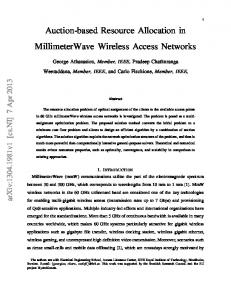
ILLIMETER- WAVE radar, guidance, and communication systems near the surface have to contend with multipath propagation over different types of terrain cover. Multipath is defined as the propagation of a wave from one point to another by rnore than one path, usually a direct path and a ground reflected path [I]. If the reflection surface is flat and smooth (compared to wavelength), the multipath is specular while irregular surfaces contribute to diffuse multipath. In many cases, both specular and diffuse reflected components are present. Although specular multipath is a well-known cause of erratic elevation tracking, its effects are usually deterministic. Thus, if the pertinent radar characteristics, reflection-surface characteristics and milltipath geometry are specified, the results can be computed [ 2 ] .Diffuse multipath, on the other hand, can only be analyzed statistically due to the irregular nature of
Manuscript received March 13, 1995; revised September 30, 1995. This work was supported by Contract DAAL03-91-G-0034 awarded by the U.S. Army Missile Command through Battelle Delivery Order 0479. R. N. Narayanan and 13. D. Cox are with the Department of Electrical EngineeringICenter for Electro-Optics, University of Nebraska, Lincoln, NE 68588 USA. J. M. Ralston is with the Institute for Defense Analyses, Alexandria, VA 2231 1 USA. M. R. Christian is with the U.S. Army Missile Command, Redstone Arsenal, AL 35898 USA. Publisher Item Identifier S 0018-926X(96)03220-6.
Direct Path
h
r
t
(b) Fig. 1. (a) Specular multipath situation and (b) diffuse multipath situation.
the reflective surface. Although theoretical models have been developed to djescribe specular and diffuse multipath phenomena, these have not been tested owing to lack of extensive well-characterized data. This problem is of potential interest to the military in battlefield scenarios where millimeter-wave active sensors ,are employed for obtaining good penetration in fog and smoke, with reasonable angular resolutions. Multipath data in the 35 and 95 GHz atmospheric windows are virtually nonexistent, except for some limited data acquired over snow-covered terrain [3], [4]. A comprehensive simulation study of the effects of multipath on low-angle tracking at 94 GHz specifically pointed out the need to acquire additional multipath interference data [5]. This paper summarizes our investigation into the multipath characteristics over various types of homogeneous terrain. Based on our r:xperimental studies, we have developed techniques to separate the specular and diffuse components of the multipath signal. Section I1 addresses various theoretical issues related to the multipath problem. Section I11 summarizes the experimental observations of multipath interference using our W-band system. Section IV discusses and analyzes the results, while Section 'V presents conclusions. .OO O 1996 IEEE
IEEE TRANSACTIONS ON ANTENNAS AND PROPAGATION, VOL. 44, NO. 5, MAY 1996
Fig. 2. First Fresnel zone extent.
A. Height-Gain Curves Several methods lend themselves to the separate measurement of direct and multipath components in the received signal: i) time-of-arrival difference using extremely fine-time resolutions, ii) angle-of-arrival difference using monopulse antennas, and iii) phase interference (height-gain curves) using a relatively simple transmit-receive system. Using the phaseinterference method, the vertical field distribution can be probed to determine the multipath structure. The total power at the receiver, assuming isotropic antennas, is given by [6]
facet
r
h t
where Po is the direct signal (in the absence of multipath), p is the magnitude of reflection coefficient of the ground which is denoted by p, or p d , depending on whether the reflection is specular (phase-coherent) or diffuse (phase-incoherent), respectively, and 4 is the phase angle between the direct and the multipath signal, varying in the range [O; 2n]. This variation is systematic in the case where the ground reflection is specular, while it is random when the ground reflection is diffuse. In the absence of multipath, PT/Po= 1. Specular Multipath: If only specular multipath [as shown in Fig. l(a)] were to exist, the ratio PT/Powill vary between (1- P , ) ~and (1 p,)' as the phase is varied by, say, moving the receive antenna vertically. The phase angle 4 can be shown to be
+
where p = 2.ir/X,OR is the path difference between the direct ray and the specularly reflected ray, and 4o in the phase change
(b)
Fig. 3. Facet tilt angles at first Fresnel zone ends close to (a)transmit antenna and (b) receive antenna.
due to reflection. The path difference AR can be shown to be
[71
where ht is the transmit antenna height, h, is the receive antenna height, X is the wavelength, and R is the distance between the antennas. The phase change due to reflection 40 can be obtained explicitly from the Fresnel equations which are treated later. For the dielectric surfaces under consideration in this paper, and at near grazing incidence, which is the case here, this value is very close to T .
629
NARAYANAN et al.: MILLIMETER-WAVE SPECULAR AND DIFFUSE MULTIPATH COMPONENTS OF TERRAIN
Thus, the phase angle
4 can be written
quantities in place of the unprimed. We can show, through simple geometry, that
as
Defining the normalized total power P = P T / P ~ we have for specular multipath -
P(h,) = 1
+ p;
- 2 p , cos
Let ~ ( k )the , Fourier transform of P(h,), be defined as ~ ( k =)
P(h,) exp (-j27rkh,) dh,.
(6)
For a multipath-free situation p, = 0, and we can show ~ ( k=)
and
exp {-j27rkh,) dh, = S(k)
since a is small. Positive values of a occur when the facet is tilted toward the transmitter, while negative values of n occur when the facet is tilted toward the receiver. In the above, Rt is the location of the facet from the transmit antenna, sometimes referred to as the glistening point. The effect that this glistening point has is or1 the phase 4 which is now
(7)
yields a spike in k-space at k = 0. With specular multipath present, we can show
The peaks in the Fourier transform due to this element of diffuse scattering occur at k = $[2(ht Rta)/XR],and its magnitude is p d , where pd is the diffuse reflection coefficient. Note that the phase term exp {- j(47r/XR)(ht R t n ) ( RR t ) n ) is disregarded since it has unit amplitude. In addition, diffuse scattering also causes an increase in the magnitude at Ic = 0 by an amount equal to p:. In general, a1 rough surface can be approximated as arising out of a combination of facets oriented in various directions. Thus, there exist a multitude of glistening points at Rt,, corresponding to each facet tilt angle of a,, n = 1 to N. Each such facet has a (diffuse) reflection coefficient of pd,. In this case, the total normalized power is given by
+
+
Thus, three spikes are observed in k-space: a modified spike at 5 = 0 of magnitude (1 p:) and two spikes at k = f (2ht/XR)of magnitude p,. Knowledge of the measurement geometry, therefore, will allow us to isolate the multipath component at f(2ht/XR)by filtering. As can be noted above, the specular multipath interference pattern shows constant component (1 added to a sinusoidal variation with height as the receiver translates vertically keeping th~etransmitter height fixed, i.e., keeping ht = constant. From ( 9 , the spatial period of this sinusoidally varying component h of the normalized total power due to vertical translation of the receiver can be deduced as
+
+ pz)
Equation (9) indicates that the total received power, assuming that only specular rrmltipath exists, has a spatial periodicity of XRIZht, which is governed only by system geometry considerations. Dzffuse Multipath: The situation for diffuse multipath becomes more complicated. Diffuse multipath reflections may be considered as arising out of a multitude of specular reflections from various facets on the rough terrain surface mainly contained within the first Fresnel zone. From the viewpoint of geometrical optics, each segment of the path will have facets which meet the condition of equal angles of incidence and reflection between the target and the radar [S]. Consider one such reflective facet, tilted at an angle a, as shown in Fig. l(b). The situation can be considered analogous to the specular multipath considered previously by using the primed
where
4;
is given by
Note that the expansion of the right-hand side of (12) yields not only the cos $I,terms but also cross-terms given by C O S ( & -&), :m# n. The Fourier transform (again neglecting unit amplitude phase terms) of the height-gain curve can be shown as (14), as seen at the bottom of the next page. In (14), the first term is recognized as the dc component. The second and third terms are located close to the specular peak at k = 4:(2ht/XR),given by the condition that a, = 0. The last two terms are the intermodulation products located close to the dc component, since the term (Rt,an - Rt,a,) is very small. Thus, the Fourier transform of the height-gain curve will yield, in addition to the spike at k = 0 (due to the direct path), several spikes of magnitude p d , located at k, = &[2(ht Rt,n)/XR], n = 1 to N. As is evident, these spikes are located around the specular scattering spike at k = f(2ht/XR).Each of these spikes will have a different magnitude depending
+
IEEE TRANSACTIONS ON ANTENNAS AND PROPAGATION, VOL. 44, NO. 5, MAY 1996
-
17 B.W.
HP-83498 8 5 GHz TRANSMllTER
RECEIVER DOWN CONVERTER
9.94 GHz HP-8620C
pF--=l
cIy; \E ; ANALYZER
1-
.L
DETECTOR
Fig. 4. W-band millimeter-wave system block diagram.
upon the reflective properties of the facet in question. The total diffuse reflection coefficient, assuming incoherent power summation is given by
Specular and Diffuse Multipaths: If both (single) specular and (multiple) diffuse components are present in a scenario, we can show that the Fourier-transform P ( k ) is given by (16), as shown at the bottom of the page. In this case, the p:. The locations and dc-component amplitude is 1 p: amplitudes of the specular and the diffuse peaks is as given before.
to completely illuminate the first few Fresnel zones on the ground. The Fresnel zones represent ellipses on the ground surface satisfying the condition that the average phase of the radiation reflected from each zone bounded by adjacent ellipses differ by .ir radians. The amplitudes vary slowly zone to zone, but the first zone is the principal contributor and will be considered further. For our system geometry, the specular point (representing equal angles of incidence and reflection) is at a distance Rtfrom the transmit antenna, given by [9]
+ +
B. Fresnel Zone Considerations
To ensure that the total multipath signal is indeed illuminated by the transmit antenna, and probed by the receive antenna, the antenna beamwidths should be broad enough
The extent of the first Fresnel elliptical zone, as shown in Fig. 2, is characterized by the semi-major and semi-minor axes a and b, respectively. Thus, if the transmit and receive antennas are boresighted, both antennas need to have sufficiently large
NARAYANAN et al.: MILLJMETER-WAVE SPECULAR AND DIFFUSE MULTIPATH COMPONENTS OF TERRAIN
DFT of received power
Received power vs. height
0
- 6 ~ ~ ~ ~ t ~ t o t ~ I ~ ~ ~ ~ t , , , , l-40 , , , , , , , , , ] 1 2 3 4 -10 0 10 20 30 40 Spatial frequency ( m-' ) Hetght ( m ) to
50
DFT of direct + specular component , , , , , , , , , , , ,
,
,
0
5
0 :
r -10
:
-30
>
-40
:
L
'3
-5iO.
-5
1
B
rn
I
8
I
I
I
I
. 10
Spatial frequency ( m-' )
Fig. 5. Multipath measurements over grassy surfaces for (a) 7.5 cm grass height (continued).
beamwidths to completely illuminate the Fresnel zone extent on the ground. C. Separation of Specular and Dzffuse Multipath Components
From the previclus discussion, we note that the major contributors to diffuse multipath are the tilted facets contained within the first Fresnel zone which result in the condition of equal angles of incidence and reflection. For every such facet tilted by an angle a , as shown in Fig. l(b), there exists a
spike at k = +[2(ht+ Rta)/XR].Note that truly specular scattering occurs when the facet is not tilted, i.e., when a = 0 which yields k = *(2ht/XR). To determine the range around the specular spike in the Fourier-transform domain that can be attributed to diffuse scattering, we need to compute the limiting values of facet tilt angle a a,t either end of the first Fresnel zone that will result in power being reflected into the receive antenna. This situation is shown in Fig. 3(a) and (b) for the Fresnel zone boundary closer to the transmitter and receiver, respectively.
IEEE TRANSACTIONS ON ANTENNAS AND PROPAGATION, VOL. 44,
NO. 5, MAY
1996
DFT of received power
Received power vs. height
" 8 lo 0
-10
DFT of direct
+
specular component
0
10 20 30 40 Spatial frequency ( m-' )
50
DFT o f diffuse component
0
0 ~
~
~
q
-
-10
-20 -
-30
-
-40
-
-
-5
0 5 S p a t i a l frequency ( m-')
10
5
0
0
~
~
~
~
l
~
r
~
l
2 4 6 8 Spatial frequency ( m-')
~
,
,
l
~
,
1
10
(b)
Fig. 5. (Continued.) Multipath measurements over grassy surfaces for (b) 11.25 cm grass height
From Fig. 3(a), we note that the facet at the boundary closer to the transmitter has to be tilted toward the receiver, thus making a(=al) negative. This facet is located at a distance (Rt - a ) from the transmit antenna and (R - Rt a ) from the receive antenna. Using simple geometry, and noting that the angle a is small, we can show that
+
Similarly, the facet at the boundary closer to the receiver has to be tilted toward the transmitter, thus making a(= a2) positive. This facet is located at a distance (Rt a) from the transmit antenna and ( R - Rt - a ) from the receive antenna. We can show that
+
a2 = a1 =
-
2 R-Rt+a
Rt-a
(18)
-
-
.I"
(19)
Thus, all values of a between a1 and a2 (except a! = 0) contribute to diffuse scattering, while a = 0 contributes to
1
,
,
,
~
NARAYANAN ef al.: MILLIMETER-WAVE SPECULAR AN13 DlFFUSE MULTIPATH COMPONENTS OF TERRAIN
DFT of received power
Received power vs. height ti0
- - -O r
L
-35 -10
DFT of direct
+
0
O
5
50
DFT of diffuse component
specular component
0 1 " " I " " I " " I
-5
A
0 10 20 30 40 Spatial frequency ( m-' )
10
0
Spatial frequency ( m-' )
P
-
-
~
2
"
'
4
~
~
"
~
6
'
"
8
~
"
'
l
10
Spatial frequency ( m-' )
(a) Fig. 6. Multipath measurements over open water (lake) under (a) low wind conditions (continued).
specular scattering. If h, = ht, then Rt = R/2, and this yields al = -a2, which means that the specular scattering spike is centered in the Fourier-transform domain arising from diffuse scattering within the first Fresnel zone. Values of a beyond the range [ a l ,a21 need to be discarded since these do not yield physically realizable angles contributing to actual diffuse scattering from the prirnary first Fresnel zone contribution. Any power contained beyond this range is due to scattering phenomena beyond the first Fresnel zone and is usually dommated by system noise; thus, it can be
discarded while computing the diffuse reflection coefficient pd. We also neglect diffraction effects due to facet apexes because, in general, the rough surface consists of smooth transitions between facets. The diffraction effects, if any, are expected to be relatively minor. In (18) and (19), it is to be noted that the value of h, = h,,;, should be used, as this value yields the largest diffuse scattering range, given by 1 al 1 1 az 1. Once a1 arid a2 are computed for the particular system geometry, we determine the extent of the diffuse scattering
+
IEEE TRANSACTIONS ON ANTENNAS AND PROPAGATION, VOL. 44, NO. 5, MAY 1996
DFT o f received power
Received power vs. height 0
O '
0
0
0
2
3 Height ( m )
DFT o f direct
+
-40 -10
4
0
10 20 30 40 S p a t i a l frequency ( m-' )
50
DFT o f d i f f u s e component
specular component
0 l " " i " " l " " i
O
-5
0
5
O
0
10
2
4
6
8
10
S p a t i a l frequency ( m-' )
S p a t i a l frequency ( m-' )
(b)
Fig. 6. (Continued.) Multipath measurements over open water (lake) under (b) moderate wind conditions.
spikes in the Fourier-transform domain by converting the above values of a to k. Thus, we have kl = I-t 2(ht Rtal) (20) An and
+
(21)
The Discrete Fourier Transform of the received power is bandpass filtered within the range [ k l , k2], and the amplitude
of the DFT is extracted for all k-values within the above range, except for k = & ( 2 h t / X R ) . In addition, the value at k = 0 and k = I ( 2 h t / X R ) are also computed. The specula reflection coefficient p, and the diffuse reflection coefficient pd are then calculated as follows: Let the DFT amplitude values at k = 0 be denoted by A, at = * ( 2 h t / X R ) be B,and at Icn within the range [ k l , k 2 ] ,except k = f ( 2 h t / A R ) is denoted by C,.
NARAYANAN et al.: MILLIMETER-WAVE SPECULAR ANID DIFFUSE MULTIPATH COMPONENTS OF 'TERRAIN
Thus, we have
The solutions for p, and p d can be found algebraically. These solutions are given by
and
where
Thus, the following procedure is used to deduce the specular and diffuse reflection coefficients. From the received power versus receiver-height data, an Fast Fourier Transform operation is performed to obtain the DFT. The value of the DFT at k = 0 and k = 2ht/XR is determined and the DFT is filtered to remove these components. From the system geometry considerations, kl and k2 are callculated, and the DFT is bandpass filtered to extract the diffuse scattering spikes over this range. Equations (25)-(27) are then used to calculate PS and ~ d .
A. W-Band System A block diagram of the W-band system used for obtaining the height-gain curves is shown in Fig. 4. The polarization combination used was vertical transmit and vertical receive (VV) . The transmitter consists of a 40-mW power output 95GHz fixed-tuned oscillator (with its own built-in modulator and regulator) connected to a horn antenna through an isolator. The horn antenna has beamwidths of 14" and 21" in its E and H planes, and its gain is 21 dB. Both of these values are sufficiently large to completely illuminate the first five Fresnel zones on the ground. The receiver consists of a twostage down-conversion system. The front-end consists of a similar horn antenna as used in the transmitter, a 13-dB noise figure balanced mixer pumped by an 85-GHz local oscillator. The receive signal i,s then amplified in a 10-GHz low noise amplifier, and further amplified in a broadband 2- to 20GHz HP 8349B amplifier to ensure adequate signal to the detector. The second-stage down conversion consists of a mixer-preamplifier pumped by a 9.94-GHz signal obtained from the HP 8620C sweep oscillator. The 60-MHz IF output is fed to the calibrated detector. The transmitter module enclosed
635
by the box in the figure is mounted on a tripod whose height can be adjusted between 0.5-1.5 m. The W-band portion of the receiver is mounted on a carriage which moves on a 4-m high and 7.5-cm wide I-beam. This carriage is moved by a motor-driven threaded rod. A six-tooth chopper wheel, mounted on th~edrive rod, breaks the path of a optical sensor six times per revolution. The output of the optical sensor is connected to the external sample input of the HP 3562A dynamic signal analyzer (DSA) which is used to sample the detector voltage. The resulting samples are spatially separated by approximately 0.7 mm, which is less than one-quarter of the wavelength, thereby ensuring that there are no angular ambiguities in subsequent Fourier analysis of height-gain data. The DSA is set in the time throughput mode which writes sample values directly to a floppy disk. The separation between the transmitter and receiver in the field is typically 100-250 m, thus providing us grazing angles between approximately 0.5" and 2.2". Our calculations indicate that adequate signal-to-noise ratios are available for detecting and recording the received signal. The experimental data is extracted from the DSA data file on an HP computer. The raw data is first converted from its integer form to a real number value, then converted to a power value using the detector calibration table. The data is then transferred froim the HP computer to a PC for further analysis.
B. Measurement Details At the v e q beginning, the antenna axes were aligned using the procedure described herein. The horn antennas were removed from the transmitter and receiver modules, and replaced with Ihigh-gain dielectric horn-lens antennas of 12.7cm diameter and beamwidth of 1.6". Sighting scopes were mounted on the transmitter as well as the receiver. The system was aligned between two tall (10 story) buildings, and the narrow beamwidth of the lens antennas ensured that multipath interference did not exist for this scenario. After the transmitter and receiver were adjusted to maximize the received power, the sighting scopes were adjusted to point at each other. After this exercise was performed, the horn-lens antennas were replaced with the broad-beamwidth horn antennas for the measurements. Thus, during the field measurements, antenna alignment was a sirnple matter of merely boresighting the sighting scopes, which ensured that the transmit and receive antennas were pointed at each other independent of the range R. During the typical field-measurement scenario, the transmitter is mounted on a tripod. The receiver is mounted on the vertical 4-m carriage. The 10-GHz IF signal out of the receiver is routed to equipment housed inside a van. After the antennas are aligned, multipath data are collected as the receiver translates up or down the carriage. We also collected data with the receiver stationary and observed that the noise power level was much lower than the diffuse power level. I'V. MULTIPATHCHARACTERISTICS
Multipath characteristics of various types of terrain surfaces were investigated. These terrain types and the measurement conditions are listed in Table I. In the table, incident angle
IEEE TRANSACTIONS ON ANTENNAS AND PROPAGATION, VOL. 44, NO. 5 , MAY 1996
DFT of received power
Received power vs. height 0
500 -10
?
1
L
1
*s
-*O
-30
-40 -10
0
20
10
30
50
40
Spatial frequency ( m-' )
DFT of direct
+ specular
DFT of diffuse component
component o
O
-5
~
"
'
l
"
'
l
"
'
l
"
~
l
b
~
l
~
O
0
5
10
0
SpatiCIl freqw11c1/ ( m-' )
2
4
6
8
10
Spatial frequsncy ( m-' )
(a) Fig. 7. Multipath measurements over ice and snow-covered surfaces for (a) ice-covered asphalt at a range of 149 m (continued).
refers to the grazing angle. To characterize specifically the specular and diffuse multipath reflections due to plane rough terrain, measurements were limited to terrain possessing reasonably flat profiles. Terrain types included grassy surfaces, open water (lake surface), ice- and snow-covered surfaces, and dry-road surfaces. Their multipath characteristics are plotted and described in greater detail in the remainder of this section. In each figure the following four plots are shown: 1) Top row left: Measured total received power PT as a function of receiver height,
2) top row right: DFT of the signal in I), 3) bottom row left: dc and specular component(s) of the DFT in 2) above, and 4) bottom row right: DFT of the diffuse component after filtering.
After these signals were separated, the specular and diffuse reflection coefficient values for each terrain type were calculated as described in Section 11-C. These values are shown in Table 11. It is to be emphasized here that although only a few representative plots are shown, measurements were often
NARAYANAN et al.: MILLIMETER-WAVE SPECULAR AND DIFFUSE MULTIPATH COMPONENTS OF TERRAIN
Received power vs. height 20
DFT of received power
0 1
°
-10
0
T
10
7
30
20
40
50
Spatial frepueney ( m-')
IDFT of diffuse component O r - - ' ~ " ' ~ " ' ~ " ' ~ " ' I
-5
0
5
10
0
S p a t b l f r e g w n c y ( m" )
2
4
6
8
10
SpatCcrl jrequoncy ( m-' ) (b)
Fig. 7.
(Continued.) Multipath measurements over ice and snow-covered surfaces for (b) ice-covered asphalt at a range of 110 m (continuedf.
checked for repeatability (same measurements under the exact same conditions) and consistency (measurements made under similar conditions over the same terrain). A. Grassy Surfaces
The earliest set of measurements were made over grassy terrain on August 27 and September 3, 1992. The range was approximately 150 m, and the grazing angle for these measurements ranged between 0.95-2.06'. The various plots
described above are shown in Fig. 5(a) for grass of 7.5cm average height (August 27th data) and in Fig. 5(b) for grass of 11.25-cm height (September 3rd data). From the DFT of the total power, it is observed that there is no discernible specular peak in k-space corresponding to the particular sys~temgeometry. Thus, the value of p, is almost zero for grassy surfaces. This can also be deduced from the lack of a single and unique periodic component in the received power versus receiver height plots. The value of pd
IEEE TRANSACTIONS ON ANTENNAS AND PROPAGATION, VOL. 44, NO. 5 , MAY 1996
DFT of received power
Received power vs. height
0
20
0
1
3
2
-10
4
DFT of direct
10
0
20
30
40
50
Spatial jrequency ( m-' )
Height ( m )
+ speculor component
DFT of diffuse component 0 l " ' l " ' l " ' l " ' l " ' I
0
-5
0
5
10
0
4 6 8 SpaW frequsncy ( m-' )
2
Spattat jrsqwney ( m" )
10
(c)
Fig. 7. (Continued.) Multipath measurements over ice and snow-covered surfaces for (c) wet snow over slush.
is approximately 0.160 for short grass and 0.093 for tall grass, and these low values are attributed to the significant absorption of the millimeter-wave energy by grass. Earlier measurements of flat, matted grass (presumed to be a partly specular surface) at W-band indicated a reflection coefficient value of 0.26 [3]. It has also been pointed out that the reflection coefficient for terrain completely covered by dense vegetation is of the order of 0.1 [lo]. In general, fades are of the order of 5-7 dB maximum, thereby indicating low-reflection coefficient values
for grass. We conjecture that forward scattering from grassy surfaces is predominantly diffuse. B. Open Water
Measurements over a lake (representing open water) were made on October 15, 1992, and these data are shown in Fig. 6(a) and (b). The data were collected at a range of about 200 m at grazing angles in the range 0.9-1.7'. The day was moderately windy, resulting in waves of about 15-cm crest-
NARAYANAN et al.: MILLIMETER-WAVE SPECULAR AND DIFFUSE MULTIPATH COMPONENTS OF TERRAIN
OFT of received power
Received power vs. height 20
77 O
r
r
I
n ~ ~ ~ v ~ ~ * ~ I I * I I I I I I I I ~ ~ 0 1 2 3 4
-10
Height ( m )
DFT of direct
0
10
20
30
40
50
Spatial frequency ( m-' )
+ s ~ e c u l a rcorn~onent
C)FT of diffuse component O r - - - " " ' ~ " " " ' ~ " ' I
-5
0
5
10
0
Spaiial frequerbcy ( m-')
2
4
6
8
10
Spaiial Pequoncy ( m-') (a)
Fig. 8. Multipath measurements over road surfaces for (a) asphalt surface (continued).
to-trough on the lalre. Concurrent windspeed measurements were made with a himd-held anemometer at a location on the bank of the lake fair removed from nearby tall objects such as trees. Fig. 6(a) pertains to windspeed values in the range 1.8-3.6 mls, while Fig. 6(b) pertains to vvindspeed values in the range 1.8-3.6 m/s during the first half, and in the range 3.6-5.4 mJs during the second half of the measurement run. The lake appears to scatter energy both specularly and diffusely, with the specular component predominating with p d / p s values of 0.66-0.87 for our set of three measurements.
From Fig. 6(a), we deduce p, and p,l values of 0.422 and 0.316, respectively, while from Fig. 6(b), these values are deduced as 0.506 and 0.333, respectively. Although the effect of local windlspeed on the specular and diffuse reflection coefficients is inconclusive due to marginal differences in windspeed for these measurements, the height-gain plots show average fades of 15-20 dB, with deep fades of more than 50 dB occurring with increasing frequency for lower windspeeds. This effect is clearly seen in Fig. 6(b) since this measurement run included both low and moderate windspeeds. This can
IEEE TRANSACTIONS ON ANTENNAS AND PROPAGATION, VOL. 44, NO. 5, MAY 1996
Received power vs. height
-150
-40
0
1
3
2
DFT of received power
o
0
-10
4
+ specular
0
10
20
30
40
50
( m-' )
DFT of diffuse component
component
O ~ " ' l " ' I " ' I " ' I " ' 1
0 l " " l " " I " " l
-5
0
Spatial frequenw
Height ( m )
DFT of direct
c
5
10
0
Spaticrl f r e q w ( m-')
2
4
6
8
10
Spatiat freq~tsncy( m-') (b)
Fig. 8. (Continued.) Multipath measurements over road surfaces for (b) concrete surface at a range of 135 m (continued).
partly be explained by the fact that the lake surface becomes smoother and, therefore, more specular at low windspeeds; this phenomena causes deeper signal fades. C. Snow-Covered Surfaces
Measurements over snow-covered surfaces are shown in Fig. 7(a)-(c). These measurements were made on January 5 and February 2, 1993. These data are significant because they can be compared to snow multipath measurements made recently [3]. Fig. 7(a) shows multipath data over a snow-
covered asphalt surface consisting of 2-3 cm average thickness of densely packed snow, with small amounts of ice crystals covering about 70% of the surface. The remaining 30% consisted of rapidly freezing liquid water brought about by the setting sun. The range for this measurement was 149 m. Fig. 7(b) shows data over the same terrain, except that the liquid water had completely frozen and the range was reduced to 110 m. Fig. 7(c) pertains to 7-cm slush overlain with 5 cm of wet melting snow atop a concrete surface at a range of 117 m. In all of the above three cases, we conjecture that
NARAYANAN et al.: MILLIMETER-WAVE SPECULAR AND DIFFUSE MULTIPATH COMPONENTS OF TERRAIN
DFT of received power
Received power vs. height
m r 7 O
L&-&-L---l
- 1 20 -I 400
1
2
3
-50 -10
4
Height ( m )
r
-
7
10 20 30 40 Spatial frequency ( m-' )
0
50
DFT of diffuse component ---Or
-5
0
5
0
I0
2
4
6
8
10
Spatial frequency ( m-')
Spatial prsquonrey ( m-' ) (c) Fig. 8.
(Continued.) Multipath measurements over road surfaces for (c) concrete surface at a range of 250 m (continued).
the primary contributor to multipath was the snowcover since we expect the snowcover to be sufficiently opaque to obscure the effects of the underlying asphalt or concrete surface. For the data presented in the figures, the p, and pd values for packed snow are deduced as 0.661 and 0.750 at 149-m range, 0.664 and 0.748 at 110-m range, and for melting snow/slush as 0.474 and 0.881, respectively. The vadue of p d l p , is about 1.08-1.19 for packed snow and 1.85--1.95 for melting snow. This indicates that packed snow shows specular and
diffuse scattering in almost equal proportions while for melting snow, diffuse multipath is predominant by a factor of almost 2. The grazing-angle effect is not significant in the packed snow measurements, presumably because the difference in the ranges (1 10 m versus 149 m) does not yield vastly different grazing-angle values. In general, packed snow shows deep fades of over 50 dB almost in every cycle, while melting snow has average fades of 15 dB, with few deep fades of over 50 dB. This can again be explained by the higher specular reflection
NARAYANAN et al.: MILLIMETER-WAVE SPECULAR AND DIFFUSE MULTIPATH COMPONENTS OF TERRAIN
TABLE I LISTOF MEASUREMENT SITESAND CONDITIONS
TABLE I1 SPECULAR AND DIFFUSE F.EPLECTION COEFFICIENTS FOR VARIOUS TERRAIN TYPES
I
Terrain Type m a Short green grass Height 7.5 cm Tall rrreen crass Heieht 11.25 cm m i a h t 11.25 cm 15 cm Waves ,) cm Waves Lake 15 cm Waves
Concrete Concrete Concrete Concrete
135 m 135 m 250 m 250 m
Ranee " Range
Range Range
121 1
o , ~ opdipli 0.094
.
---
. .- .
1 0.506 1 0.333 1
.. .
0.66 10.474 1 0.417 1 0.87
i
-I 0.661 0 0 642 (1737 0 773
0.75n 0 767 0 676 0 635
1 13
1 19 0.96 0 82
asphalt surface on a parking lot on March 24, 1993. The range was 141 m, corresponding to a grazing angle of 0.63-1.8". The values of p, and pd for this dataset are 0.548 and 0.836, while the p d / p s value is 1.53. Average fades are 15-20 dB, with some deep fades occurring. Both specular as well as diffuse multipath components are present with diffuse scattering being predominant. Fig. 13(b) and (c) show data over a concrete
surface taken on March 25, 1993, the former at a range of (grazjng-angle 0.66-1.88") and the latter at a range 135 of 250 m (grazing-angle 0.36-1.02"). In general, concrete surfaces have higher p, and pd values, with p d / p s values being close to unity. The effect of grazing angle is clearly seen: p, and pd values are 0.661 and 0.750 for the larger grazing angle (smaller range), while these values for the lower grazing angle (larger range) are 0.737 and 0.676, respectively. Average fades for the lower grazing angle data are in the range 10-15 dB, with some deep fades, while the larger grazing angle data shows deep fades in almost every cycle. We also note the reduction in the periodicity for the data over the 250-m range compared to the one over 135-m range, with a concomitant proportional reduction in the location of the specular peak in the DFT. Data for a gravel surface, collected on March 25, 1993, shown in Fig. 8(d), indicate that the values of p,, pd, and p d / p s are 0.500, 0.866, and 1.73, respectively. Multipath scattering is, thus, more diffuse for gravel compared to concrete and asphalt; this is expected owing to the rougher surface in the case of gravel which consisted of white stones of size approximately 4-8 cm. The range for these measurements was 130 m corresponding to a grazing angle of 0.68-1.96'. Average fades are of the order of 10 dB$ with very few fades.
V. CONCLUSION Our experimental investigation into the millimeter-wave multipath characteristics of terrain at W-band at low-grazing angles shows that multipath interference can cause signal
644
IEEE TRANSACTIONS ON ANTENNAS AND PROPAGATION, VOL. 44, NO. 5, MAY 1996
fades of 15-20 dB on the average and fades as deep as 50 dB or higher, frequently. We have developed a theoreticallybased method to characterize the specular and the diffuse components of the multipath signal using Fourier-transform filtering techniques. Using the above method, specular and diffuse reflection coefficients were deduced for various terrain types. The separation technique derived in this paper can be readily used by other researchers on current height-gain data if the system geometry is known. The results of our study can be summarized as follows: 1) In general, grassy surfaces show very low-diffuse reflection coefficients and almost zero specular reflection. The low value can be attributed to absorption. 2) Water surfaces show moderate specular and low-diffuse reflection coefficients. Scattering is dominated by specular reflection. The effect of wind roughening is inconclusive and merits further study. Packed and compacted snow has moderate-to-high specular as well as diffuse reflection coefficients. Neither phenomenon dominates the multipath signal. Rough, melting snow shows moderate specular and high-diffuse reflection coefficients, and the scattering is predominantly diffuse. Among the road surfaces, gravel shows predon~inantly diffuse multipath (low-specular and high-diffuse), followed by asphalt that shows mostly diffuse multipath (moderate-specular and moderate-to-high-diffuse), followed by concrete, in which neither specular or diffuse multipath dominates (moderate-to-high-specular as well as diffuse). A short explanation is in order regarding the relatively high values for p d . Previous measurements had indicated that the value of p d levels off to approximately 0.4 for very rough surfaces [ll]. However, it was subsequently pointed out that the leveling off of p d values was attributable to the narrow antenna beamwidths used in the above measurements, which did not permit the receiver to sample the entire diffusely scattered power [7]. For very rough surfaces (electromagnetically, as is the case here) at low-grazing angles, the value of p d can theoretically attain values of close to unity [lo].
[7] D. K. Barton, "Low-angle radar tracking," Proc. IEEE, vol. 62, pp. 687-704, June 1974. [8] R. V. Ostrovityanov and F. A. Basalov, Statistical Theoly of Extended Radar Targets. Dedham, MA: Artech House, 1985. [9] D. E. Kerr, W. T. Fishback, and H. Goldstein, "Reflections from the earth's surface," in Propagation of Short Radio Waves, D. E. Kerr, Ed. New York, NY: McGraw-Hill, 1951, ch. 5. [lo] P. Beckmann and A. Spizzichino, The Scattering of Electromagnetic Waves from Rough Sufaces. New York: Macmillan, 1963. [ I l l C. I. Beard, "Coherent and incoherent scattering of microwaves from the ocean," IRE Trans. Antennas Propagat., vol. AP-9, pp. 470-483, Sept. 1961.
Ram M. Narayanan (S'84-M'88-SM'91) received the B.Tech. degree from the Indian Institute of Technology, Madras, India, in 1976, and the Ph.D. degree from the University of Massachusetts, Amherst, MA, in 1988, both in electrical engineering. From 1976-1983, he was employed as a Research and Developement Engineer at Bharat Electronics Ltd., Ghaziabad, India, where he helped develop microwave troposcatter communications equipment. He joined the Microwave Remote Sensing Lahoratory at the University of Massachusetts, in 1983, as a Research Assistant. After graduating with his doctoral degree, In 1988 he joined the Electrical Engineering Department at the University of Nebraska, Lincoln, where he is currently an Associate Professor and an Associate with the Center of Electro-Optics. He has served as IEEE Geoscience and Remote Sensing Society's Newsletter Editor from 1992-1994. He also serves on the Editorial Board of Army Battlefield Environment, a newsletter widely distributed to the scientific community within the US Army. His research interests include radar and laser remote sensing of natural surfaces and the development of remote sensing systems for environmental, agricultural, and meteorological applications. Dr. Narayanan serves as the General Chairman for the International Geoscience and Remote Sensing Symposium (IGARSS'96) which will he held in Lincoln, NE, in May 1996. He was elected to serve in the IEEE GRSS Administrative Committee for the period 1995-1997. He is a Member of AGU, ASPRS, URSI Commission F, and IEA. He has won awards for teaching, research, and service at the University of Nebraska and was named the Outstanding Faculty Member by the IEEE Nebraska Student Section in 1990-1991. He was an Invited Participant in an NSF workshop on the application of remote sensing technology for monitoring power and dispersed civil infrastructure systems in April 1994.
The authors would like to thank M. Hegde for his assistance during data analysis.
[I] IEEE Standard 686-1982, Radar Definitions. New York: IEEE Press, 1982. S. M. Sherman, Monopulse Principles and Techniques. Dedham, MA: Artech House, 1984. U. H. W. Lammers, D. T. Hayes, and R. A. Marr, "Millimeter-wave multipath measurements on snow cover," IEEE Trans. Geosci. Remote Sensing, vol. 26, pp. 259-267, May 1988. S. R. Stratton, H. B. Wallace, and D. G. Bauerle, "Multipath induced trackings errors at 95 and 140 GHz," Ballistic Res. Lab., BRL-MR-3947, Nov. 1991. J. A. Bruder and J. A. Saffold, "Multipath effects on low-angle tracking of millimeter-wave frequencies," IEE Proc. F, vol. 138, pp. 172-184, Apr. 1991. G. C. Evans, "Influence of ground reflections on radar target-tracking accuracy," Proc. IEE, vol. 113, pp. 1281-1286, 1966.
Daniel D. Cox received the B.S.E.E. and M.S.E.E. degrees in 1991 and 1993, respectively, from the University of Nebraska, Lincoln. His Master's thesis dealt with the acquisition and analysis of millimeterwave multipath data from various types of terrain. In 1994, he worked as an Engineer at Green Mountain Radio Research Company, Colchester, VT. He is currently employed as an Engineer in the Advanced Receiver Technology Group at Northrop Grumman ESID, Rolling Meadows, IL. His work includes design, development, and testing of microwave and millimeter wave electronic warfare systems and commercial communications producltS.
NARAYANAN et al.: MILLI?vlETER-WAVE SPECULAR AND DIFFUSE MULTIPATH COMPONENTS OF TERRAIN
James M. Ralston (S'67-M'85-SM'86) received the B.S. degree in physics from Fordham University, Bronx, NY, in 1966, and the P'h.D. degree in engineering and applied science from Yale University, New Haven, CT, in 1970. In 1970, he joined Bell Telephone Laboratories, Murray Hill, NJ, and spent the next five years performing research on current transport and electroluminescence processes in semiconductors. In 1975, he joined the Center for Naval Analyses, Arlington, VA, where he performed and directed several operations research studies on naval air defense and tactical aircraft operations. In 1981, he jomed System Planning Corporation, Arlington, VA, where, as Director of the Measurements System Department, he focused on the system engineering and analysis of advanced instrumentation radars for low-cross section measurements. In 1988, he joined the Institute of Defense Analyses, Alexandria, VA, where he currently serves as Assistant Director of the Science and Technology Division. His research interests are the application of advanced radar technology to military problems, electr'onic warfare, and the development of improved methods for combat identification.
645
Michael R. Christian (S'80-M'86) photograph and biography not available at the time of publication.