VTC 2001-Spring, Rhodos, May 6-9, 2001
MIMO Measurement and Joint M-D Parameter Estimation of Mobile Radio Channels Andreas Richter, Dirk Hampicke, Gerd Sommerkorn, and Reiner S. Thomä 98684 Ilmenau, Germany, POB 100565, Phone: +49 3677 691160, Fax: +49 3677 691113, Ilmenau University of Technology, Dept. of Communications and Measurement e-Mail:
[email protected]
Abstract We describe a measurement and parameter identification procedure for the mobile radio propagation channel which includes the azimuth directions of the propagating waves at both link ends, elevation at the base station, time delay, and Doppler shift. The measurement is based on a broadband, real-time multiple-input-multiple-output radio channel sounder. At the mobile station a circular uniform beam array (CUBA) is used which covers 360° viewing angle whereas at the base station a uniform rectangular array (URA) is deployed. We derive the underlying data model and propose a multidimensional joint parameter estimation procedure from measurements which is based on the M-D ESPRIT algorithm. The resolution of coherent paths by subspace smoothing and the reduction of measurement errors by device calibration procedures is addressed.
els are required not only to estimate the achievable capacity from measurements [2] but also to predict the long term channel parameters for controlling of the modem signal processing at the down link. In this paper we concentrate on the measurement specific application of multi-dimensional (M-D) channel parameter estimation. In [3] we have already reported on double-directional channel sounding. Here we present an extension that additionally includes the elevation at the base station and the Doppler resolution. Also effective implementation strategies of the joint M-D unitary ESPRIT (Estimation of Signal Parameters via Rotational Invariance Techniques) are considered.
Rx
1 Introduction The interest in the directional structure of the mobile radio channel is growing rapidly. Initially the motivation was the application of antenna arrays at the base station (BS). But in the recent time the double-directional structure of the radio channel has attracted a lot of interest. This is mainly due to two reasons. At one hand, double directional channel measurement gives better physical insight into the wave propagation mechanism in real radio environments since it has the power to gradually remove the antenna influence from the channel characterization. It allows to distinguish between single and multiple bounce reflections since the propagation paths can be traced back from both sides of the link. Moreover, the resolution capability of coherent waves may be considerably enhanced even in presence of a limited measurement accuracy. On the other hand, there is a growing interest in the exploitation of multiple antennas at both the BS and mobile station (MS) site. These MIMO (multiple-input-multipleoutput) transmission systems promise a considerable increase in capacity [1]. Parametric MIMO channel mod-
Tx
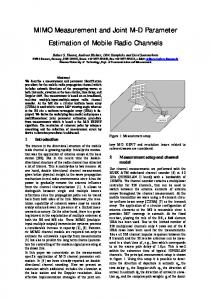
Fig. 1: Measurement scenario for 5-D channel sounding.
2 Channel model From ray tracing modeling it is well known that even complicated wave propagation phenomena in a continuum of reflecting, diffracting and scattering objects can be modeled by a superposition of plane waves. The method is based on geometric optics and the accuracy can be controlled by the number of rays used. However, the high computational effort and the necessity of detailed site-specific geometrical information make ray tracing models difficult to use. If we apply the idea of determinis-
VTC 2001-Spring, Rhodos, May 6-9, 2001
tic plane wave modeling to measurement based modeling, these disadvantages can be avoided. For model parameter estimation we end up in a R-D harmonic retrieval problem which can be very effectively solved by subspace based parameter estimation methods. In the following we consider a finite sum of discrete, locally plane waves. This means that along the aperture of the receiving and transmitting antennas, the wavefronts are plane. We further assume that the relative bandwidth is small enough so that the time delay of the impinging waves simply transforms to phase shifts between individual antennas of the arrays and the array aperture is small enough that there is no observable magnitude variation of any single wave received at different elements. Furthermore, the time delay τp of wavefront p, its angle of arrival AoA at the receiver ϕRp, θRp, angle of departure AoD at the transmitter ϕTp, θTp, and Doppler shift αp are supposed to be time invariant during a measurement snapshot time interval which is used to estimate one set of channel parameters [6]. The measurement time interval is given by the number of channel impulse response vector snapshots (CRVS). In complex envelope notation we define the basic signal model as: P
h (α, τ, ϕ R , θ R , ϕ T , θT ) = ∑ γ p δ (α − α p ) δ (τ − τ P )
(1)
p =1
⋅ δ (ϕ R − ϕ RP ) δ (θ R − θ RP ) δ (ϕT − ϕ TP ) δ (θT − θTP )
(1) gives the complex multipath channel impulse response representation in 6 dimensions for both directions seen from Tx and Rx, time delay and Doppler frequency shift. Mostly, γp is considered as fast fading since with a limited receiver resolution there is a superposition of not resolved paths. These paths add up with different (time varying) phase shifts causing fast fading of complex impulse response (CIR) taps. It is well known that a wide measurement bandwidth reduces fading essentially. However, directional resolution gives even more potential to resolve multipath. This is especially true in case of double directional resolution since this may resolve local scattering at the MS position which otherwise can not be resolved from the BS position (Fig. 2). Therefore, with high resolution, both in terms of the individual parameters as well as with respect to the number of resolved parameters, for a short observation time, γp can be considered as time invariant. Note that the deterministic time variation of the path phases is contained in the Doppler shift parameter. MS + local scattering
BS
Fig. 2: MS surrounded by local scatterers.
3 Measurement setup As described in [6], an effective single-input-multipleoutput (SIMO) channel sounding device relies on periodic multifrequency excitation signals, real-time sampling and correlation processing. Unlike the well-known sliding correlation sounder principle, no surplus measurement time is needed and the highest possible measurement repetition rate for a channel with a maximum path excess time delay τmax can be achieved, which is 1/τmax. Its lower limit is given by the Doppler bandwidth Bmax which determines the Nyquist sampling frequency of the fast fading CIR taps. Since the delay-Doppler spreading factor S = τ max ⋅ Bmax of typical mobile radio channels is well below 1%, fast sequential acquisition of the antenna outputs is possible for real-time recording of the SIMO CIR in case of reasonable array dimensions. The recorded signal vector consists of integer periods of the received excitation signal response. Obviously, the angular resolution capability of SIMO channel sounding is limited to the AoA dimension at the Rx only since the AoD is not resolved. At the Tx playing the role of the mobile station (MS) typically omnidirectional antennas are used. This limitation of SIMO channel sounding can be overcome by a MIMO extension which includes multiple antennas at the transmitter as well. For that purpose the proved sequential Rx antenna acquisition principle is extended by sequential emission of the periodic multifrequency excitation signal from the multiple Tx antennas. Synchronous switching at the Rx and the Tx requires initial timing and switching frame synchronization which has to be maintained over the complete measurement time even in case of remote operation of Tx and Rx. This is accomplished by Rubidium reference synchronization. The total snapshot time length now is roughly given by ts = 2τmax MTx MRx, with the number of the antennas MTx and MRx at the Tx and the Rx site, respectively. The factor of two results from the one period blanks inserted at the receiver after every period to remove switching transients. This all sets the limits on the max. Doppler bandwidth which has to be smaller than 1/ts. Our channel measurements are performed with the RUSK ATM wideband channel sounder [6] at 5.2 GHz (HIPERLAN II band) with a bandwidth of 120 MHz. The channel sounder contains a multiplexer controller for 256 channels, that can be used to switch between the antenna elements of the antenna arrays throughout the channel measurement. At the mobile transmitter a 8-element circular uniform beam array [8] has been used as the transmit array. The application of a circular configuration of antenna elements at the MS is reasonable since it provides 360° coverage in azimuth. At the fixed receiver, playing the role of the BS, an 8 by 8 element URA has been used.
VTC 2001-Spring, Rhodos, May 6-9, 2001
Due to the limited number of 256 multiplexer channels only 4 rows out of the 8 URA rows have been used for the measurements. The spacing between the URA rows is 0.4943 ⋅ λ c and between the URA columns 0.4943 ⋅ λ c , the wavelength of the carrier frequency was λ c = 5.77cm . Using the measurement setup described, it is possible to determine the direction of departure in azimuth ϕTp, the time delay τp, the Doppler shift αp, the direction of arrival in azimuth ϕRp, the direction of arrival in elevation θRp, and the complex path weights γp of the dominant components P of the narrowband multipath radio channel. The measured data of the multipath channel can be represented using the following data model.
H (ν (1) ⋅ t 0 , ν ( 2 ) ⋅ f 0 , ν ( 3) ⋅ s r , ν ( 4 ) ⋅ s c , n (5 ) ⋅ ϕT 0 ) = P
⋅ ∑ γ p ⋅cT (n (5) ⋅ ϕT 0 − ϕTp ) ⋅ c R (ϕ Rp , θ Rp )
(2)
p =1
⋅ e − j2π (ν ⋅t0 ⋅α p + ν ⋅ f 0 ⋅τ p + ν ⋅sc ⋅sin (ϕRp )cos (θ Rp )+ ν ⋅sr ⋅sin (θRp )) . The variables n (i ) respectively ν (i ) represent a point in the 5-D sampling grid. The values t 0 , f 0 , s c , s r , and ϕT0 describe the equidistant 5 dimensional sampling grid of the measurement. The functions cT (ϕT ) and c R (ϕ R , θ R ) describe the beam pattern of a single element of the Tx and the Rx antenna array respectively. Using the DFT along the fifth dimension n (5 ) ⇒ ν (5 ) and lc = 1 (2π) (2) yields H (ν (1) ⋅ t 0 , ν ( 2 ) ⋅ f 0 , ν (3 ) ⋅ s r , ν ( 4 ) ⋅ s c , ν (5 ) ⋅ l c ) = g T (ν (5) ⋅ l c ) (1)
(2)
(3)
(4)
P
⋅ ∑ γ p ⋅c R (ϕ Rp , θ Rp ) p =1
⋅ e − j2π (ν ⋅t0 ⋅α p + ν ⋅ f 0 ⋅τ p + ν ⋅sc ⋅sin (ϕ Rp ) cos (θ Rp )+ ν ⋅sr ⋅sin (θ Rp )+ ν ⋅lc ⋅ϕTp ) , with the DFT of cT (n (5 ) ϕT 0 ) = g T (ν ( 5) ⋅ l c ) . This equation shows that the estimation of the 5 model parameters ϕTp, τp, αp, ϕRp, and θRp is a 5-D harmonic retrieval problem that can be solved using the M-D Unitary ESPRIT algorithm with a very reasonable effort. (1 )
(2)
(3)
(4)
( 5)
4 Joint channel parameter estimation using the M-D Unitary ESPRIT In order to estimate the parameters of the dominant multipath components of our channel model using the 5-D Unitary ESPRIT algorithm [9] we have developed an algorithm to transform the measured CRVS into (2) using the ideas in [3]. Since the channel sounder measures in the time domain, the data are transformed into the frequency domain using a FFT. Afterwards the frequency responses are calibrated using the known measurement system frequency response, thus reducing the influences of the channel sounder components to the measurement
results. Furthermore the non ideal characteristics of the URA are reduced by application of a calibration matrix, detailed information about a well-suited URA calibration algorithm can be found in [7]. Since the CUBA applied at the Tx is working in the beam space the data must be transformed from the beam space into the ESPRIT data space, this can be done by using a Fourier-transform and an equalization with the Fourier-transformed beam pattern of a single CUBA antenna element. For further details on direction estimation using a CUBA in conjunction with the Unitary ESPRIT see [3], [5]. With these three main calibration and transformation steps the measured data set H M1×M 2 ×…×M 5 is ready for parameter estimation using the M-D Unitary ESPRIT. The sizes of H are determined by the number of frequency bins ( M 1 ) , number of Rx URA rows ( M 2 ) and columns ( M 3 ) , virtual aperture size of the Tx CUBA ( M 4 ) , and number of consecutive channel snapshots taken over time ( M 5 ) . Beneath the data transformation and calibration steps needed for the M-D Unitary ESPRIT application a further preprocessing step is required. Obviously only a single snapshot of the radio channel can be measured at one particular time, but for parameter estimation using ESPRIT type algorithms the signal subspace must be estimated using an eigenvalue decomposition of the data covariance matrix. But for the estimation of the data covariance matrix multiple independent measurements of the “same” radio channel are required. This implicates varying path weights with static time delays, static Doppler shifts, and static angles what is simply an antagonism. An effective solution of this problem is given by the so-called subspace smoothing technique [4], [9]. The idea is to reduce the measured aperture in all dimensions of the R-D aperture to smaller sizes (N1 … NR). The measured snapshot of the full R-D aperture provides then many overlapping smaller snapshots L1 × L2 × … × LR , with Li = M i − N i + 1 , of the reduced M-D aperture. An optimal choice of Ni is given by N i = 2 3 ⋅ M i + 1 , providing the best trade off between the reduced aperture size and the rank improvement of the covariance matrix, respectively the signal subspace [4]. For the 1-D up to the 3-D ESPRIT algorithm and moderate aperture sizes this smoothing step can be explicitly implemented. That means, using the selection matrices J lR ,…,l1 a matrix Yss is created containing all measurements of the reduced aperture size Yss = [J 1,…,1 x J 1,…, 2 x … J LR ,…, L1 x] , with x = vec{X} . For Unitary ESPRIT application the complex valued data matrix Yss is subsequently transformed into a real valued H Yss } Im{Q HMu Yss }] . For data matrix A using A = [Re{Q Mu the definition of the selection matrices J lR ,…,l1 and the matrix Q Mu used throughout the Unitary ESPRIT see [9]. For M-D ESPRIT applications this direct implementation
VTC 2001-Spring, Rhodos, May 6-9, 2001
of the subspace smoothing step is unsuitable, since the complex valued input matrix of size R
2 ⋅ ∏ M r grows to a real matrix r =1
R
∏N r =1
R
r
by 2 × ∏ Lr . r =1
Therefore a signal subspace estimation algorithm without the explicit generation of the matrix A has been developed. The algorithm uses the ARPACK which is a FORTRAN library for the estimation of some eigenvalues and eigenvectors of large matrices using Arnoldi-iterations [10]. This package has 3 main advantages for the implementation of the signal subspace estimation step. Firstly the number of eigenvectors or singular vectors needed for the description of the signal subspace related to the dominant propagation paths is very small compared to the size of the data matrix A, some 10 out of some hundreds or thousands. That means in terms of the M-D Unitary ESPRIT only the singular vectors belonging to the largest singular values of A must be calculated, what is possible using the ARPACK as stated before without loss of accuracy. Simultaneously the computational costs are reduced, since the number of iterations is proportional to the number of eigenvectors to be computed by the ARPACK. For channel sounding data the number of iterations is typically 4-10 times the number of eigenvectors requested. Secondly for the Arnoldi-iterations implemented in ARPACK only the product between a vector v i and the data y i = A T ( Av i ) must be calculated in every iteration step. Since the product w i = Av i and y i = A T w i can be effectively implemented using only the measured data X and not the full matrix A a huge amount of physical memory needed for the storage of A is saved. Thirdly, there exists a parallel version of ARPACK the so-called PARPACK that opens a way for the computation of the signal subspace estimation step on multiprocessor systems. The user must only provide an implementation of the two vector products mentioned above, what can be implemented in an efficient way on multiprocessor systems and only parts of the vectors v i , w i , y i , and of the data X must be distributed between the processors. For the implementation one should furthermore take into account that the non square matrix A has approximately 2 R −1 times more rows than columns, where R is the number of dimensions of the data space X. Therefore it may be computational effective to calculate the eigenvalue decomposition of A T A = VΣ 2 V T revealing the right singular vectors V of A or, if the ARPACK is used, some of the right singular vectors Vs belonging to the P largest singular values of A and to calculate the left singular vectors spanning the signal subspace E s using E s = U s Σ s = AVs .
The subsequent steps of the M-D Unitary ESPRIT, the set up and solution of the R invariance equations using a LS, TLS, or SLS approach, the joint diagonalization using the Simultaneous Schur Decomposition of multiple non symmetric matrices, and finally the estimation of the path weights γp related to the estimated propagation path parameters can be implemented in the usual way [9],[3].
5 Measurement Results The following parameter estimation results were obtained from measurements in an inner court yard. At three sides the court is bordered by three-storied office buildings and at one side it is open. The measurement trolley with the Tx-CUBA was moved from point 1 to point 5, and the Rx URA was installed 9.40 meter above ground in an open window (see Fig. 1). Every 250 ms a channel snapshot has been taken, the total measurement time was 137 seconds yielding an amount of 547 snapshots. After the calibration and transformation steps described in section 4 the total amount of data was 193 measured frequencies times 4 URA rows times 8 URA columns times 5 virtual aperture values of the CUBA times 547 channel snapshots over time. For the 5-D Unitary ESPRIT parameter estimation 2 consecutive channel snapshots have been used for Doppler resolution yielding 546 overlapping data sets X193×4×8×5×2 . After the parameter estimation using the 5-D Unitary ESPRIT 546 different parameter sets were available. Using the information about the Rx-URA position, the estimated path delays, the azimuth of arrival, and the elevation of arrival, the position of the 3 strongest sources in the measurement scenario have been reconstructed. The strongest path was the LOS path describing directly the position of the measurement trolley. The weaker ones are virtual sources produced by reflections on ground, the surrounding walls, the person pulling the trolley, and so on. The dominating sources estimated are plotted for all 546 measurements in Fig. 4 as dots, stronger paths are plotted in a darker color. Since only a subset of the 7 parameters of every path estimated can be depicted in Fig. 4, Fig. 3 shows 6 parameters of the LOS path omitting the phase of the path weight. To demonstrate the performance of the Doppler estimation step the relation between the path delay variation and the Doppler shift d τ (t ) ⋅ f c = α (t ) dt has been used to calculate the path delay from the estimated Doppler values using the equation t n τ (n ⋅ t s ) = s ∑ α (n ⋅ t s ) + τ 0 . f c i =0
VTC 2001-Spring, Rhodos, May 6-9, 2001
The remaining unknown value τ 0 has been calculated using the estimated time delays of the LOS path. Both, the estimated time delay and the time delay calculated from the estimated Doppler shifts are shown in the upper plot of Fig. 3, they match very well to each other. The path weight of the LOS shows a small drop around point 2 what can be explained by the leafs of the tree obstructing the LOS in this section of the measurement drive (see Fig. 1). For the representation of the AoD in azimuth the orientation of the trolley within the court yard in the four main sections of the measurement drive (1-2, 2-3, 3-4, and 4-5) has been taken into account, making the comparison between AoD and AoA in azimuth possible. The difference between both is approx. 180° at all positions fitting to the expectations for this scenario. Altogether these first results show, that at least the estimation of the 7 parameters of the dominant propagation paths is feasible using MIMO channel sounder measurements of the mobile radio channel. With the implementation proposals in section 4 the parameter estimation using the M-D Unitary ESPRIT is possible in a reasonable time (some hours for 500 snapshots) using today’s computers.
Doppler frequency [Hz] angle [deg]
path weight [dB] time-delay [ns]
1
2
3
4
5
time-delay estimation
90 80 70 60
derived from the Doppler estimation
-50 -60 -70 50 0 -50 -100
Rx-AoA in azimuth Rx-AoA in elevation Tx-AoD in azimuth
5 0 -5 0
20
40
60 time [s]
80
100
120
Fig. 3: Estimated time delays, angles, Doppler shifts, and path weights of the LOS-path.
6 Acknowledgements This work was partly supported by the German Federal Ministry of Education, Science Research and Technology under the ATMmobil project line and by the DFG within the AKOM focus project. The authors wish to thank MEDAV GmbH for the cooperation in designing the RUSK MIMO vector radio channel sounder, to IHE (Uni-
versity of Karlsruhe), and to IRK Dresden both for cooperation in antenna design. 3
4
2
5 1
y 5m
x Rx-URA
Fig. 4: Estimated positions of the 3 dominating sources.
References [1]
G. J. Foschini and M. J. Gans, “On the limits of wireless communications in a fading environment when using multiple antennas,” Wireless Personal Communications, vol. 6, pp. 311-335, 1998. [2] M. Steinbauer, A.F. Molisch, A. Burr, R. Thomä,” MIMO channel capacity based on measurement results,” ECWT 2000, Oct. 2-6, Paris. [3] A. Richter, D. Hampicke, G. Sommerkorn, and R. S. Thomä, “Joint Estimation of DoD, Time-Delay, and DoA for High-Resolution Channel Sounding,” VTC 2000s, Tokyo, May 15-18, 2000. [4] S.U.Pillai, “Array Signal Processing”, Springer-Verlag New York Inc., 1989, pp. 47-59 [5] A. Richter, R.S. Thomä, “CUBA-ESPRIT for Angle Estimation with Circular Uniform Beam Arrays,” Proc. of Millennium Conf. On Antennas and Propagation, Davos, CH, April 9-14 2000. [6] R. Thomä, D. Hampicke, A. Richter, G. Sommerkorn, A. Schneider, U. Trautwein, and W. Wirnitzer, “Identification of Time-Variant Directional Radio Channels,” IEEE Trans. Instrumentation and Measurement, vol. 49, pp. 357-364, 2000. [7] G. Sommerkorn, D. Hampicke, R. Klukas, A. Richter, A. Schneider, and R. Thomä, “Uniform Rectangular Antenna Array Design Issues for 2-D ESPRIT Application”, Proc. EPMCC 2001, Session 13 “Smart Antennas” [8] F. Demmerle, W. Wiesbeck, “A biconical multibeam antenna for space-division multiple access,” IEEE Transactions on Antennas and Propagation, vol. 46, pp. 782787, June, 1998. [9] M. Haardt, “Efficient One-, Two-, and Multidimensional High-Resolution Array Signal Processing,” Ph.D. Thesis, Shaker Verlag, Aachen, Germany, 1996. [10] http://www.netlib.org/scalapack