Available online at www.sciencedirect.com
ScienceDirect Procedia CIRP 36 (2015) 83 – 88
CIRP 25th Design Conference Innovative Product Creation
MINARGUS: Test tool for User Experience measurement and parameter modification within ADAS simulation Maik Aurichta*, Rainer Starka * a Technische Universität Berlin, Pascalstraße 8-9, 10587 Berlin, Germany
* Corresponding author. Tel.: +49 030 39006 111;
[email protected]
Abstract Advanced Driver Assistance Systems play a leading role in the revolution of vehicles; it has become a high priority for automotive industry and meanwhile is used in all automotive segments. In this paper, a tool is introduced, which allows capturing User Experience (UX) on the M odelin-the-Loop level (where only abstract models exist): M INARGUS. This solution allows direct feedback to other partners in the development process and, hence, allows a more efficient work relationship between system development engineers and test & validation engineers. The tool allows a connection between a simulation model and the measurement of physiological data in one environment. The Traffic Jam Assist system is used as an ADAS example in this paper. © © 2015 2015 The The Authors. Authors. Published Publishedby byElsevier ElsevierB.V. B.V. This is an open access article under the CC BY-NC-ND license Peer-review under responsibility of the scientific committee of the CIRP 25th Design Conference Innovative Product Creation. (http://creativecommons.org/licenses/by-nc-nd/4.0/). Peer-review under responsibility of the scientific committee of the CIRP 25th Design Conference Innovative Product Creation Keywords: Advanced Driver Assistance Systems; Validation; User Experience
1. Introduction „Dig ital networking is a revolution around the car and the entire transport system. Co mmunication and information are becoming increasingly important. The exchange of in formation of all road users to each other and networking with the internet are major steps forward towards resource and time-saving traffic of the future.” [1] Advanced Driver Assistance Systems are important in this revolution; it has become a high priority for the automotive industry. Current systems still lack robustness and error free capabilit ies which negatively influence customer satisfaction. The errors vary fro m either co mpatib ility problems between different systems to general runtime errors. However, one can also recognize dissatisfaction within different assistance systems. It may influence usability or even User Experience (UX) for various reasons (e.g. symbolic aspects, subjective feelings, habits). Within the development o f Advanced Driver Assistance Systems, these motivations are tested continuously. The validation starts with a model-in-the-Loop (MiL), and ends with the Vehicle-in-the-loop (ViL), shortly after the physical testing process begins (driving tests, field
tests, etc.). In this paper, a tool is to be introduced, which allo ws to capture the UX already on MiL level to be fed back directly into the develop ment process. This tool allo ws for a more efficient work relationship between system develop ment engineers and test & validation engineers. Moreover, within the last 10 years, product development processes have changed significantly. The t ime-to-market has been decreased [2], the number of functionalit ies of a product has been raised, the portfolio of co mpanies has been changed in terms of mo re variants [3] and with that, the co mp lexity of the development has been increased [4]. In the end, the product has to satisfy customer demands. There are several validation cycles within the development process to make sure, the right product is being developed in terms o f intended purposes of the customer. Beyond that, there are also verification cycles to make sure the requirements of the customer are fu lfilled. The user experience needs to be taken seriously in order to fulfill the customer requirements.
2212-8271 © 2015 The Authors. Published by Elsevier B.V. This is an open access article under the CC BY-NC-ND license (http://creativecommons.org/licenses/by-nc-nd/4.0/). Peer-review under responsibility of the scientific committee of the CIRP 25th Design Conference Innovative Product Creation doi:10.1016/j.procir.2015.03.063
84
Maik Auricht and Rainer Stark / Procedia CIRP 36 (2015) 83 – 88
2. 2. State of the Art 2.1. Advanced Driver Assistance Systems The driver’s primary task, relating to road transport, is to have control over the car while safely navigating the road. Due to the increasing co mplexity o f the resulting tasks, the driver can quickly reach physical and mental limits. Fro m these factors, the most important functions can be derived to ensure the safety of the people inside (driver, passengers) and outside (pedestrians) the car. In this case the human being is the biggest and most unpredictable risk factor in itself. As a result the human being is also a main focus of the development of Advanced Driver Assis tance Systems. Especially driver performance relative to driving a car relat ing to road transport must be considered as a starting point. In this perspective the driver is viewed not as a single factor but represents a dynamic factor embedded in the overall system and the environment. The basic system configuration is the same for all Advanced Driver Assistance Systems and corresponds to a typical mechatronic system. The basis is always its mode of action, wh ich can be: pneumatic, hydraulic, mechanical or electro mechanical. In the first place the system receives state variables of a certain part of the system, which is realized by a physical or virtual sensor. In addit ion to the vehicle -related variables, sensors are used to record certain informat ion fro m the environment. With a control unit the in formation is processed and evaluated. The actuators are then set to the desired change in the previously recorded state variable. Between these co mponents there are certain transport mechanis ms, info rmation, energy and mass transfer flow by which the communication takes place. The basic system provides informat ion about all three flow types. The contact between the sensors and actuators are connected digitally via an informat ion processing module, accordingly, there is only one flow of info rmation. The informat ion processing element is often still associated with information processing elements of other Advanced Driver Assistance Systems over a digital communicat ion interface. Thus, different info rmation can be worn together and included for the proper response of the actuator. The Traffic Jam Assist is an intelligent form of cruise control that slows down and speeds up automatically to keep pace with the car in front of the own, especially in t raffic jam. The Traffic Jam Assist consists of a longitudinal and a transverse guide assistant. The longitudinal co mponent of the Traffic Jam Assist system consists of an automatic d istance control and an automatic stop & go system. It has basically the same system limits as the two single systems. Therefore the Traffic Jam Assist cannot provide automatic driving in every situation. In certain situations, the driver receives a takeover pro mpt. A lso, the driver must confirm the setting off fro m standstill. As an extension to the ACC Stop & Go is the assumption that large stationary targets can be detected by sensors. The transverse component of the Traffic Jam Assist system is to be limited to the low-speed range. In order not to
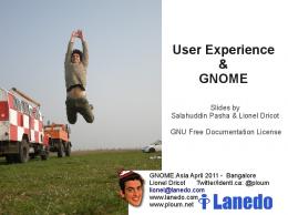
provide the functionality of an autonomous city vehicle to the driver, the lateral control is available only under 40 km/h. In addition, the maximu m steering angle is limited. If the situation requires a higher steering wheel angle, the driver receives a take-over pro mpt [5]. Figure 1 shows the basic functionality of the system including the different sensors such as camera, ultrasonic and lane keeping assist.
Figure 1: T raffic Jam Assist [6]
2.2. Validation methods for ADAS Validation is the central activity of the product development process and therefore has a high relevance [7]. Mostly used in early phases are virtual prototypes such as Dig ital Mock-ups (DM U’s). A limitation of the v irtual environment, however, is the lack of tactile feedback. An object in the virtual world cannot be compared with the feeling of a real feedback in co mbinat ion with the hand-eye coordination [8]. Only in the advanced phases of the product development process physical prototypes are built. As the overall integration and validation takes place predominantly at this late stage, the rectification of errors is usually associated with high costs and high effort [9]. The combination of dig ital prototypes with physical elements to realize real-time force feedback interaction is relatively new. There are different approaches within this field. Bordegoni et.al. for examp le, describe a framework for applications using mixed prototyping and Mixed Reality techniques. Therefore the Virtual Reality environ ment is enriched with physical elements (switches, buttons or other mock-ups). Hereby it is possible to evaluate for instance the ease of use, sensorial feedback or accessibility [10]. Within the development of Advanced Driver Assistance Systems there are different validation methods. The Model-inthe-loop (MiL) test is one of the first validation methods which will be conducted. MiL allo ws tests without the investment of hardware. M iL refers to a process in which an
Maik Auricht and Rainer Stark / Procedia CIRP 36 (2015) 83 – 88
embedded system connects via its inputs and outputs to a matched counterpart system. In this case, tests can be conducted any number of t imes with d ifferent parameters. Also the use of data fro m real tests will be applied in p ractice. In later stages Software-in-the-loop (SiL), Processor-in-theloop (PiL) and Hardwa re-in-the-loop (HiL) tests are used. During the SiL, the model of the MiL test is converted into Ccode and will be tested in an environment. In the early testing phases driving simulators are used in some cases. The maturity of the simulator (in terms of degrees of freedo m, visualizat ion, haptics, sound etc.) increases with the maturity of the model which needs to be tested. Within MiL, the models are mostly tested in a simple environ ment with basic controls such as a steering wheel, pedals and a monitor. Nevertheless most tests are only plausibility checks without a driver in the loop. In the ending phases, sophisticated simulators are in operation, which are able to reproduce G-forces. 2.3. User Experience The haptic perception together with visual perception is an important part in build ing a mental model of the product to the user [11]. The tangible interaction with the prototype is a part of the User Experience (UX) concept. This can be understood as an umbrella term for various design and usability disciplines [12]. “By “experience” we mean all the aspects of how people use an interactive product: the way it feels in their hands, how well they understand how it works, how they feel about it while they’re using it, how well it serves their purposes, and how well it fits into the entire context in wh ich they are using it.” [13]. Research has shown that factors such as particular emotions (e.g. subjective feelings, physiological reactions), usability (e.g. effectiveness, learnability) and aesthetic aspects (e.g. visual, haptic) are play ing a major role in the evaluation of products and product characteristics [14]. UX methods are usually used in the later phases. The integration in early phases is not being used yet. Where the classic usability refers to the objectivity of the user, the UX expands this approach. One tool for measuring the UX is the questionnaire AttrakDiff. The questionnaire goes beyond usability and considers aspects such as job satisfaction, attractiveness or the hedonic quality (stimulation, identity).
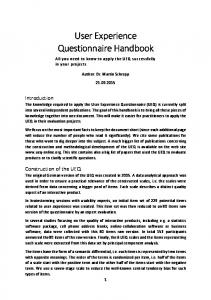
dimensions. The research focus is directed on the product development and manufacturing process, focusing particularly on the user-centered product design and improvement of the interface between humans and technology [15]. Due to their low purchase price, static driving simu lators can be quickly assembled and disassembled in order to ensure a fast evaluation depending on the application requirements. A major disadvantage of static driving simulator is the so -called simu lator sickness. The simulator sickness occurs in about 2040 % of all users. It is very similar to the mot ion sickness [16]. Dynamic simu lators also reproduce vehicle acceleration, rotations as well as other movements. Therefore mot ion systems are used (e.g. hexapod systems). The dynamic d riv ing simu lator of Daimler A G in Sindelfingen for example started its operations in October 2011 and is now one of the most advanced of its kind and consists of a dome with 360 ° visualizat ion by both mock-ups and a complete vehicle that can be installed. The do me and the motion p latform are mounted on a twelve-meter long rail for translational mot ion simu lation that moves the system with up to 12 meters per second [17]. In the early phases the static simulators are often used because of the operation costs and because they are appropriate for most of the testing purposes. Figure 2 shows different driv ing simulators of Automotive OEM as well as from suppliers and Research Institutes.
2.4. Driving simulators Static driv ing simulators are suitable when the subjective impressions of the dynamics are not important. They are usually lo w cost and compact in dimensions. They are used for studies in wh ich the dynamics play a subordinate role. The Usability Research Simulator (URS) at the Chemnit z University for examp le is a modular, portable static driv ing simu lator. In addition to a 180 degree vision system, it consists of an alu minum profile structure for simu lating the passenger compart ment, which is changeable in its
Figure 2: 1: Festo Airmotion Ride [18]; 2: Force Dynamics 401 [19]; 3: Digital Cube T est Center (T echnische Universität Berlin) [20]; 4: DLR Dynamic Driving Simulat or [21]; 5: T oyota Driving Simulator [22]; 6: Daimler Driving Simulator [17]
85
86
Maik Auricht and Rainer Stark / Procedia CIRP 36 (2015) 83 – 88
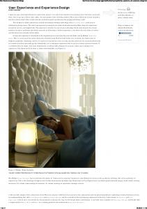
3. Motivati on The increase of computer technology in recent years facilitates more virtual testing. The hu man as a test object is integrated too late in the development process. The variety and quantity of assistance systems in a car lead to new problems which not only consist of Usability issues but also of UX. Thus, there must be a change in the development of mechatronic systems especially to consider UX in early phases of the development process. To support the change of the development process the Informat ion Technology needs to provide innovative tools. 4. MINARGUS * : A new tool to measure User Experience online Within experiments during a validation cycle (see chapter 2.2. Validation methods for ADAS) the user performs different tasks through a virtual wo rld and experiences th e movements, visualization and sounds from the simu lation via suitable output channels (hexapod seat, 3D project ion, and surround sound). The driver will be tracked through various channels: pulse, ECG, EEG, eye tracking, cameras, sound, input devices, etc. In order to track all changes and its effects directly, a new tool will be developed: MINA RGUS (see Figure 3). On the one hand MINARGUS allows the visualizat ion of all measured data and on the other hand it allo ws the direct parameter sweep. Therefore, the tool is directly connected to the simulation model. If the developer makes changes to certain pre-defined parameters, the effect can be viewed directly in MINARGUS. The advantage over individual tests with questionnaires is that several changes can be made within one experiment. Now the developer can draw direct conclusions and can optimize the parameter. The tool is developed in Matlab/Simu link and therefore allo ws a direct connection via Matlab to the simulat ion environment (see Figure 3 (1)) such as dSpace Automotive Simu lation Models (ASM) [23], IPG Carmaker [24], Dy mola and others. The connection can be realized either via Matlab or the FMI Standard (Functional Mockup Interface [25]). On the other side, the tool is connected to the User Tracking Environment (2). Th is environment consists of a psychological measurement system (PAR-Port (3)) with several inputs such as EEG, EKG, EOG, ECG, Pu lse. The system interacts via Mat lab with MINA RGUS. Furthermore it has a connection to different streams (video fro m the EyeTracking system and cameras, audio) as well as the satisfaction buttons which are located on the steering wheel. During a test, the operator requests the user to press either the “satisfied” button or the “dissatisfied” button on the steering wheel which are supposed to indicate the users experience in different situations. Those are tracked in MINARGUS.
*
MINARGUS = Minerva (Roman goddes of wisdom) + Argus Panoptes (Greek mythology: 100-eyed giant)
Within the tool the user can choose between those different channels, depending on the test case (e.g. EEG, Sat isfaction buttons, pulse) (4). Aside fro m the fact that the tool has the standard functionalities (save, open, ju mp to t imes, etc.) (5,6), it allo ws the direct parameter change within M INA RGUS (7). Thus, the user doesn’t need to switch between tools and simu lation environ ments. By changing parameters (for example the starting delay) the user can see the influences via the different channels. Developers, test persons and experimental designer are now working very closely together, to minimize the number of iteration cycles and time. The development environ ment has to become a test environ ment and vice versa. The new working areas need to be fle xib le, small and inexpensive, so that many tests can be performed. In industry driving simu lators are usually both very large and expensive to purchase and operate and usually fully booked. Such a new working area is currently being built up at the Technis che Universität Berlin under the title DCTC: Digital Cube Test Center. Fo r this purpose a test center is built, wh ich is an environment for both developers and experimental designer. The attempt of the test center is to be small, flexible and inexpensive. The core is an active driving simu lator (hexapod system + mot ion platform for 6 degrees of freedom), a 360° active stereo visualization and a surround audio system [26]. 5. Conclusion and Outlook The proposed tool and its sub-projects (such as the development of a robust process and methods for the application) are currently being developed. The tool shall be validated at the end with a study consisting of > 30 participants. Hereby the test persons will drive a defined test scenario. During the test the operator changes parameters (such as starting acceleration or the starting delay (see chapter Advanced Driver Assistance Systems ) on the fly. The measured data (such as EEG, ECG, pulse, etc.) can then be evaluated in real-t ime to optimize the parameters. Therefore two different sets of parameters will be co mpared to each other by using also questionnaires (e.g. AttrakDiff, meCue). The results will be published at the end of 2015. Furthermore the interfaces of the tool shall be extended. One example is the Functional Mockup Interface (FMI). Acknowledgements The authors thank the European Regional Develop ment Fund (EFRE) for supporting the research project FORUM “Forschungs- und Anwendungszentrum für Füge- und Beschichtungstechnik”.
Maik Auricht and Rainer Stark / Procedia CIRP 36 (2015) 83 – 88
Figure 3: T he GUI of MINARGUS (work in progress)
87
88
Maik Auricht and Rainer Stark / Procedia CIRP 36 (2015) 83 – 88
Re fe rences [1] [2] [3] [4]
[5]
[6]
[7] [8] [9] [10]
[11] [12]
[13]
VDA, Annual Report 2013, 2013, www.vda.de/en/downloads/1182/. K.B. Kahn, T he PDMA Handbook of New Product Development: Second Edition, John Wiley & Sons, 2004. G. Schuh, U. Schwenk, Produktkomplexität managen, Hanser, München, 2001. U. Lindemann, M. Maurer, T. Braun, Structural Complexity Management: An Approach for the Field of Product Design, Springer Berlin Heidelberg, Berlin, Heidelberg, 2009. T . Schaller, J. Schiehlen, B. Gredenegger, Stauassistenz – Unterstützung des Fahrers in der Quer- und Längsführung: Systementwicklung und Kundenakzeptanz, in: 3. Tagung Aktive Sicherheit durch Fahrerassistenz, 2008. Bosch Mobility Solutions, Driver assistance systems: past, present and future: Driver assistance systems: milestones and objectives, 2014, http://www.bosch-mobilitysolutions.com//en/de/specials/specials_safety/automated_driving/techn ology_and_development_1/driver_assistance_systems_88/driver_assis tance_systems_89.html, accessed 2 January 2015. A. Albers, Five Hypotheses about Engineering Processes and their Consequences, in: Proceedings of the TMCE, Ancona, 2010. G. Fadel, D. Crane, L. Dooley, R. Geist, A link between virtual and physical prototyping, 1995. F.-L. Krause, H.-J. Franke, J. Gausemeier, Innovationspotenziale in der Produktentwicklung, Hanser, München [u.a.], 2007. M. Bordegoni, U. Cugini, G. Caruso, S. Polistina, Mixed prototyping for product assessment: a reference framework, in: Int J Interact Des Manuf, 2009, pp. 177–187. E.B. Goldstein, M. Ritter, G. Herbst, Wahrnehmungspsychologie, 2nd ed., Spektrum, Akad. Verl., Heidelberg [u.a.], 2002. A. Cooper, R. Reimann, D. Cronin, About face: Interface- und Interaction-Design ; [die Ziele und Erwartungen Ihrer User untersuchen und verstehen ; die Methode des Goal-Directed-Designs anwenden ; Produkte entwickeln, mit denen Ihre User optimal interagieren können], 1st ed., mitp, Heidelberg, München, Landsberg, Frechen, Hamburg, 2010. L. Alben, Quality of experience: defining the criteria for effective interaction design, interactions 3 (1996) 11–15.
[14] S. Mahlke, User Experience of Interaction with Technical Systems: T heories, Methods, Empirical Results, and their Application to the Development of Interactive Systems. Dissertation, Berlin, 2008. [15] T U Chemnitz, Fahrsimulator, 2013, http://www.tuchemnitz.de/hsw/psychologie/professuren/allpsy1/verkehr/sim.php, accessed 6 November 2013. [16] D.M. Johnson, Introduction to and Review of Simulator Sickness Research, 1832nd ed., Alabama, USA, 2005. [17] Daimler, Driving simulator in Sindelfingen: Investment in cuttingedge technologies, 2013, http://www.daimler.com/technology-andinnovation/insights-into-research-and-development/driving-simulator, accessed 2 January 2015. [18] Festo, Airmotion_ride, 2011, http://www.festo.com/cms/de_corp/9788.htm, accessed 2 January 2015. [19] Force Dynamics, Force Dynamics 401, 2009, http://forcedynamics.com/401, accessed 02.101.2015. [20] M. Auricht, R. Stark, Digital Cube T est Center: Innovative Engineering & Interactive Experience, 2014, http://www.iit.tuberlin.de/fileadmin/fg126/DCTC.pdf., accessed 2 January 2015. [21] DLR - Institut für Verkehrssystemtechnik, Dynamic Driving Simulator, 2011, http://www.dlr.de/fs/desktopdefault.aspx/tabid1236/1690_read-3257/, accessed 2 January 2015. [22] T oyota, Pursuit for Vehicle Safety: Driving Simulator (Safety T echnology Innovation from a Driver's point of view), 2012, http://www.toyotaglobal.com/innovation/safety_technology/safety_measurements/drivin g_simulator.html, accessed 2 January 2015. [23] dSpace, Automotive Simulation Models, 2011, https://www.dspace.com/en/inc/home/support/suptrain/automotive_si mulation.cfm, accessed 2 January 2015. [24] IPG, Carmaker, 2011, http://ipg.de/en/simulationsolutions/carmaker/, accessed 2 January 2015. [25] Modelisar, FMI Support in Tools, 2013, https://www.fmistandard.org/tools. [26] R. Stark, Digital Cube T est Center: Innovative Engineering & Interactive Experience, 2013, http://www.iit.tuberlin.de/fileadmin/fg126/DCTC.pdf.