Contract. No. NAS1-19480. Februao'. 1997. Institute for Computer. Applications ... of parallel programming. .... While this places the burden on the programmer,.
/ NASA
Contractor
ICASE
Report
Report
201649
No. 97-8
LNNIVERSARY
MINIMIZING
OVERHEAD
ALGORITHMS
THROUGH
IN PARALLEL OVERLAPPING
COMMUNICATION/COMPUTATION
Arun
K. Somani
Allen
M. Sansano
NASA
Contract
Februao' Institute NASA
for
Operated
Space
NAS1-19480
Computer
Langley
Hampton,
National
No.
1997
VA
Applications
Research
in Science
and
Center
23681-0001
by Universities
Aeronautics
Space
and
Administration
Langley Research Center Hampton, Virginia 23681-0001
Research
Association
Engineering
Minimizing
Overhead
Overlapping
in Parallel
Algorithms
Through
Communication/Computation Arun {arun,
K.
Somani*and
allen}
M.
Sansano
@shasta.ee.washington.edu
Department University
Allen
of Electrical of Washington,
Seattle,
WA
Engineering Box
352500
98195-2500
Abstract One of the major goals in the design of parallel processing machines and algorithms is to reduce the effects of the overhead introduced when a given problem is parallelized. A key contributor to overhead is communication time. Many architectures try to reduce this overhead by minimizing the actual time for communication, including latency and bandwidth. Another approach is to hide communication by overlapping it with computation. This paper presents the Proteus parallel computer and its effective use of communication hiding through overlapping communication/computation techniques. These techniques are easily extended for use in compiler support of parallel programming. We also address the complexity or rather simplicity, in achieving complete exchange on the Proteus Machine.
*This research in part Contract No. NAS1-19480 and Engineering (ICASE),
supported by the National Aeronautics and Space Administration under NASA while this author was in residence at the Institute for Computer Applications in Science NASA Langley Research Center, Hampton, VA 23681. was
1
Introduction
1.1
Background
This
paper
presents
Proteus
[12], a parallel
communication/computation. communication started
overhead
in 1990
spare)
and
processor
is the world
machine
Intel
one
include The
processor
processor
was
the
The
result
costs
processor first
among the
When
a problem
serial
version,
overhead.
is added
nication
to be completed
a connection
possible
available
causes
for
ciencies can and data. Many
lead
general,
but
of time
data
serial
overhead
lacking
overlap
time
Overlapping
and
in the
following
would
have
through usually
the and
and/or
laying
the
hardware.
processor
communication and
computation.
data
buffer
waiting
as well.
This
to concentrate functions.
method
hardware on Proteus
low
scheduling
hardware
This
is not
additional
bulk tasks
the
minimize good
to approach a practical
to hide the
communicaare
technique
attempts
not ineffi-
resources
to
attempts
is
and
worse,
These
latency
overhead
provides
time
for communication
These
handles
Much
or
contention.
a
commu-
and
be slow,
and
computation
to invoke the
resources
protocols can
in the
is considered
call
resolved.
Inefficient link
found
Finally,
being
overhead.
is an This
a kernel
communication
partitioning
zero
at lower
time
by
For communication
to approach
Proteus processor.
communication
networks,
communication way.
system.
not
I/O
idle
with com-
on a node.
Allocating
latency.
problem
in the
cluster MAGIC
communication,
communication
pattern.
use of special
be servicing
communication
receiving
communication/computation
frees
This
interconnection
efficient
to reduce
processors
needs
link
Paragon + 1 com-
communication
to be transmitted.
to the
contention
per
the
node
processor.
communication/computation
data
processors
communication/computation
administration would
links,
employed
communication goal.
as low
processors
of the data.
due
the
processor
node
is initiated
the
processor for
utilizes
for a given
time.
and
a dual
a com-
commercial
an 8 processor
processors
sending
Also,
communicating
such
are
the
has
Stanford
inter-processor
to communication
amount
to the
the
transmission latency.
fast are
with
and contribute
techniques
protocols,
Then,
of Proteus
as a communication
Japan
among
execution
between
of longer
a given
communications
izable
routine.
management
is shared
processors'
from
[7] [6] at
was and
In the
releases
1 communication
utilizes
multiple
for
node
also
of overlapping
time
with
of
control
utilizing
do exist. time
effect
project
feature
architectures
Recent
tasks
to utilize
of data
handling
needs in the
attaining
tion
to the
Other
same
the
Proteus
architectural
acting
Project
advantage
the
the
[14] machine
hardware
Communication
The
one of them
communication
machines can take
control.
of overlapping
A 32 (46 including
novel
processor.
FLASH
the
1993.
One
about
with
PIM/c
is parallelized,
communication wasted
these that
at
in Germany
The
communication
Contributions
introduced
The
to handle
is a node
since
node.
advantage minimizes
communication/computation
processors
processor.
1.2
the
per
work.
for communication
at GMD
to take
is parallelized. in early
in current
as a communication
up to three
communication
used
[4] was
[2] project
a problem
was available
overlapping
acting
with
MANNA
munication
the
and
Paragon
nodes
putation
are
is being
designed
communication/computation
when
hardware
processor
processor
the
with
one
introduced
working
use of a dedicated
munication
architecture
Overlapping
or
used
in
zero, to
realbreak
communication
of communication during
necessary
the
time
hardware
it to
This paper is organizedin the following fashion. Section2 architecture
and
protocol
of Proteus.
demonstrates presents mance
its
with
other
Proteus
The
Proteus
optimized
our
be
[3]. Within shared
this
Cluster
and
high
richness
as the
Proteus
on
Intel
such
this Paragon,
are
network.
some
a unique
communication
as memory, these
and
o:9 t
The
Section
5
its perfor-
Meiko
CS-2.
A diagram
In
VME Bus
_
....
...........
both
of shared
Controllers
node
is shown
/1" 'Z,
while
is balanced in Figure
with 1.
Proteus
, _
.......
• Connections
",,
' I
.....
design
upon
J/
S_'e110
Proteus
system
Hypercube
based
Cluster
clustered
by
of Clus-
utilization
/ _
.-"'1 -_""
1: The
and
of the
........
Crossbar _
Figure
developed
lim-
scales
Groups
Enhanced
efficient
hier-
as the
Proteus
as an
was
This
is a powerful
as well
scalability,
allows
machine
....... _
s
itself
documented. such
of the
(MIMD)
processing.
model
subsystems, power
Data
memory well
system
communication
,,-
one megabyte at the Cluster
SP2,
Cluster
system
This
resources. network.
I:_I7:_
Large nisms
compares
image
For further
t_¢¢¢¢¢¢¢,t" :"
•
and
Computer.
The
interconnection
principles.
CI us r0
Daughterboard processors.
IBM
and
of a shared
through
I
•
Proteus system communication
and
Multiple
vision
architecture
interconnection
features
Parallel
machine
of processors.
a crossbar
passing
for
as machine Clusters
memory
oup Controlle
Interesting
the the
communication/computation
Instruction,
a_ivantages
through
machine
contention of the
on the
exchange
such
memory The
message
components
avoiding
examples such
tasks
together
hybrid
memory
of overlapping
[12] is a Multiple
shared
together
connected
idea
describes 3 discusses
Architecture
in a shared
Clusters
can
some
machines
multiprocessor.
of scalability
connecting
the
Section
conclusions.
granularity
employs
of Proteus.
a complete
Computer
large
memory
itations
the
commercial
Parallel
system
shared
through
to achieve
System
for
archical
features
4 outlines
usefulness
6, we present
2
uniques
Section
a mechanism
Section
ters
discusses
l
_
_
i
' ,,,
""_"--.. _______"" Optical Connection
System
to Crossbar
Architecture
include: for
caches level.
the
processing
with
software
element
controlled,
to
facilitate
hardware
upgrading
assisted
and
changing
coherency
mecha-
of
• Cache
Write Generate
• Shared
communication
• Hardware
support
• Circuit-switched • Roving • Fault
2.1
fault
Pixel
mode
hardware
tolerance
processors
communication
by extra techniques
on a cluster. and computation.
with hierarchical
supported
synchronization
[16].
between
for overlapping interconnection
tolerant
The
caching
control.
hardware. [5].
Processor
The processing element, or Pixel Processor (PP), used in Proteus is an Intel i860 [17] microprocessor running at 40 MHz. The processor is supported by a one megabyte, unified, direct-mapped L2 cache with a custom cache controller/bus interface at the next level of hierarchy, a shared memory
bus.
This is the
largest
amount
of cache
available
with
any machine
even
today.
The
purpose of the L2 cache is to 1) provide faster memory access and 2) ease the contention on the shared memory bus. The L2 cache will act in various cache accessing modes or as a local memory through an addressing mechanism. The access type is decoded by the cache controller from the upper nibble, 4 bits, of the 32 bit address. This addressing nibble can also specify whether the PP internal cache is also enabled. Of special
interest
is the cache generate
[16] mode,
which
has been
implemented
for research
purposes. Cache generate is similar to the write allocate scheme except the line being written into is validated by cache without reading from the main memory. This assumes that the corresponding processor will write into each byte of the cache line before using it for further computation. Hence the reading of a line is not necessary as all data in the line are overwritten. It has been shown that in some cases, cache generate is very beneficial. overwriting of data in the cache. Flushing and invalidation issues. A software command
However,
care must
be taken
to avoid destructive
mechanisms are provided for in hardware to handle cache coherency loads a control register in the cache controller signaling it to flush
and/or invalidate specified cache lines. Therefore, the programmer (compiler) maintaining cache consistency. While this places the burden on the programmer,
is responsible for these techniques
reduce costs and complexity related to hardware maintained consistency [8]. In order for the PP to communicate with the Cluster Controller (CC), an interrupt system as well as dedicated mailboxes have been set up. In order to interrupt a CC, the PP first fills in some header type information in a pre-defined shared memory location. Then it sets the appropriate bit in a control register which triggers an interrupt to the CC. The PP is then free to continue on with computations while the CC services the interrupt. A flagging system is set up so that a PP does not corrupt the pre-deflned interrupt has yet to be completed.
shared
memory
location
on the next interrupt
if the previous
Also useful for the PP are some shared memory mailboxes. These are shared memory locations that are dedicated to certain functions between the CC and the PP. For instance, an end-oftransmission (EOT) counter box is set up to keep track of the current EOT count. The EOT is a system clock used to define communication cycles. The CC increments this counter box and the PP reads
it for such
things
as time stamping
messages.
Other
mailboxes
are used for the
PP to
giveinformationto the CC.
For instance, send requests are posted to shared memory mailboxes and are read by the CC. More details on these mechanisms are given in the next section.
2.2
The
Cluster
The main components interface.
of each cluster
The Cluster Controller: resources within that cluster.
are the PPs, a Cluster
The CC is primarily responsible It is an Intel i960 microprocessor.
memory bus and also has it's own local bus. bus. The CC's tasks include: • Scheduling
tasks
on the
• Managing
the shared
• Managing
cluster
• Handling
One megabyte
(CC),
and a communication
for managing all the hardware The CC is attached to the shared
of local RAM is provided
port
communication
(DP)
memory
through
resources.
the optical
links.
to the Cluster.
• Acting as PP's interface to the outside world setting up I/O like operations memory to the VME bus through the Group Controller and Group Host. • Loading • Interfacing • Handling The
PP code and
Communication
serial much
bringing
all communication Interface:
from the shared
the PPs out of reset.
with the GCI to coordinate almost
on the local
PEs.
and dual
all interrupts
Controller
crossbar
functions
Each cluster
communication. so the PP does not have to.
is equipped
with an input
link. Each is set to run at 250 megabits/second, although they as 1000 megabits/sec. With 4/5 encoding and 40 bits transferred
and an output
optical,
can be set up to run at as for every 32 bits of data,
the deliverable bandwidth is 20 megabytes/sec. These links are used for data movement to/from the cluster from/to another cluster or an external source. Effective bandwidth is actually about 16 megabytes/sec when a message
after overhead is accounted for. The latency of a connection set up depends arrives with respect to a cycle boundary as explained in Section 3.
on
The Communication Interface consists of a Dual Port Memory (DP), a DMA controller, and an input/output FIFO buffer to input and output optical serial links. This subsystem is shared by all the PPs on a cluster. This avoids the cost of replicated communication hardware for each PP. Allocation of DP memory is controlled by the CC. The CC also controls the DMA controller through
control
registers,
telling
it what
to transfer
to/from
the
DP to the serial
links.
The
DP
can handle any combination of the following: reads from the serial link input FIFO buffer, writes to the serial link output FIFO buffer, and reads/writes from the shared memory bus. The FIFO buffers allow for speed matching between the DP accesses and the serial links data transfer rates.
4
2.3 At
The the
Group
next
though
level
optical
transfers.
Separate
of links seven
of hierarchy,
links
per
free
node
links a spare
The
a single
GC,
interface, The
and
the
incoming buffers
processed
system
equipped
memory
and
like the
cluster
The
what
GCI
The card.
chips.
grant
also
does
may
the
actual
to the
connections
purpose
files
to the are
Host by the
for group-to-group
connections
are
to the
3
The
3.1
Proteus
Proteus the
Proteus
uses
a hybrid
munication
intra-cluster
The
approach
the
and
8
(GCI).
an
Ethernet
crossbar
are
arbitrated
requests
from
communication
GCI
via
the
requests
mailbox
connections
buffers
images
registers
on the
buffer
buffer
Nine
on
crossbar
and
256 are
buffers.
(GC)
is a Sun
Clusters.
waiting
to
kilobytes
be
of DP
configured
exactly
memory.
connections
frame
sets
contains
less DP
for processing. to the
data
subsystems
have
of the
scheduling
incoming
Each they
to clusters
pending
between
frame
through
over
the
an ethernet
GC from
are
The
for
use
remaining
by
seven
are
passed
Host
VME
via
Sparcstation bus
and
connection.
file systems
Communication
between
the
cluster
incoming
that
use by the
Group
Communication
interconnections
sets
Group.
actions
forwarded
Interface
interface
are
(GC),
cycle.
is to arbitrate
frame
is to coordinate
bus
then
there
Controller
the
nine
are
used
sources.
requests and
is because
all connection
up those
Controller
transferred
number
Host. on
receives
then
Group
Group
bus
Group
to/from
except
are for
The
the
is passed
connections.
external
That
required
processor was chosen to maintain compatibility This made it easier to design and program the
of the
crossbar.
of 20x20
as the
together
bus for control
Communications
communication
matching
rate
interface
Controller: main
rate
processing
and
in four
data
VME
of a Group
a VME
which
of scheduling
be placed for
consists
and
connected
the
is set.
the job
communication of the
Controller
connection
seven.
consists
with
job
information
GCI
the
intended
an interface
executable
primary
The
once
interconnect
It's
with
on a given
the
via
Connections
(GCI)
Crossbar.
a connection
Group
up
of clusters as long
a Generalized
Interface:
on
and
group
Group
controller's
connections
images
Four
for group
the
Interface
to set
are
crossbar
clusters.
between
Each
GCI is an Intel i960. This and the GCI controllers.
The
and
exceed
processor
controller
These
not
board
interface
These
does and
request
GCI
topology
tolerance
activities
groups connected
any
for fault
transmissions
The
links
are also
with
Cluster
the Cluster
those
VME
I/O
Communication
Connection grants
group
PPs, are
in a group.
determines
up
and
clusters
be connected
Communication
interface. set
clusters The
crossbar
coordinates
Controlling between the and
can
the
Generalized
VME
groups including
by a Generalized CCs
a crossbar.
from
Clusters,
above
and
through ethernet
to the the
VME
to
provide
Operating
clusters
GC
from
controller the
system
via
the
VME
the
GCI
via
group and
bus. the
all All
VME
for arbitration.
Techniques
Functions to communications, clusters
communications
are
message and
the
since passing. message
the
clusters We
passing
call
are the
shared shared
communication
memory memory
and com-
inter-cluster
communications.Figure2 showsthe differencein the pathstakenfor thesetwo type of communications.While the Cluster has a shared bus, an API to the programmer can give the illusion of a message
passing
programming
system
while
retaining
the
speed
"_"
Figure
Intra-Cluster shared coherency
A simple
problem.
mechanism The tasks to
and
messages,
by PP
x it needs
a flag,
PP
sending
PP
has
the
receiving
PP
sending can
it.
This
PP
complete
has
y know
is a more
uniform
already
its receive
happens
is the
coherency
through
registers
with
through
classical
cache
hardware-based,
the
action
Proteus
break
should
to be
data
available
PP
used
at the
to
to it.
only
its own
if the
same
data
action
from
another
checking
of the
is just
sent,
then
checked and
be taken
on
time with
can
The
other
processor.
until the
point. the
receiving
its computations.
but the
If the PP
is now it can
checks The
by
to this
modify
as it
by a processor
for
is programmed sure
it is the PP
the
data
same
checks
check-in
in then receiving
that
"owned"
A solution
then
the
setting receiving
the
flag to make
sets
then
before
Proteus
receiving
PP
and
sure
which
operation,
sending
can
in making
is required
used
to check
task
applications.
data
data
area be
grain
low burden this
data
rules.
memory
it needs
the
memory
of the
larger
potentially cached data to an cluster. Once data is flushed
in shared
is a blocking
a synchronization it is blocked
in at the
continue
PP, flag
the the
grain
be taken
any
copy
larger
must
assignment by
applications
By flushing
Care
be modified makes
for
With
is a relatively
grain
to flush PP on
location
multiple
not
fine
is optimized just needs to another
(or compiler). commands
irregular
its computations.
would the
programmer
by software
more
it is now
with the
If the
been
PEs
PP subsystem design is a mechanism certain locations in the cache. This
control
of the
With
redefine
some
This has
cache
the
between
communications
Part of the invalidate
Alternate methods of consistency a single owner per data block.
there.
data
maintains
maintained
[15].
in which needs
intra-cluster
programming
However,
and
y wants
synchronization. the
PP
not
purpose. based on
placed
design
coherency
to continue
does
Buffering
been
before
to let
processor
other rules
When
result
Paths
communication
at the
send, the sending PP to make it available
is buffering
pleases. some using
PP
received
problem
The
on
Communication
responsibility
difficult.
x is free
the
has
is the
For an intra-cluster of shared memory
area
bus.
invalidate).
(compiler)
increasingly
Co--cat,
mechanisms. flush and/or
a PP
and
cache
programmer
become
Proteus
by
flush
job of coherency
the
of looking
flush-and-sync will selectively
is activated
invalidate,
Co_c._t/on
Inter-Cluster
lntra-cluster
way
The
software-controlled, that when activated
Inu-a-Cluster
2: Proteus
Communications:
memory.
(flush,
of a shared
style.
as a
in to see flag.
the
receiving
PP
also
If the
needs
PP to
know the address of where the data is. This address The sending PP places this address in a predefined Inter-Cluster
Communications:
Inter-cluster
is passed location
back by the synchronization routine. as part of its check-in operation.
communication
is more involved
than the intra-
cluster, flush-and-sync communication. The communication is done on a synchronous, circuitswitched basis and occurs on a defined cycle basis. The CC acts as a controller for all interaction between a cluster and the crossbar network. A PP has to post a communication send request to the CC which then handles all control while the PP is free to continue with work. The choice of synchronous circuit of macro-pipelining and permutation
switching fits well with the original intent of the machine routing that is employed in volume visualization and other
image processing algorithms. Research is being done to implement an asynchronous protocol on Proteus. The hardware is already in place and the protocol is being defined and refined. The inter-cluster communication send mechanism is somewhat similar to the intra-cluster communication mechanism. In this case, the PP needs to place data in the DP memory area. Remember, the DP is directly addressable by the PP. This is much like the flushing part of the intra-cluster send. The network transmission part can be thought of as the synchronization between communication
the sending cluster has occurred.
PPs communicate wants to send data,
and
the
receiving
cluster.
send requests to the CC through it posts a send request in shared
Once
this
shared memory memory. This
action
is completed,
the
"mailboxes." When a PP procedure fills a mailbox
with communication information such as a destination processor, source address, and a communication ID tag. Once this action is complete, the PP is finished with the tasks it needs to do to communicate. Once again, to maintain multiple assignment rules, the data in DP should not be modified once it is assigned to be communicated. In fact, once a send is requested the sending PP releases ownership of that data block. This is very similar to the case for intra-cluster sends. Once the CC reads the request it handles all further action necessary to complete the send such as forwarding the request burden of communication during the period do computations.
to the GCI and setting up the actual communication. This takes the control off the PPs. Most of the time necessary to send data occurs
in which the CC is performing its actions. During this time the PP is free to This is exactly the concept of overlapping communication/computations.
For an inter-cluster receive, a PP interrupts the CC informing it that the PP needs data. An interrupt mechanism is used in order to allow the CC to respond almost immediately to the PP request. If a mailbox was used the CC could potentially have to wait until the next cycle to begin servicing the request. If the data was already in the DP, the delay is eliminated by the interrupt mechanism because the CC can immediately release the data to the PP. The data then sits in the destination DP until a receive for it has been issued. If a receive has been requested before the data has been received, the requesting PP has to wait until the receive occurs at which time the data is then released to the PP. Uniform
Communication
API:
munication calls that are made nisms without the programmer routines
can be fashioned
munication and takes cation,
To simplify
programming,
the API is fashioned
so that
com-
for local communications will invoke the flush-and-sync mechaexplicitly maintaining the flush-and-sync. The send or receive
such that
only one
library
function
needs
to be called
for any com-
(inter or intra) and the library function determines the kind of communication it is the necessary actions. For ease of use, the determination of which type of communi-
intra-cluster
or inter-cluster,
should
be invisible
to the programmer
(compiler).
In this
way coherencyis maintainedby message-passing coherencyrulesin the samefashionthat interclustercoherencyis maintained. The task of determiningdata movementshas to be donefor inter-clustercommunicationsalreadyso wemaintainthat havingto determinethesemovements for intra-clustercommunicationaddsnosignificantburdento the programmer(compiler). The burdenof determiningwhat kind of communicationis occurring (inter or intra) and maintainingthat type of communicationis takenoff the programmer.In this waya singleuniform communicationAPI is presentedto the programmer.This uniformity of communication commandsis not alwaysthe mostefficientmethodsincean extra layerhasto beaddedto intraclustercommunicationsto makeit appearas message-passing in nature. Currently, this uniform API is not implemented. functionality to the library
3.2
Inter-Cluster
While
communication
However, support.
the structure
Communication on a cluster
is present
in existing
code
to easily
add
this
Specifics
is controlled
between
two PPs or by the CC in a uniform
case, communication between clusters within the Group The movement of data among clusters is synchronized within a specified time which is defined is mentioned, it is only for inter-cluster
API
is controlled by the GCI. and each transmission is to be completed
before run time. When the term communications since intra-cluster
communication communications
cycle are
asynchronous through shared memory and do not use a defined cycle. The control and data for inter-cluster communication are separate. Control is handled over the VME backplane data is transferred via the crossbar during each cycle.
paths while
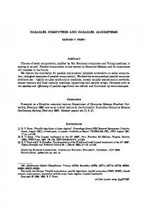
The Communication Cycle: To understand more about how communication occurs on a cycle basis, one needs to understand the actions taken during a cycle. At every synchronization cycle the CC reads transmission and reception grants from the VME register mailboxes that the GCI set up in the last cycle and sets up the communications accordingly. It then reads the requests that
PPs
have posted
and
forwards
one of them
to the GCI.
Only
one request
is forwarded
per
cycle. The CC and GCI then reach a synchronization point and the CC is through with its preliminary work. The GCI control receives the connection requests from the cluster controllers during this cycle and arbitrates connection for the next cycle. The GCI then writes the VME register
mailboxes
with grant
not be serviced are queued shown in Figure 3. Four
signals
Transmission include the start circuitry resulting
are
(EOT)
a signal
used
by the GCI.
in defining
signal.
to switch
information
All other the
crossbar
for the next The actions
a cycle. signals (SW)
taken
The and
Any remaining
requests
by the CC and GCI during
baseline
are defined
signal
in relation
signals
for the
for a cycle
End-Of-
Other
of reception
could
a cycle are
is the
to this signal. start
that
signals
(RX)
and
of transmission (TX). Overhead is added by the synchronization time for the TX/RX for the optical links. The optical links we use have a rather large synchronization time in a total overhead (latency) per cycle of 60 microseconds. With 64 kilobyte data
packets, the effective data rate works out to about of 4.1 milliseconds. This represents a 71 percent megabyte/sec. The 4.1 millisecond are most
cycle.
busy.
The
cycle time is necessary exchange
example
in the
15.98 megabyte/sec per link with a cycle time efficiency of the peak data transfer rate of 20
for those next
times that
chapter
the communication
is one of those
times.
resources In this case,
Overh_ S_ter_ Commumcation for communication fault Read PP communication request Allocate other resources Write request and status to GCI Release halo to GCI
o
o
GCI waits for iafo from CC Read requests Check for communication faults Arbitrate links Write grants and status for next cycle Load crossbar
m
7. ?, Time
Figure
during
any
than
one
cycle,
2 processors resulting
controller
allowed
transfer
64
complete if the
the
DMA
DMA
was
from
the
a send
to the
resources to
3: A Breakdown
DP
this
set
the
shared
cycle
time.
tests
to do
plus
the
show
that
priority
over
occurring
memory
60
the
shared
and
a receive timing
EOT
RX TX
on
a cycle
is shown
Arbitration:
mined and
by the
PP1
ing send CC-PP basis gets
had
CC
Priority
on a round
the
next
requests.
Requests
are
placed
arbitration
scheme.
The
provided arbitrated
a send
no
request,
Proteus
basis.
conflicts
on the
next
exist. cycle.
GCI
could
some
a small
amount
the
by
more
for the
in the
take
be dropped
in Figure
made
contention
error
it should
accesses
that
being
DP
3.125
DP
memory
milliseconds
of overhead
to 3.325
to
milliseconds
to the
DP.
In these
tests
the
were
not
accessing
the
DP
PEs
4.
EOT
urges
Communication
among
robin
are
a design
plus
time
memory
3325-4100
Request
causes
that correctly,
cycle
Cycle
accesses
This
microseconds
the
Cycle
4: The
and
bus.
If designed
bus.
Figure
Communication
It is suspected
a send
memory
Proteus
are
to occur.
of data
Sample
complete
up
a receive
contention
kilobytes
shared
on
in a longer
cycle. had
and
of the
the
PPs
for forwarding
For instance
cycle
would
into arbitrates
If a conflict
the
if the
have queue from
exists
Cycle
requests
priority
priorities
for a given
was
(PP2,
on a round a request
Timing
PP3,
robin
pool request,
to the (PP1, PP4,
approach
GCI
PP2,
is deterPP3,
PP1)
PP4)
for post-
similar
to the
on a first-request/first-serve it stays
in the
queue
and
Optimal Dual Port Performance: The methodof involving the DP in the inter-cluster communicationscan impact efficiencyin termsof sharedmemoryaccess.This sharedmemory accesscan result in contentionfor the sharedmemorybustherebydegradingperformance.The following codefragmentsshowhow to optimizeDP accessto minimizetotal memoryaccesses. "A", "B", and "C" arearraysof elementswith sizeequalto the data packetandresidein shared memory."DP" is the DP packetresidingin DP memory.All operationsoccurfor all elementsin the arrays. Notethat in the efficientcaseno unnecessary data movements are performed. Efficient
DP Use
For
Receive
A=B+DP
{h