Apr 16, 1992 - An example of converting a simple IF-THEN-ELSE statement to an ADD. : : 11. 8. An example of merging consecutive ADDs, where ADD1 is ...
.
Minimizing Syntactic Variance with Assignment Decision Diagrams Viraphol Chaiyakul Daniel D. Gajski Loganath Ramachandran Technical Report #92-34 April 16, 1992
Dept. of Information and Computer Science University of California, Irvine Irvine, CA 92717 (714) 856-8059
Abstract Most synthesis systems generate designs from hardware descriptions by relating each language construct to a particular hardware structure. Thus, designs obtained from these systems are dependent on description styles. In other words, semantically equivalent descriptions with di�erent ordering or grouping of conditional and assignment statements, could generate designs with distinctively di�erent cost and performance. This paper introduces a new representation that minimizes the syntactic variance of di�erent description styles. We also propose an algorithm for conversion of hardware descriptions into this new representation. In addition, using this representation for scheduling results in a drastic reduction on the number of control steps required to synthesize the description. Experimental data on several examples show e�ectiveness of the proposed approach.
Contents 1 Introduction
3
2 Overview of our approach
5
3 Assignment Decision Diagrams
7
4 Converting input description into ADD
9
4.1 4.2 4.3 4.4 4.5
Converting an assignment statement : : : Converting an IF-THEN-ELSE statement Converting a CASE statement to ADD : : Converting a loop to ADD : : : : : : : : : Merging of two consecutive ADDs : : : :
: : : : : : : : : : : : : : : : : : : : : : : : : : : : : : : : : : : : : : : : : : : : : : : : : : : : : : : : : : : : : : : : : : : : : : : : : : : : : : : : : : : : : : : : : : : : : : : : : : : : : : : : :
10 10 11 11 12
5 Experimental results
14
6 Conclusion
17
7 References
17
1
List of Figures 1
Examples of descriptions that have the same semantics but di�erent styles: (a) di�erent ordering of conditional branches, and (b) di�erent grouping of conditional branches. : : : : : : : : : : : : : : : : : : : : : : : : : : : : : : : : : : : 2 Two descriptions with the same semantics but di�erent ordering of statements: (a) description 1 and its corresponding control- ow graph, and (b) description 2 and its corresponding control- ow graph. : : : : : : : : : : : : : : : : : : : : 3 Overview of the proposed approach: (a) a general high-level synthesis system, (b) incorporating the proposed approach. : : : : : : : : : : : : : : : : : : : : : 4 The Assignment Decision Diagram. : : : : : : : : : : : : : : : : : : : : : : : : 5 Algorithm for converting a list of statements to an ADD . : : : : : : : : : : : : 6 Examples of ADDs for assignment statements. : : : : : : : : : : : : : : : : : : 7 An example of converting a simple IF-THEN-ELSE statement to an ADD. : : 8 An example of merging consecutive ADDs, where ADD1 is taken from Figure 7 and ADD2 is taken from Figure 6. : : : : : : : : : : : : : : : : : : : : : : : : : 9 Usages of language constructs in each example. : : : : : : : : : : : : : : : : : 10 Results from the experiment using traditional approach and our approach. : :
2
3 4 5 7 9 10 11 12 15 16
1 Introduction High-level synthesis is a process of synthesizing design from a given abstract behavioral description. In general, the process includes: compiling descriptions into an internal representation, transforming the internal representation into a more suitable form for synthesis, partitioning operations into control steps, and binding operations and interconnects to the appropriate resources. Input descriptions to the synthesis system usually contain a set of high-level languageconstructs, (e.g., conditional branches, loops) that make use of complex data types, (e.g., integers, arrays, and records). Most systems synthesize designs from such descriptions by associating each language construct with a particular hardware structure. For example, conditional branches and loops are translated to control structures [5, 7, 9, 14], while operations in basic blocks are executed in a datapath [7, 12]. Because of the
close relationship between language constructs and the synthesis algorithms the design quality obtained from these systems is dependent on the input description. In other words, semantically equivalent descriptions that di�er syntac-
tically could result in distinctively di�erent designs. Let us consider systems, which evaluate conditions of a branch statement in the control step that precedes operations in the branches [5, 7, 9, 14, 18]. Results generated by these systems depend on the way conditional branches are ordered or grouped in the input description. For example, Figure 1(a) shows two descriptions that have the same semantics but di�erent ordering of conditional branches. When scheduling Description1 and Description2 with hardware
Description 1
ST1 ST2
d := c + e;
ST1
if (a < 2) then
if ((b + c) < 2) then
ST2
if ((b + c) < 2) then
if (a < 2) then
X := Y + Z; ST3
Description 3
Description 2
d := c + e;
ST1 ST2
ST3 ST3
X := Y + Z;
end if;
end if;
end if;
Description 4
d := c + e;
d := c + e;
if (a =1) OR (b =2) then
if (a = 1) then X := Y + Z;
X := Y + Z; end if;
end if; if (b = 2) then
ST4
X := Y + Z;
end if;
ST1 ST2 ST3 ST4
end if; Denotes a state boundary
(a)
introduced by the scheduler.
(b)
Figure 1: Examples of descriptions that have the same semantics but di�erent styles: (a) di�erent ordering of conditional branches, and (b) di�erent grouping of conditional branches. constraints of one adder and one comparator, we nd that Description1 requires three states in comparison to the four states required by Description2 (Figure 1(a)). This additional state is inevitable since expressions (c + e) and (b + c) cannot be executed in the same state when only a single adder is available. Figure 1(b) shows two descriptions with di�erent grouping of conditional branches. Scheduling these two descriptions us3
ing similar hardware constraints (one adder and one comparator) produces designs with three states for Description3, and four states for Description4, as shown in Figure 1(b). Description4 requires an additional state because the value of variable X is computed twice. Some algorithms, such as the Path-based Scheduling [4], try to minimize the impact of nested conditions by considering all possible paths in the description. In these algorithms, operations are scheduled according to the dependency in the Control-Flow Graph (CFG), where nodes represent assignment or conditional statements and edges represent the ordering of execution for each node. Although the impact of nested conditions is minimized by path-based scheduling, statement ordering is still crucial. This fact is illustrated in Figure 2, which shows two semantically identical descriptions with di�erent ordering of operations. Performing path-based scheduling with constraints of
1 a := b + c; j := k * l; if (X) then d := e + f; end if; m := n * o;
−−1 −−2 −−3 −−4 −−5 −−6
2
1
ST1
3 X 4
6
−−1 −−2 −−3 −−4 −−5 −−6
X
5
(a)
a := b + c; if (X) then d := e + f; end if; j := k * l; m := n * o;
ST1
2 X 3
X
4
5
Denotes a state boundary introduced by the scheduler.
ST2
(b)
6
ST2 ST3
Figure 2: Two descriptions with the same semantics but di�erent ordering of statements: (a) description 1 and its corresponding control- ow graph, and (b) description 2 and its corresponding control- ow graph. an adder and a multiplier, would produce a design with two states for the description in Figure 2(a), and three states for the description in Figure 2(b). Thus, results obtained with the path-based scheduling algorithm depend on the ordering of operations in the description, as mentioned in [4]. The syntactic variation in the description can be minimized by applying a few transformations on the input description. Although many synthesis systems use transformations [1, 17] on their internal representation, these transformations do not try to reduce the impact of syntactic di�erences in the input descriptions on the synthesized design. They are mainly intended for the purpose of optimizing the nal design [16]. For example, none of the descriptions from Figure 1(a),(b), or Figure 2(a),(b) would be in uenced by published transformation techniques. A simple solution to avoid the ine�ciences caused by syntactic di�erences is to force the designer to write descriptions that ts the algorithm used inside the synthesis sys4
tem. This solution is impractical because the designers would need to acquire detailed knowledge of the synthesis algorithms that are used. In order to increase the acceptability of synthesis, consistent results must be generated regardless of syntactic variation, i.e., descriptions with the same semantics should produce identical designs in spite of grouping and ordering of language constructs. This paper proposes a new approach to resolve problems with syntactic di�erences in the description. The next section of this paper contains the overview of our approach. A new internal representation, called ADD, is introduced in section 3, and detailed algorithms for constructing this representation are described in section 4. In section 5, we present results from our experiments on ve examples to illustrate the e�ectiveness of the proposed approach. Finally, we present our conclusions, based on our experiments.
2 Overview of our approach The rst task in high-level synthesis is to compile the input description into an internal representation, as illustrated in Figure 3(a). Typical examples of such internal representations include, the Control-Data-Flow Graph(CDFG)[6], the Control-Flow Graph(CFG)[6], and the Value Trace(VT)[10, 13]. The compilation is usually accom-
N descriptions with the same semantics but different ordering and/or grouping of operations and/or conditional branches
M different implementations with the same architecture and resources constraints
Description 1
Hardware 1
Description 2
Hardware 2
High−level synthesis system Compilation
: M
:
Transformation
: M
Scheduling
M
Binding
Description N
Hardware M CDFG/CFG/VT * M is less than or equal to N (a)
Description 1
Description 2
Traditional high−level synthesis system
Proposed conversion procedures
Transformation
Scheduling 1
Description N
Hardware i Binding
1
Assignment Decision Diagrams (b)
Figure 3: Overview of the proposed approach: (a) a general high-level synthesis system, (b) incorporating the proposed approach. plished by a one-to-one mapping of the input description into the internal representation. 5
In other words, each language construct in the description is realized with a particular topology of nodes in the representation. For example, a VHDL[15] description can be compiled into a CDFG by mapping computations in a basic block to nodes in a data ow graph, and a conditional construct to a control node [9, 11]. Similar one-to-one mappings from VHDL to CFG and from ISPS [2] to VT can be found in [4, 10, 13]. Due to the one-to-one correspondence that exist between the constructs of the input descriptions and the schema for the internal representation, these compilers produce di�erent representations for di�erent descriptions. The internal representations of two given descriptions could be far di�erent even if the descriptions are semantically equivalent. If these representations are used by algorithms in subsequent synthesis tasks, di�erent hardware would result (Figure 3(a)). This led us to believe that the dependency of the synthesis system on input description can be resolved by modifying the compilation scheme and improving the internal representation. Thus, we introduce a new uniform representation called the Assignment Decision Diagrams(ADD) and propose an algorithm for conversion of input descriptions into this representation. The main objective of the ADD representation and the conversion algorithms is to resolve the discrepancies in the description that are caused by the ordering and grouping of conditional branches and/or operations. The proposed algorithms can replace or be incorporated with the compilation task, as shown in Figure 3(b). Further transformations that optimize the design, and other synthesis tasks can then be applied to the resultant ADD. The proposed representation, ADD, is capable of recognizing conditions and computations in a data- ow fashion. Hence, conditional branches and computations are ordered only by data dependencies and not by positions in the description. This representation is similar to the Binary Decision Diagram (BDD) [3, 8], which is used in logic veri cation and synthesis. The conversion algorithm is designed to produce a ADD that represents the most parallel implementation (i.e., the implementation that requires the least number of states). Thus, the resultant representation is free from implicit state boundaries that might inadvertently get introduced due to some speci c language constructs. Furthermore, di�erent grouping of conditional branches are resolved by attening conditions on the assignment path1 basis. Thus, the representation will not be a�ected by the grouping of conditional constructs in the description. ADD is discussed in more detail in section 3 and the conversion algorithm is presented in section 4. An assignment path is a path generated by conditional branches from the beginning of a description to the referenced assignment statement. 1
6
3 Assignment Decision Diagrams The function of a digital system can be viewed as a set of computations on the inputport values and contents of the internal storage elements in the system. The results of the computation are stored in internal storage elements, or assigned to an output port. Hence, a digital system can be represented as a set of conditional assignments to targets that represent storage units or output ports in the form of Assignment Decision Diagram(ADD). Figure 4 shows a general representation of a digital system in ADD.
Legend :
Assignment values
Assignment decision
Assignment conditions
Assignment target
=
* +
= Read node (storage unit/input)
= Data flow graph
= Write node (storage unit/output) value1 value n condition 1 condition n
= Assignment decision node
−
= Operator node
Figure 4: The Assignment Decision Diagram. The ADD representation consists of four parts: (1) the assignment value, (2) the assignment condition, (3) the assignment decision, and (4) the assignment target, as shown in Figure 4. These parts are implemented with four types of nodes: operation nodes, read nodes, write nodes and assignment decision nodes (ADN). The assignment value part consists of read nodes and operation nodes. This part represents the computation of values that are to be assigned to a storage unit or an output port. The value is computed from current contents of storage units, inputs ports, or constants. These are represented by read nodes. The actual computation is represented as a data- ow graph that contains operator nodes, which correspond to the type of operations that are performed. The assignment condition part consists of read nodes and operation nodes that are connected as a data- ow graph to represent computation of a condition. The end product 7
of the condition-computation is a binary value that evaluates to true or false. This true/false value is used as a guarding condition for the assignment value. The assignment-decision part consists of a Assignment Decision Node (ADN). The ADN selects a value from a set of values that are provided to it. These input values are computed by the assignment-value part of the ADD. The selection is based on the conditions computed by the assignment condition part of the ADD. If one of the conditions to the ADN evaluates to true then the corresponding input value is selected. It is also possible that none of the conditions of a ADN evaluate to true at a given time. In this case none of the input values are selected. The assignment-target is represented by a write node. The write node is provided with the selected value from the corresponding ADN. A value will be assigned to the write node, only if one the conditions to the corresponding ADN is true. And since only one value can be assigned to a target at any given time, all assignment conditions for each target are mutually exclusive. The unique feature of ADD is its capability to represent conditions and computations in a consistent data- ow fashion. Thus, operations in ADD are ordered by their data dependency only. In other words, ADD is free of control dependency that are introduced in the description. With this capability, ADD can represent the most parallel implementation for a given description. In addition to representing the most parallel representation, ADD can be used to represent multi-state designs. Such multi-state designs become necessary if the description contains a loop construct with variable bounds. In this case, the corresponding ADD would contain a special storage unit called State reg that represents the control step-sequencer. This State reg has the same representation as any other storage units. Assignments to State reg represent the sequencing of control steps, where each assignment value is a constant that represents a control step, and each assignment condition represents the sequencing between the steps. ADD can also be used to represent storage elements with multiple ports. Storage units that contain multiple read ports are represented in ADD as a read node with multiple output lines, where each line represents a read port. On the other hand, storage units with multiple write ports are represented with multiple ADNs, where each ADN represents assignments through a write port. A value is written through a port only if its corresponding assignment condition evaluates to true. Since a storage unit with multiple read and/or write ports primarily is implemented as a two dimensional storage unit, (such as register les or memories), an index is assigned to each of these ports. This index indicates the location where the value is to be read from or written to. ADD can be implemented as an undirected acyclic graph, where each read, write, operation or assignment decision node is implemented as a node with di�erent attributes, and connections are implemented as undirected edges. Representing a description would 8
require, in the worst case, a graph whose size is proportional to the number of conditional assignments to all the ports and storage units.
4 Converting input description into ADD Given an input description, constructing the equivalent ADD is a constructive process. The algorithm (Figure 5) starts from the first statement of the description with the variable ADDdesc set to null. Then, at each iteration, a statement, ST , is taken from the description and converted into its corresponding ADD called ADDST . Subsequently, ADDST is merged into the ADDdesc . This process is repeated until the last statement is reached. conv stmts to ADD ( rst statement,last statement) returns ADD ; ADDdesc = �; ST = rst statement; while (ST = last statement) case (type of statement(ST)) assignment statement: ADDST = conv asstmt(ST); ST = statement following ST; if statement: ADDST = conv if(ST); ST = statement following the \end if"; case statement: ADDST = conv case(ST); ST = statement following the \end case"; loop statement: ADDST = conv loop(ST); ST = statement following the \end loop"; end case; ADDdesc = merge consecutive ADDs(ADDdesc , ADDST ); end while; return ADDdesc ;
Algorithm:
6
Figure 5: Algorithm for converting a list of statements to an ADD . The conversion of a statement is carried out by an algorithm which is designed to handle a particular language construct; for example, conv asstmt is used for converting an assignment statement, conv if is used for converting an IF-THEN-ELSE statement, etc. Discussion of these algorithms are provided in following sections.
9
4.1 Converting an assignment statement An assignment statement consists of two parts, the computation and the target variable/signal. The computation is represented in ADD as a data- ow graph with operands as read nodes and operators as operation nodes. The target variable/signal is represented as the assignment target. The result of the computation from the data- ow graph is assigned to the assignment target with a true assignment condition. Figure 6 shows examples of ADDs for assignment statements (A := X ? B ;) and (RF [J ] := C � E ;).
TRUE
X
J
B
TRUE
−
Result from conv_asstmt(A:=X−B);
A
C
E *
Result from conv_asstmt(RF[J]:=C*E);
RF
Figure 6: Examples of ADDs for assignment statements.
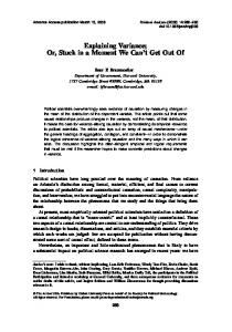
4.2 Converting an IF-THEN-ELSE statement Consider a general IF-THEN-ELSE statement below: IF (cond) THEN STB1 ELSE STB2 where STB1 and STB2 are blocks of statements. The IF-THEN-ELSE statement is converted into its maximal parallel representation by rst converting the statement blocks STB 1 and STB 2 to their ADDs, ADDthen and ADDelse , respectively. This is accomplished by invoking the algorithm conv stmts into ADD with the list of statements in STB 1 and STB 2. Hence, if STB 1 or STB 2 contains nested conditional branches, the innermost conditions are converted rst, and the outermost conditions are converted last. cond is used as the guarding condition for all assignments in ADDthen . On the other hand, assignments in ADDelse are guarded by the condition cond. Finally, ADDthen and ADDelse are merged by simply combining all elements from both ADDs without having to resolve any data dependency, since assignments in both ADDs are mutually exclusive. This mutual exclusion is guaranteed because of the truth value of conditions (cond) and (cond). Figure 7 shows an example of converting a simple IF-THEN-ELSE statement.
10
Step 1: Result from conv_asstmt(X:=Y+Z); and conv_asstmt(RF[I]:=C+D); if (b = 2) then X := Y + Z; RF[I] := C + D; else X := Y − Z; end if;
TRUE
Y
Z +
C
D
Step 2: Result from conv_asstmt(X:=Y−Z); I
TRUE
+
Z
Y −
Step 3: Result from conv_if(if (b=2) then ... end if;); I
C
D +
b
2 =
Y
Z
−
+
not
Input description X
RF
x
RF
X
Figure 7: An example of converting a simple IF-THEN-ELSE statement to an ADD.
4.3 Converting a CASE statement to ADD CASE statements are handled very similarly to the IF-THEN-ELSE statement. Given a CASE statement each branch is converted into its ADD. Then, the condition for each branch is used as the guarding condition for all assignments in its corresponding ADD. Finally, the resultant ADDs for all branches are merged.
4.4 Converting a loop to ADD Consider a general loop construct below: STB1 WHILE (cond) LOOP STB2 END LOOP; STB3 where STB1, STB2 and STB3 are blocks of statements. The iteration of the loop has to be done in a sequential manner. Thus, the most parallel implementation for a loop would require at least three control steps, namely, ST 1, ST 2 and ST 3. The loop is converted to ADD by rst updating assignment to State reg, based on the following criteria: ST 2 is assigned to State reg if its current value is ST 1 and cond is true, or if its current value is ST 2 and cond is true; ST 3 is assigned to State reg if its current value is ST 1 and cond is false, or its current value is ST 2 and cond is false. Then, statements in STB1, STB2 and STB3 are independently converted to ADDs and the results are merged.
11
4.5 Merging of two consecutive ADDs The conversion process into ADDs aims to produce the maximal parallel implementation. Thus, merging of two consecutive ADDs(Figure 5), requires analysis of data dependency between the two ADDs such that assignment in the resultant ADD can be performed in parallel without changing the semantics. Consider the merging of two consecutive ADDs, ADD1 and ADD2, where ADD1 represents statements which precede statements in ADD2 in the original description. The data dependency-analysis tasks include: 1) read-after-write dependency-analysis, 2) read-after-read dependency-analysis and 3) write-after-write dependency-analysis. In order to obtain the correct merging, the analysis must be applied in the order given above. Also, it should be noted that there is no dependency between variables that are written after they were read. This is because, in ADD, assigned values will only be used in the next state. Figure 8 shows the merging of two consecutive ADDs.
I
C
D
b
+
2
Y
=
Z
X
−
+
B
TRUE
C
E
−
*
A
RF
J
not RF
X
ADD 1
ADD 2 MERGE
b
2 =
Y
Z +
B
I
J
C
−
not
D
E
TRUE
=
−
−
not
+
*
and X
A
RF
ADD result of merging consecutive ADDs
Figure 8: An example of merging consecutive ADDs, where ADD1 is taken from Figure 7 and ADD2 is taken from Figure 6. To resolve a read-after-write dependency, values for a storage unit in ADD1 are substituted for each of its read instances in ADD2 . Consider a variable Si that needs to be resolved. If in ADD1 , Si contains n : (n > 1) assigned values (A0 . . . An) which are guarded by n assignment conditions (C0 . . . Cn ), then the substitution requires that 12
each value (Ai) will be substituted according to its assignment condition (Ci). This is accomplished with the following steps: 1) Duplicate each usage path 2 of Si in ADD2 into (n + 1) paths. 2) For each j of the rst n duplicated paths, 2.1) substitute the read node of Si with a distinct assigned value from ADD1, Aj . 2.2) substitute the condition of that duplicated path 3, C(j)dup, with (Cj ^ C(j)dup), where Cj is the assignment condition for Aj . 3) If it is possible that none of assignment conditions, (C0 . . . Cn), can evaluate to true, no value will be assigned to Si in ADD1 . In this case, the value of Si that is read from ADD2 will be the current content of Si from ADD1. We resolve this by rst creating a condition, Cx, that is mutually exclusive to all assignment conditions of Si in ADD1 (i.e., Cx = C0 ^ C1 ^ . . . ^ Cn). Then, the condition of the (n + 1)th duplicated path, C(n+1)dup , is substituted with (Cxclusive ^ C(n+1)dup). The read-after-write dependency of a two-dimensional storage unit can be resolved by applying similar steps as above. Values assigned to each write port of that unit in ADD1 are substituted for every read port in ADD2 . Figure 8 shows an example of resolving read-after-write for the storage unit X . It should be noted that by duplicating the usage paths of Si and substituting assigned values of Si according to its assignment conditions, we are actually attening the grouping of conditions that are speci ed in the description. A read-after-read dependency of a storage unit or an input port is resolved by creating a common read node for this unit in the resultant ADD. This is to ensure that values are read from the same source. In the case of a two-dimensional storage unit, values that are read depend on their corresponding indices. Moreover, values that have the same index can share the same port. Thus, resolving read-after-read dependency of a two-dimensional storage unit requires merging of read ports that have the same index. Figure 8 shows an example of resolving read-after-read dependency for the storage unit C. A write-after-write dependency of a storage unit, Si, is resolved such that the resultant assignment conditions for Si will guarantee only one value can be assigned to Si at any given time. Since ADD2 represents statements that are executed after ADD1, values for Si from ADD1 will be assigned only if assignment conditions for Si in ADD2 are all false. In other words, if there is always one assignment condition for Si in ADD2 that evaluates to true, then assignment values for Si in ADD1 will be disregarded. This is accomplished with the following steps: Usage paths of a node is a set of paths from that node to immediate assignment decision nodes. For example, usage paths of read-node X in ADD2 of Figure 8 is (X ! (?)). 3 Conditions of a usage path are assignment conditions to which the usage path is associated with. For example, conditions of a usage path (X ! (?)) in ADD2 of Figure 8 is (TRUE ). 2
13
1) Create a common write node, Scommon , for Si. 2) Move the assignment decision node for Si in ADD2 to Scommon . 3) Create a mutually exclusive condition, Cx, from assignment conditions of Si in ADD2 (i.e., Cx = C0 ^ C1 ^ . . . ^ Cn). 4) if Cx 6= FALSE then for all Ai, which is an assigned value of Si in ADD1 , assign Ai to Scommon with the assignment condition of (Ci ^ Cx), where Ci is the corresponding assignment condition for Ai in ADD1. Write-after-write dependency of a two-dimensional storage unit can be resolved by applying similar steps to all the write ports. Figure 8 shows an example of resolving write-after-write dependency for the two-dimensional storage unit, RF .
5 Experimental results We have tested our approach on ve examples, namely: � a clock division circuit, which divides the input clock frequency, fin, such that the output frequency, fout = (N=M )fin , where N and M are given as inputs to the circuit, � a timer, which contains two counters that keep tally of the clock pulse, � Kim's example which is taken from [7], � the AM2901, which is a four-bit microprocessor slice from Advanced Micro Devices, and � the AM2910, which is a twelve-bit microprogram controller from Advanced Micro Devices. The clock division circuit, AM2901 and AM2910 are benchmarks from the 1992 Workshop on High-level Synthesis [19]. The behavior of each example is written in VHDL using process-level constructs, such as variable, array, if-then-else, and case statements. For each example, we created three di�erent descriptions (A, B , and C ) that have the same semantics but di�er in the ordering and grouping of statements and/or conditions. Figure 9 shows the usages of di�erent language constructs in each of the descriptions. Hardware is synthesized from these descriptions using two di�erent approaches: traditional approach and our approach. In the traditional approach, the VHDL description is converted into a CDFG. Then, basic blocks in the CDFG are independently scheduled using Force-Directed List-Scheduling(FDLS) algorithm [12]. The overall schedule is constructed by assuming that conditions for each conditional branch are scheduled in a state prior to the operations in the branches. Thus, states in di�erent branches are mutually exclusive and are scheduled to share the same hardware using the algorithm given in Bridge [14]. In our approach, the VHDL description is converted into ADD using algorithms described in Section 4. Then, the ADD is scheduled using the FDLS algorithm with merging of operations that reside on mutually exclusive paths. 14
Various usages of language constructs in the description Examples
* Clock division circuit
Timer circuit
Kim’s example
* AM2901
* AM2910
# of # of assignment conditional statements branches
max. level of nested conditional branches
# of one−dimensional variables
# of two−dimensional variables
Description A
11
6
2
5
0
Description B
12
7
3
5
0
Description C
12
8
3
5
0
Description A
21
7
5
9
0
Description B
23
6
5
11
0
Description C
21
12
10
9
0
Description A
24
2
2
8
0
Description B
23
3
1
8
0
Description C
24
2
2
8
0
Description A
102
7
1
10
1
Description B
103
13
1
10
1
Description C
101
17
1
10
1
Description A
129
42
3
5
1
Description B
131
38
3
6
1
Description C
131
38
4
9
1
* Benchmarks from the International Workshop on High−Level Synthesis.
Figure 9: Usages of language constructs in each example.
15
To observe the e�ect of di�erences in the description on the synthesized designs, we use the same resource constraints to schedule the three di�erent descriptions of each example. The results of the experiments are shown in Figure 10 where numbers in the resources columns represent resource constraints for the scheduling. The numbers in states columns represent the total number of states in the resultant design, the number of states in the longest execution path, and the number of states in the shortest execution path. The proposed algorithms are implemented in C on a SPARC workstation. The time taken for the conversion of input descriptions into ADD is given in Figure 10.
Traditional approach
resources
states (tot/long/short)
time taken to convert to ADD (sec.)
resources
states (tot/long/short)
Description A
1 add
12/12/7
10
1 add
1/1/1
Description B
1 add
12/12/7
15
1 add
1/1/1
Description C
1 add
14/14/7
12
1 add
1/1/1
Description A
1 dec
8/8/3
15
1 dec
2/2/1
Description B
1 dec
11/11/3
12
1 dec
2/2/1
Description C
1 dec
16/16/3
40
1 dec
2/2/1
Description A
2 add, 1 sub, 2 comp
6/6/6
7
2 add, 1 sub, 2 comp
6/6/5
Description B
2 add, 1 sub, 2 comp
12/12/4
7
2 add, 1 sub, 2 comp
6/6/5
Description C
2 add, 1 sub, 2 comp
7/7/6
12
2 add, 1 sub, 2 comp
6/6/5
Description A
1 add, 1 inc, 1 RF
10/10/10
63
1 add, 1 inc, 1 RF
1/1/1
Description B
1 add, 1 inc, 1 RF
24/17/10
102
1 add, 1 inc, 1 RF
1/1/1
Description C
1 add, 1 inc, 1 RF
34/23/12
162
1 add, 1 inc, 1 RF
1/1/1
Description A
1 inc, 1 dec, 1 RF
11/11/6
304
2 inc, 2 dec,
1/1/1
Description B
1 inc, 1 dec, 1 RF
9/9/6
278
2 inc, 2 dec,
1/1/1
Description C
1 inc, 1 dec, 1 RF
10/10/6
310
2 inc, 2 dec,
1/1/1
Examples
Clock division circuit
Timer circuit
Kim’s example
AM2901
AM2910
Our approach
add : Adder sub : Subtractor inc : Incrementer dec : Decrementer comp : Comparator
AM2901 RF : 16−word by 4 bit register−file with 2 read and 1 write port AM2910 RF : 9−word by 12−bit register−file with 1 read and 1 write port
Figure 10: Results from the experiment using traditional approach and our approach. 16
Figure 10 show that di�erences in the description styles can a�ect the results of synthesis based on traditional approaches. For example, given the three descriptions of the AM2901 (i.e., DescriptionA, B , and C ) the traditional approach would produce hardware that requires (10/10/10), (24/17/10), and (34/23/12) states, respectively. On the other hand, our approach resulted in (1/1/1) for all three descriptions. Our approach also produces consistent results for the three di�erent descriptions for all other cases. Moreover, experimental results also show that the proposed approach reduces the required number of states in the synthesized hardware. This is because the description is converted into its maximal parallel representation. If the required resources are su�cient, a hardware with one state will be produced (the clock division circuit, AM2901, and AM2910). However, if the resources are not su�cient, the scheduling algorithm will introduce states such that the available resources can be shared e�ciently. Since the conditions for all the branches are attened, the scheduling is independent of implicit state boundary that could be introduced by language constructs. In our experiments two of the examples (the timer circuit and Kim's example) required scheduling.
6 Conclusion In order for a high-level synthesis system to be successfully accepted by the users, it has to be able to produce consistent results even with syntactic variance in the description, such as di�erent ordering or grouping of statements or conditional branches. We showed that these variations can be minimized by using ADD , a representation which is independent of syntactic grouping and ordering. Results from the experiment on ve examples, three of which are benchmarks from [19], show that ADD and the proposed algorithm can e�ectively minimize syntactic variance in the description. Furthermore, results also show that the proposed approach could e�ectively reduce the required number of states in the synthesized design. Future research includes studying of impact of loop restructuring and reordering wait statement dependencies.
7 References [1] A.V. Aho, R. Sethi and J.D. Ullman, Compilers: Principles, Techniques and Tools, Reading, MA: Addison-Wesley, 1986. [2] M.R. Barbacci, G.E. Barnes, R.G. Cattell, and D.P. Siewiorek, \The ISPS Computer Description Language," Technical Report, Department of Computer Science, Carnegie-Mellon University, 1977. 17
[3] R.E. Bryant, \Graph-Based Algorithms for Boolean Function Manipulation," IEEE Trans. CAD, vol.C-15, no.8, pp.677-689, Aug. 1986. [4] R. Camposano, \Path-Based Scheduling for Synthesis," IEEE Trans. CAD, Vol.10, no.1, pp.85-93, Jan. 1991. [5] R. Camposano and W. Rosenstiel, \Synthesizing Circuits from Behavioral Speci cations," IEEE Trans. CAD, vol.8, no.2, pp.171-180, Feb. 1989. [6] R. Camposano and W. Wolf, High-Level VLSI Synthesis, Kluwer Academic Publishers, 1991. [7] T. Kim, J.W.S. Liu, and C.L. Liu, \A Scheduling Algorithm For Conditional Resource Sharing," Proc. ICCAD'91, pp.84-87, 1991. [8] C.Y. Lee, \Representation of switching circuits by binary-decision programs," Bell. Syst. Tech. J., vol.38, pp.985-999, Jul 1959. [9] J.S. Lis and D.D. Gajski, \Synthesis from VHDL," Proc. IEEE Int. Conf. on Computer Design'88, pp.378-381, 1988. [10] M.C. McFarland, \The Value Trace: A Data Base for Automated Digital Design," PhD. Dissertation, Department of Electrical Engineering, Carnegie-Mellon University, 1978. [11] A. Orailoglu and D.D. Gajski, \Flow Graph Representation," Proc. 23rd DAC., pp.503-509, 1986. [12] P.G. Paulin and J.P. Knight, \Force-Directed Scheduling for the Behavioral Synthesis of ASIC's," IEEE Trans. CAD, vol.8, no.6, pp.661-679, Jun. 1989. [13] E.A. Snow, \Automation of Module Set Independent Register-Transfer Level Design," PhD. Dissertation, Department of Electrical Engineering, Carnegie-Mellon University, 1978. [14] C.-J. Tseng, R.W. Wei, S.G. Rothweiler, M. Tong and A.K. Bose, \Bridge: A Versatile Behavioral Synthesis System," Proc. 25th DAC., pp.415-420, 1988. [15] Standard VHDL Language Reference Manual. New York: The Institute of Electrical and Electronics Engineers, Mar. 1988. [16] R.A. Walker and R. Camposano, A Survey of High-Level Synthesis Systems, Kluwer Academic Publishers, 1991. [17] R.A. Walker and D.E. Thomas, \Behavioral Transformations for Algorithmic Level IC Design," IEEE Trans. CAD, vol.8, no.10, pp.1115-1128, Oct. 1989. 18
[18] K. Wakabayashi and T. Yoshimura, \A Resource Sharing Control Synthesis Method for Conditional Branches," Proc. ICCAD'89, pp. 62-65, 1989. [19] Benchmarks for the Sixth International Workshop on High-Level Synthesis, 1992.
19