Minimum Backup Configuration-Creation. Method for IP Fast Reroute. Shohei Kamamura, Takashi Miyamura, Cristel Pelsser, Ichiro Inoue, and Kohei Shiomoto.
Minimum Backup Configuration-Creation Method for IP Fast Reroute Shohei Kamamura, Takashi Miyamura, Cristel Pelsser, Ichiro Inoue, and Kohei Shiomoto NTT Network Service Systems Laboratories, NTT Corporation 9-11, Midori-Cho 3-Chome Musashino-Shi, Tokyo 180-8585 Japan. Email:{kamamura.shohei, miyamura.takashi, pelsser.cristel, inoue.ichiro, shiomoto.kohei}@lab.ntt.co.jp
Abstract—IP Fast Reroute techniques have been proposed for achieving fast failure recovery in just a few milliseconds. The basic idea of IP Fast Reroute is to reduce recovery time after failure by precomputing backup routes. A multiple routing configurations (MRC) algorithm has been proposed for obtaining IP Fast Reroute. MRC prepares backup configurations, which are used for finding a detour route after failure. On the other hand, requiring too many backup configurations consumes more network resources. It is necessary to recover more traffic flows with fewer backup configurations to ensure scalability. We propose a new backup configuration-creation algorithm for maximizing traffic flows which are fast recovered as much as possible under a limited number of backup configurations. The basic idea is to construct a spanning tree excluding failure links with higher link-loads in each backup configuration. We show that our algorithm has more robust on actual large IP networks. Index Terms—Backup Configuration, IP Fast Reroute, MRC, robustness, scalability
I. INTRODUCTION Link-state routing protocols, such as Open Shortest Path First (OSPF) [1], have been widely used for intra-domain routing resolution, but a few seconds are required to find alternate routes after a failure occurs [2]. This recovery time is too long to achieve robustness for an increasing number of multimedia applications. IP Fast Reroute techniques have been studied for fast failure recovery in just a few milliseconds [2-11]. The basic idea of IP Fast Reroute is to reduce recovery time after failure by precomputing the backup routes. The multiple routing configurations (MRC) method has been proposed for IP Fast Rerouting [2]. The MRC method prepares backup configurations, which are precomputed and used for finding a detour route after a failure. In a backup configuration, some links are assigned a higher metric value. Such links are called isolated links. These isolated links can be regarded as protected links. They are not used to forward the traffic when a resource fails. An arbitrary link is an isolated link in at least one backup configuration. Therefore, we can achieve fast recovery against any single failure using backup configurations. We define the minimum backup configuration-creation problem to maximize the number of traffic flows that are fast
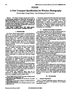
recovered under a limited number of backup configurations. Because the total number of backup configurations is an important factor in terms of scalability, requiring too many backup configurations consumes more network resources. This is because the number of backup configurations is proportional to the size of the forwarding table kept on a router, and link-state messages which are transmitted across the network. It is necessary to recover traffic flows as much as possible with fewer backup configurations to ensure scalability. We propose a new backup configuration-creation algorithm for maximizing the traffic flows that are fast recovered as much as possible under a limited number of backup configurations. The key point of our algorithm is that each backup configuration is made so that the topology, excluding the isolated links, becomes a spanning tree. This process maximizes the number of isolated nodes and isolated links on one configuration. In addition, the links with high link-loads are isolated in priority. The evaluation results show that our algorithm recovers traffic flows with fewer backup configurations than the conventional algorithm [2]. The rest of the paper is organized as follows. In Section II, we discuss the characteristics of backup configurations. We describe IP Fast Rerouting using backup configurations, and then define the problem. In Section III, our new backup configuration-creation algorithm is presented. Our evaluation results are shown in Section IV, and related work is presented in Section V. Finally, we conclude our discussion in Section VI. II. MULTIPLE ROUTING CONFIGURATIONS In this section, we describe the characteristics of backup configurations used with the MRC method and introduce IP Fast Rerouting using backup configurations. We then state our problem. A. Overview of Backup Configurations The characteristics of backup configurations defined by Kvalbein et al. [2] are as follows (Fig. 1). A backup configuration consists of normal links, isolated links, restricted links, and normal and isolated nodes. An isolated link is a link that may fail, and a restricted link is a link that can be used
978-1-4244-4148-8/09/$25.00 ©2009 This full text paper was peer reviewed at the direction of IEEE Communications Society subject matter experts for publication in the IEEE "GLOBECOM" 2009 proceedings.
Topology out I/F
2
isolated node isolated link restricted link
Backup Configuration #3
#2
#1
#a 1 #c #b
#4
6
3
5 4
node 1’s routing table dest
NH
out I/F
dest
NH
out I/F
dest
NH
out I/F
dest
NH
out I/F
dest
NH
out I/F
2
2
#a
2
6
#c
2
2
#a
2
2
#a
2
2
#a
3
3
#b
3
6
#c
3
3
#b
3
3
#b
3
3
#b
4
2
#a
4
6
#c
4
3
#b
4
2
#a
4
3
#b
5
6
#c
5
6
#c
5
3
#b
5
3
#b
5
6
#c
6
6
#c
6
6
#c
6
3
#b
6
6
#c
6
6
#c
for OSPF
for Multiple Routing Configurations (MRC)
dest : destination IP address, NH : Next Hop node, out I/F : output interface
Fig.1. Overview of backup configurations
only as the last hop. The metric of an isolated link is set to the maximum value provided by the link-state routing protocol and the metric of a restricted link is set to a large value, though it is not the maximum value [2]. An isolated node is a node that is only connected to isolated and restricted links. That is, isolated links and nodes are the resources protected by backup configurations. They are not used to forward traffic when a resource fails. Therefore, backup configurations should satisfy the following characteristics. 1) Each backup configuration is a connected graph that does not contain isolated links. 2) The union of isolated nodes and links of all backup configurations correspond to the original topology. 3) Among the links that are connected to an isolated node, at least one is a restricted link, and the others are isolated links. The opposing node of a restricted link must not be an isolated node in the same backup configuration. If backup configurations satisfy the above conditions, an arbitrary link is an isolated link in at least one backup configuration. In addition, if a link failure is caused by an opposing node failure, the links that are connected with the failed node are not used except when the failed node is the destination node. This is because the failed node is the isolated node. This node is only connected to isolated and restricted links. Therefore, the detour route determined by the backup configuration avoids the isolated node. Thus, for each single failure there is a backup configuration that avoids the failed resources. B. IP Fast Reroute using Backup Configurations IP Fast Reroute can be achieved by using backup configurations [2]. Each backup configuration is precomputed and installed in all routers. Backup configurations are used to define different topologies which have separate metrics for each of them. Each router computes the shortest path and then creates the routing entries (relationship between destination IP address
and next hop node) based on the original configuration, and for each backup configuration. If the router detects a link failure, it searches the backup configuration that isolates the link corresponding to the failed link. Next, the identifier of the selected backup configuration is marked in the type of service (ToS) field of the IP header. After marking, the failure-detecting router forwards the packets to the next hop node according to the routing entry of the selected backup configuration. Other routers can forward the IP packets according to the same backup configuration by referring to the ToS field. Psenak et al. and Przygienda et al. are standardizing protocol extensions which can handle IP Fast Rerouting using backup configurations as multi topology routing [12, 13]. C. Problem Statement The total number of backup configurations is an important factor in terms of scalability. This is because the number of backup configurations is proportional to the size of the forwarding table kept on a router, and link-state messages which are transmitted across the network. Figure 1 illustrates an example. While the forwarding table with OSPF is only based on the original topology, this table with MRC is based on the original topology and all backup configurations. Because the number of backup configurations depends on the size of networks [11], it is necessary to recover traffic flows as much as possible with fewer backup configurations to ensure scalability. Therefore, the problem we want to solve is to maximize the number of traffic flows that are fast recovered under a limited number of backup configurations. The requirements for solving the above problem are as follows. First, the number of backup configurations should be minimized. Second, the priority should be attached to failures that are fast recovered for a limited number of configuration environments. III. MINIMUM BACKUP CONFIGURATION CREATION In this section, we present an overview of our algorithm, and
978-1-4244-4148-8/09/$25.00 ©2009 This full text paper was peer reviewed at the direction of IEEE Communications Society subject matter experts for publication in the IEEE "GLOBECOM" 2009 proceedings.
Link cost for creating spanning tree
Restricted link
1
Wr
1 1
2 2
6
leaf 6
2 2
1
3
1
1
1
2
1
5
4
leaf 5
3 leaf
4
2
Isolated link
6
Wr
∞
∞ 3
Wr ∞
4
5
Isolated node
isolated node isolated link restricted link
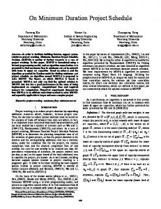
Topology Spanning Tree Backup Configuration Fig. 2 Key idea of our algorithm. Spanning tree is created from topology. Backup configuration is created from spanning tree. The links, which were removed to create the spanning tree, become isolated links. The links, which are connected to the leaf node, become restricted links. The leaf nodes become isolated nodes.
then describe it in detail. A. Overview of Our Algorithm Our strategy is to create backup configurations one by one in turn for generating adaptable backup configurations in an environment where the number of configurations is limited. This approach has two advantages: 1) It is easy to optimize a backup configuration. Optimal backup configuration means the configuration, whose number of isolated nodes and isolated links which appear on it, is maximized. 2) It is easy to purposely isolate a link according to the priority of links. Therefore, even if the available number of backup configurations is limited, we could isolate the links that should be recovered in priority. The key point of our algorithm is that each backup configuration is made so that the topology, excluding the isolated links, becomes a spanning tree (Fig. 2). A spanning tree of a given topology is a minimal set of links that connect all nodes. Therefore, this process maximizes the number of isolated nodes and isolated links on one configuration. In addition, the links with high link loads are isolated in priority. A high link load means that many more traffic flows are in the link. We create a minimum spanning tree by the Kruskal algorithm [15]. A minimum spanning tree is a spanning tree whose summation of the link weights is minimal. Therefore, weights of links with high link loads are set to a higher value because the links with a higher weight tend to be removed at the time of spanning tree creation. B. Algorithm Our algorithm automatically creates backup configurations from an undirected weighted graph, G = (V(G), E(G)) where V(G) corresponds to the set of nodes and E(G) corresponds to the set of undirected links, the maximum number of backup configurations, and link loads. Link loads of all links can be measured from the network. If link loads are unknown, the number of flows accommodated by the links can be used in the same meaning. A flowchart of our algorithm is shown in Fig. 3. In step 1, the weights of all links are decided based on link loads. As previously mentioned, the weight of links with high-link loads is set to a higher value. However, if the weights are uniformly set proportional to the link load, the form of the
spanning tree may become specified. This form may not be appropriate for generating the following spanning tree (step 5). Therefore, our algorithm gives randomness to the weight value according to the normal distribution. A median of normal distribution is determined by the link load. More precisely, the value calculated by the link load of a link divided by the sum of the link load of all links is assumed to be a median. That is, the weight of a link with a high-link load tends to increase, though the randomness remains. It should be noted that the set of weights to create a spanning tree is different from the set of metrics configured on the backup configurations. In step 2, the spanning tree is created based on a set of given weights, and then one backup configuration is created from this spanning tree (Fig. 3). The leaf nodes in the spanning tree become isolated nodes. The links, which are removed to create the spanning tree, become the isolated links. The links, which are connected to the leaf nodes in the spanning tree, become the restricted links. In steps 3 and 4, the end of our algorithm is evaluated. In step 3, if the current number of backup configurations exceeds the maximum number, our algorithm goes to step 6. In step 4, our algorithm maintains a graph, G’, which consists of non-isolated links and nodes. If G’ is empty, our algorithm goes to step 6, or if a backup configuration whose isolated nodes and links are all elements in G’ can be created, our algorithm creates such a backup configuration and goes to step 6. If the end is not satisfactory in step 4, our algorithm goes to step 5. The weights of the spanning tree for producing the next backup configuration are set, and K sets of weights are created. With each new set of weights, we try to isolate the non-isolated nodes and links in priority; therefore, we apply the characteristics of the Kruskal algorithm to our algorithm. First the weights of the non-isolated links in the previous backup configuration are increased with the same approach in step 1. This process isolates non-isolated links. Next, the weight of one link connected with a non-isolated node is set to a lower value, and the weights of other links connected with it are set to a higher value. This process ensures that the non-isolated node becomes a leaf node in the spanning tree. The best set, which has the most new isolated nodes and links, is selected, and then the process starts again from the backup configuration creation (step 2). In our algorithm, the form of the first spanning tree is determined by a fixed set of weights. This set of weights affects
978-1-4244-4148-8/09/$25.00 ©2009 This full text paper was peer reviewed at the direction of IEEE Communications Society subject matter experts for publication in the IEEE "GLOBECOM" 2009 proceedings.
the ratio of the amount of traffic flows that are fast recovered within the amount of all traffic flows. It is calculated as follows:
INPUT PARAMETERS ・MAX : Maximum number of Backup Configurations ・Link Loads
FR =
start i=0
1.create the set of weights
where T(e) is a link load of link e , E(G) is the set of all links i++
YES
next set of weights
3. i > MAX
M iteration
NO
4. All nodes and links are isolated YES NO
(1)
L iteration
2.create Backup Configuration #i
i=0
∑ T (e ) / ∑ T (e ) e ∈ E (G ) e ∈ E (G ) i
create K instances NO
5.select optimal next weights
save the set of backup configurations
6. M iteration is finished YES
end
Fig.3. Flowchart of our algorithm
the generation of the following spanning trees that isolate the non-isolated components (links or nodes). However, sometimes this first set may not be appropriate for generating the following set. Therefore, we iterate our algorithm M times with different initial sets of weights (step 6). Then, the best combination of backup configurations, whose number is minimal, is selected. Thus, the iteration avoids a fixed first spanning tree. C. Termination If the maximum number of backup configurations is large enough, our algorithm continues until all nodes and links are isolated in at least one backup configuration. As previously mentioned, in step 5, the links, which were removed to create the spanning tree, become isolated links. Moreover, the leaf nodes in the spanning tree become isolated nodes. The first process in step 5 ensures that the target links are isolated by increasing their weight value. The second process in step 5 ensures that a target node is isolated by manipulating the link weights connected with it. Because of these processes, at least one link or node is isolated. Thus, the maximum number of L iteration is |V(G)|+|E(G)|. IV. PERFORMANCE EVALUATION In this section we demonstrate the effectiveness of our algorithm through extensive simulation. A. Aims and Simulation Conditions We describe the aims of our evaluation and simulation conditions. First we show that our algorithm recovers more traffic flows than the conventional algorithm [2] under a limited number of backup configurations. In addition, we discuss the overhead of our algorithm. First we discuss the link load after single link failure, and then number of iterations and computations of our algorithm and their tendencies. We define the Fast Recovery ratio (FR) as an evaluation index. The FR is
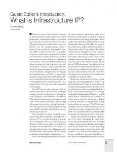
in graph G, and E i (G) is the set of all isolated links in each backup configuration. In our evaluation, we used two different topology models in terms of node-degree. The node-degree expresses the number of links connected to a node. One model is the Waxman model whose node-degree is relatively uniform on each node. The other model is the Barabasi-Albert (BA) model whose node degree follows a power-law. In a power-law network, most nodes have a small number of links while a small portion of nodes have a large number of links. We created 20 instances of topologies using the BRITE topology generation tool [16]. The FR is measured as an average of these 20 instances. A full mesh traffic matrix, which has a uniform 1-Mbps demand, is given. The IP routing is decided based on the shortest metric routing, and metrics of all links are 1, excluding isolated links and restricted links. B. Effectiveness of Algorithm Figure 4 shows the fast recovery ratio for the Waxman model, and Fig. 5 shows the fast recovery ratio for the BA model under a limited available number of backup configurations. In all conditions, our algorithm requires only three backup configurations to achieve 100% fast recovery (FR=1.0) while the conventional algorithm [2] requires from five (20 nodes: Waxman model) to 12 (80 nodes: BA model) backup configurations. In addition, even if available number of backup configuration is limited up to two, recovery ratio with our algorithm keeps more than 90%, while with the conventional algorithm it decreases 17% in the worst case (80 nodes: Waxman model). Because requiring too many backup configurations consumes more network resources, if we place more emphasis on scalability, we may use two backup configurations. The results also suggest that the number of backup configurations with our algorithm does not depend on the number of nodes for each topology model, while the conventional algorithm requires more backup configurations as the number of nodes increases. There was a reduction of up to 72% to achieve 100% fast recovery for the 80 nodes with the BA model. The conventional algorithm ensures that the links and nodes, which could not be isolated in one configuration, are isolated in another configuration by creating the backup configurations simultaneously. Therefore, isolated links tend to be placed around the neighboring position in each backup configuration. The topology, excluding the isolated links in these backup configurations, becomes the sparse topology in local range; therefore, the links in such a range cannot be isolated while the majority of other links can be isolated. The majority of links which are not isolated increases as the network
978-1-4244-4148-8/09/$25.00 ©2009 This full text paper was peer reviewed at the direction of IEEE Communications Society subject matter experts for publication in the IEEE "GLOBECOM" 2009 proceedings.
1.2
1.2
0.8
conventional [2]
0.4
0.2
0
0.8
conventional [2]
0.6
0.4
0.2
5
10
15
20
1
0.8
conventional [2]
0.6
0.4
0.2
0.8
0
5
10
15
0.4
0.2
0 0
20
available number of backup configurations
5
10
15
20
0
available number of backup configurations
(b) N = 40
(a) N = 20
conventional [2]
0.6
0
0 0
available number of backup configurations
proposed
1
1
Fast Recovery ratio (FR)
1
0.6
1.2
proposed
proposed
Fast Recovery ratio (FR)
Fast Recovery ratio (FR)
proposed
Fast Recovery ratio (FR)
1.2
5
10
15
20
available number of backup configurations
(c) N = 60
(d) N = 80
Fig.4. Fast Recovery ratio in Waxman model (the average node degree is 2)
1.2
conventional [2] 0.6
0.4
0.2
0
proposed
1
Fast Recovery ratio (FR)
Fast Recovery ratio (FR)
Fast Recovery ratio (FR)
proposed
0.8
0.8
conventional [2] 0.6
0.4
0.2
0 0
5
1.2
1.2
proposed 1
10
15
20
available number of backup configurations
(a) N = 20
0
5
10
15
20
available number of backup configurations
(b) N = 40
proposed
1
Fast Recovery ratio (FR)
1.2
0.8
conventional [2] 0.6
0.4
0.2
1
0.8
conventional [2]
0.6
0.4
0.2
0
0 0
5
10
15
20
available number of backup configurations
0
5
10
15
20
available number of backup configurations
(d) N = 80
(c) N = 60
Fig.5. Fast recovery ratio in BA model (the average node degree is 2)
size increases. Therefore, the conventional algorithm requires much more backup configurations as the network size increases. In contrast, because our algorithm isolated a certain number of links which are not contained in spanning tree, the dependency to the network size is low. Next, we discuss the dependency to the form of topologies. Our algorithm is effective for each topology model, and it is especially high for the BA model. For example, the difference in the fast recovery ratio using two backup configurations in a 40-node Waxman model is about 25%, while that in a 40-node BA model is about 40%. This is due to the distribution of the link load. By our observation, the average link loads with the BA model vary from 4 to 112 Mbps, while the average link loads with the Waxman model vary from 6 to 84 Mbps. This means that the variance of link loads with the BA model is higher than that with the Waxman model because the BA model has an inhomogeneous node-degree distribution. Therefore, our algorithm, which isolates links whose link loads are high in priority, works well. Because network topologies of major ISPs often show the tendency of power-law [16], our algorithm is applicable on actual networks. C. Overhead of Algorithm First, we discuss the characteristics of backup routes based on our backup configurations. The ratio of available links to all links in backup configurations decreases to the reciprocal of average node degree [11]. Therefore our configurations lead to longer backup paths and less available bandwidth. However, this features are not as important as the number of backup configurations required because the backup routes, which are calculated by the backup configurations, are used only for
traffic crossing a failed resource. The traffic that does not use failed resources is forwarded according to the original configuration. Moreover, these routes are only used until the backup routes are calculated by the link-state protocol. Therefore, the impact of available resources reduction is low. Next, we discuss the computation time of our algorithm. The time for 20 iterations (M=20) of our algorithm was about 14 seconds for 80 nodes using a C++ program on a Xeon 2.9-GHz PC with 128 GBytes of memory. Although the computation time increases in proportion to the number of iteration times, the number of backup configurations converges in 20 iterations under all conditions. Our algorithm is relatively complex compared to the simpler conventional algorithm [2], but it is reasonable to suggest that this tendency of computation time, which should be computed offline, is acceptable. V. RELATED WORK In this section, we summarize other IP Fast Reroute techniques [3-10]. IP Fast Reroute techniques, which also use backup configurations, have been proposed [3-5]. Hansen et al. [3] proposed a backup configuration computation algorithm considering multiple failures. Kvalbein et al. [4] reduced the length of the detour paths by optimizing the metrics in backup configurations. However, they do not consider the presented problem. Cicic et al. [5] proposed an algorithm to reduce the number of backup configurations. However, their algorithm requires the extension of another information table called a last-hop recovery table for fast recovery. Therefore, it is not suitable for the current multiple topology routing architecture
978-1-4244-4148-8/09/$25.00 ©2009 This full text paper was peer reviewed at the direction of IEEE Communications Society subject matter experts for publication in the IEEE "GLOBECOM" 2009 proceedings.
[12, 13]. A loop free alternate (LFA), which does not require extensions to existing link-state routing protocols to set the proper link metrics, has been proposed [6]. The node, which detects a failure, forwards the IP packets to the node called the LFA, which is not the original next hop. The link metrics are set so that the route from the LFA to the destination node does not include the node detecting the failure. Therefore, routing loops never occur. The drawback of these techniques is that they cannot handle a single failure in an arbitrary form of the topology because the routes based on link metrics depend on the topology [14]. Nelakuditi et al. [7] proposed an IP Fast Reroute technique called failure insensitive routing (FIR) .The key point of FIR is that a failure point is estimated from the relationship between the destination IP address and the incoming interface. If packets are received on an irregular interface, which is connected with the next hop node on the shortest path to the destination, the router interprets that a failure has occurred on the shortest path. The advantage of this estimating approach is that there is no need to advertise the failure point. However, FIR cannot handle arbitrary multiple failures. FIR is extended to handle node failure [8] and to work on an inter-domain environment [9]. A not-via address approach was proposed [10]. In this approach, IP packets are encapsulated, and a header is added to the packet. This header contains the not-via address. The encapsulated packets detour the failure points because the route for not-via address is precomputed to avoid the failure points. First, a failure-detecting node encapsulates the IP packets to give the not-via address. All nodes forward the packets according to the not-via address. If these packets arrive at nodes located downstream of the failure points, the header with the not-via address is removed, and the IP packets are forwarded according to the original destination address. The detour route can be calculated flexibly with respect to each not-via address, but routers need to maintain the next hop according to the not-via addresses. VI. CONCLUDING REMARKS Multiple Routing Configurations is a powerful tool for achieving robustness in an IP network. On the other hand, requiring too many backup configurations consumes more network resources. If the available resources of the routers are limited, fast recovery cannot take place for certain arbitrary single failures because all backup configurations cannot be installed in the router. Therefore, it is necessary to recover traffic flows as much as possible with fewer backup configurations. We presented a new backup configuration creation algorithm for maximizing traffic flows that are fast recovered as much as possible under a limited number of backup configurations. We demonstrated its effectiveness through an extensive simulation study. The results showed that our algorithm recovers traffic flows with fewer backup configurations than with the conventional algorithm. The
number of configuration generated by our algorithm is low-dependent to the network size. Moreover, our algorithm is effective for various topology models, and it is especially high in power-law networks. That is, our algorithm is more feasible for achieving robustness on actual large IP networks. REFERENCES [1]
J. Moy, ”OSPF Version 2,” IETF RFC 2328, April 1998.
[2]
A. Kvalbein, A. F. Hansen, T. Cicic, S. Gjessing, and O. Lysne, “Fast IP Network Recovery using Multiple Routing Configurations,” in Proceedings of INFOCOM, Apr.2006
[3]
A. F. Hansen, O. Lysne, T. Cicic, S. Gjessing, “Fast Proactive recovery from Concurrent Failures,” In Proceedings IEEE International Conference on Communications, ICC 2007, June 2007.
[4]
A. Kvalbein, T. Cicic and S. Gjessing, “Post-Failure Routing Performance with Multiple Routing Configurations,” INFOCOM, May 2007.
[5]
T. Cicic, A. F. Hansen, A. Kvalbein, M. Hartmann, R. Martin, and M. Menth, "Relaxed Multiple Routing Configurations for IP Fast Reroute," In IEEE/IFIP Network Operations and Management Symposium 2008.
[6]
A. Atlas and A. Zinin, “Basic specification for IP fast reroute: Loop-free alternates,” IETF RFC 5286, Sep. 2008.
[7]
S. Nelakuditi, et al., "Failure Insensitive Routing for Ensuring Service Availability," IW QoS', June 2003.
[8]
Z. Zhong, S. Nelakuditi, Y. Yu, S. Lee, J. Wang, and C.-N. Chuah, “Failure inferencing based fast rerouting for handling transient link and node failures,” in Proceedings of IEEE Global Internet, vol. 4, Mar. 2005.
[9]
J. Wang, and S. Nelakuditi, “IP Fast Reroute with Failure Inferencing,” In Proceedings of INM'07, at ACM SIGCOMM, Aug. 2007.
[10] M. Shand, et al., “IP Fast Reroute Using Not-via Addresses,” IETF draft-ietf-rtgwg-ipfrr-notvia-addresses-04 Jul 2009. [11] S. Kamamura, T.Miyamura, C. Pelsser , I.Inoue, K.Shiomoto, “Scalable Backup Configurations Creation for IP Fast Reroute,” IEEE Design of Reliable Communication Networks (DRCN) Oct 2009. [12] P. Psenak, S. Mirtorabi, A.Roy, L. Nguen, and P. Pillay-Esnault, “MT-OSPF: Multi topology (MT) routing in OSPF,” IETF, RFC4915, June 2007. [13] T. Przygienda, N. Shen, and N. Sheth, “M-ISIS: Multi topology (MT) routing in IS-IS,” Internet Draft (work in progress), Oct. 2005, draft-ietf-isis-wg-multi-topology-11.txt. [14] M. Gjoka, V. Ram, Y. Xiaowei, "Evaluation of IP Fast Reroute Proposals," COMSWARE Jan. 2007. [15] Joseph. B. Kruskal, “On the Shortest Spanning Subtree of a Graph and the Traveling Salesman Problem,” In Proceedings of the American Mathematical Society, Vol. 7, No. 1 (Feb, 1956), pp. 48–50 [16] A. Medina, A. Lakhina, I. Matta, J. Byers, “BRITE: An approach to universal topology generation,” IEEE MASCOTS, Aug. 2001
978-1-4244-4148-8/09/$25.00 ©2009 This full text paper was peer reviewed at the direction of IEEE Communications Society subject matter experts for publication in the IEEE "GLOBECOM" 2009 proceedings.