Sep 5, 2004 - These traces are presented to the software engineer together with ..... It is worth to note that the listed change traces are in descending order.
Mining Change Traces from Versioned UML Repositories♣ Cristine Dantas
Leonardo Murta
Cláudia Werner
COPPE/UFRJ – Systems Engineering and Computer Science Program Federal University of Rio de Janeiro – P.O.Box 68511- 21945-970 Rio de Janeiro, Brazil {cristine, murta, werner}@cos.ufrj.br
Abstract. As software evolves, analysis and design models should be modified, correspondingly. In this scenario, one of the main problems is to detect which elements should be changed due to a given change. This paper presents an approach that applies data mining over a versioned UML repository in order to detect change traces among model elements at different abstraction levels. These traces are presented to the software engineer together with context information obtained from SCM systems and used within CASE tools. We also present the results of a retrieval performance evaluation of our approach, which are promising.
1. Introduction The software development process encompasses many distinct phases, each of them working on a specific abstraction level. This multi-level structure is important to model and refine the knowledge about an application domain, providing control over the complexity of software development. In this scenario, UML notation is a strong candidate for representing analysis and design artifacts (Page-Jones, 1999). However, software engineers must ensure that all UML artifacts are up to date and consistent throughout the different abstraction levels to avoid misunderstandings. Traceability techniques can be used to solve this problem by identifying all UML model elements that shall be updated when a change is introduced (Cleland-Huang and Chang, 2003). Software artifact traceability is an important factor at analysis and design levels which helps software engineers to identify bad design decisions early on the software development process and provides a high level view of the system dependencies (Settimi et al., 2004). In this context, traceability links are semantic relationships among software artifacts (Kowalczykiewicz and Weiss, 2002). There are some automated approaches to ♣
This paper is an extended version of a four-page position paper named “Consistent Evolution of UML Models by Automatic Detection of Change Traces”, published at the 8th International Workshop on Principles of Software Evolution, Lisbon, September 2005. This paper complements the position paper with a more detailed presentation of the proposed approach, a usage example, and an evaluation.
keep traceability links updated during software evolution. These approaches are based on three major techniques: syntactic analysis (Briand et al., 2003), information retrieval (Antoniol et al., 2002; Huffman Hayes et al., 2003; Marcus and Maletic, 2003; Settimi et al., 2004), and data mining (Shirabad et al., 2001; Ying et al., 2004; Zimmermann et al., 2004). The approaches that use syntactic analysis consider the software structure to identify the interrelations among the artifacts. The information retrieval approaches for traceability link detection and evolution rely on the assumption that the same concepts and terms are used to describe correlated artifacts. Both kinds of approaches do not take into account the historical information of software evolution to detect traceability links, as presented in Figure 1. Syntactic analysis
Structure Terms
Information retrieval
Data mining
Traceability links
Evolution history
Time
Now Figure 1. Traceability detection techniques
On the other hand, the approaches based on data mining techniques usually search for concomitant changes in Software Configuration Management (SCM) systems to discover possible dependencies among software artifacts. SCM techniques are commonly used to control the evolution of software systems by providing versioning, via Version Control Systems (VCS), and support for activities related to change management, via Change Control Systems (CCS). The advantage of this kind of approach is that data mining techniques will recognize that two elements are always changed together even if there are no design relationships or similar terms between these two elements. For this reason, this kind of approach can possibly be used to detect bad design decisions. The data mining technique named association rules (Agrawal and Srikant, 1994) searches for patterns that determine the dependency between two or more elements inside a database. Table 1 shows how each data mining term can be related to a classical data mining domain (i.e., supermarket) and software evolution domain, used by our approach. Table 1. Data mining terminology Context Supermarket Software evolution
Item Product UML model elements
Transaction Sale Change
Database Mining Result Purchase database Customer preference UML repository Change traces
In the classical usage context of data mining, all sales are analyzed to detect buying patterns among different customers. These patterns indicate which items are frequently purchased together. In our approach, items are represented by UML model elements. Therefore, the mined database is a versioned UML repository that stores changes
performed during the development and maintenance phases. In this context, change traces are defined as traceability links obtained from change information. Moreover, each database transaction is represented by a change implemented via one or more check-in operations. The goal of this work is to detect UML model elements that were changed together in the past and will probably need to be changed together in the future, and to justify the detected UML model elements. Our approach fulfills the two main aspects discussed in this section: (1) the automatic detection of change traces among UML model elements (using the association rules technique), and (2) the externalization of the rationale that explains the existence of the change traces. It is worth to note that this work is not focused on applying data mining over a specific project, but providing an approach that automates this process and presenting some evaluation of this approach. This paper is organized in five sections besides this introduction. Section 2 describes our approach for change traces detection via data mining techniques over versioned UML repositories. Section 3 shows a usage example of our approach, followed by a retrieval performance evaluation, presented in Section 4. Section 5 presents some related works. Finally, Section 6 concludes the paper with the contributions and limitations of our approach, and presents some future works.
2. Detecting change traces This section introduces our approach for change traces detection among UML model elements. This approach was implemented as a standalone tool and as a plug-in of an existing software development environment named Odyssey (Werner et al., 2003). Odyssey environment provides support for domain engineering and application engineering based on UML, among other notations, to describe domain models. Our approach can support other XMI-based CASE tools via the implementation of additional plug-ins. Our approach assumes that the project under analysis applies SCM as an ordinary practice, with a CCS being used to control changes lifecycle and a VCS being used to version control UML model elements. Moreover, our approach assumes that both CCS and VCS work over an integrated SCM repository, which links change requests to the versions of UML model elements that were created to implement them. The current implementation of our approach uses a CCS named Odyssey-CCS (Lopes et al., 2006) to control changes lifecycle and a VCS named Odyssey-VCS (Oliveira et al., 2005) to version control UML model elements. Besides the current implementation, our approach could be implemented over other CCSs and VCSs that fulfills the requirements described in the previous paragraph. Odyssey-CCS provides process and information customization, which allows configuration managers to model the SCM process and to define which information needs to be collected by each activity of the modeled SCM process. This definition is done via templates and fields creation. Each activity is associated to a set of templates, and each template is composed of a set of fields. For a given template and field, Odyssey-CCS is able to inform the value that was filled in during the execution of a specific SCM activity.
Odyssey-VCS has, as one of its benefits, the feature of flexible configuration item granularity. This feature allows the selection of the desired granularity of configuration items for version control. For example, a given project can use broader elements as configuration items, such as packages, or narrowed elements, such as attributes or operations. The configuration item granularity determines which elements will be versioned during the SCM process. For this reason, the granularity of the traced UML elements depends on the configuration of the Odyssey-VCS. This section is organized into three sub-sections, which explain what change traces are, the rationale regarding their existence, and how the detection process shall occur. 2.1. Change traces Throughout the lifecycle of a project, software artifacts are changed when new features are added, old ones are enhanced, or bugs are fixed. In the CCS, changes have a predefined lifecycle, determined by the SCM activities (IEEE, 2005): (1) change request, (2) classification, (3) impact analysis, (4) evaluation, (5) implementation, (6) verification, and (7) integration. During the implementation activity of this lifecycle, different software artifacts are modified to perform the change. Each version of the modified artifacts is stored in the VCS. Along with the versioned artifacts, other valuable information is kept by the VCS, such as message, author, and date of each check-in operation performed during the implementation of a change. The integrated SCM repository allows the detection of which artifacts are affected by a given change. Moreover, it offers an opportunity to gain some insight about change rationale (Hassan and Holt, 2003). As the number of change requests grows, it is possible to detect, in the intersection of each change, elements that are always changed together. Figure 2 shows the two types of change traces that can be obtained by our approach: intra-model and inter-model. Change request
Change Control System
Intra-model traces
Version Control System
Analysis Inter-model traces Design
Code Figure 2. Change Traces
The intra-model change trace relates two or more elements in the same abstraction level. For example, it is possible to detect that some classes are always changed together. On the other hand, inter-model change trace relates two or more elements in different abstraction levels. For example, it is possible to detect that a use case and a class are often changed together.
2.2. Change traces rationale While developers investigate change traces, they pose various questions to uncover the rationale of dependencies that were identified. Currently, most approaches that support change traces detection lack to provide the semantics of the change traces among software artifacts (i.e. rationale). To minimize this problem, our approach provides a view of all detected change traces and the details about the rationale, the history, and the people behind them. Such details are vital in assisting developers to understand the current state of the software system throughout the evolution process (Hassan and Holt, 2003). This rationale follows an information structure widely used in the Computer Supported Cooperative Work field to contextualize and provide knowledge about elements (Gutwin and Greenberg, 2002). This information structure is known as 5W+1H and comprises the following pieces of information: who, when, where, why, what, and how (see Figure 3). change trace
Model Element “Reservation Class”
Model Element “Hotel Class”
Who has changed it? When was it changed? Where was it changed? Why was the change requested? What has been changed? How was the change performed?
Figure 3. Change traces rationale
The Who question is attributed to the person responsible for the implementation of the previous changes. This person is capable of answering questions about future implementations. The When question has the implementation date of the previous changes. This information gives an idea about how recent the previous implementations are. The Where question defines the artifacts impacted by the previous changes. The What question explains what was done to implement the previous changes. The Why question is related to the reason of the previous changes. Finally, the How question is related to the strategies of implementation of the previous changes. In practice, manually gathering such information is counterproductive and error prone (Hassan and Holt, 2003). On the other hand, SCM repositories store change details obtained from the SCM activities described in Section 2.1. These change details are automatically collected and organized by our approach to provide the required 5W+1H information, as shown in Table 2. The automatic gathering of 5W+1H information depends on an integrated SCM repository. This integrated SCM repository is automatically analyzed to collect the rationale information shown in Figure 3. 2.3. Change traces detection The process for change traces detection comprises two main phases: configuration and querying. The configuration phase is when the configuration manager sets the desired
data mining metrics and informs the templates and fields of the CCS that should be used to collect rationale information, as mentioned in Table 2. The querying phase occurs when developers want to know the change traces among UML model elements. Usually, a UML model element is selected and all change traces from this element are provided. This mechanism helps to answer questions such as “Developers that change a given element also change which other elements?”, providing support for the developers’ future changes. Table 2. Rationale gathering Information Type
Collection Place
Who
− −
Check-in information from VCS Implementation activity from CCS
When
− −
Check-in information from VCS Implementation activity from CCS
How
−
Impact analysis from CCS
Why
−
Change request activity from CCS
What
− −
Check-in information from VCS Verification activity from CCS
Where
−
Check-in information from VCS
It is important to notice that this approach does not intend to replace the work of software engineers. Since change traces are based on past experience, they do not constitute absolute truth, but suggestions. To categorize the relevance of these suggestions, each change trace has a probabilistic interpretation based on the amount of evidence from the data that they are derived from. This evidence can be represented by two data mining metrics: support and confidence. According to Agrawal and Srikant (1994), the rule X � Y has support s if s% of transactions contain X U Y. Moreover, the rule X � Y holds with confidence c if c% of transactions that contain X also contain Y. In our context, support quantifies the cooccurrence of artifacts in implemented changes (joint probability) and confidence quantifies the co-occurrence of artifacts in implemented changes given that other artifacts also occur (conditional probability). Typically, association rules techniques are interested in rules that satisfy both minimum support and confidence thresholds. The process for mining change traces comprises two steps: (1) selection of changes that will be analyzed, and (2) mining the transactions, searching for rules that describe relationships between UML model elements. To select changes to be analyzed, our approach verifies: (1.1) if the change is already concluded, (1.2) if the change has affected UML model elements older than the UML model element that is being queried by the developer, and (1.3) if the change affects the UML model element that is being queried by the developer. After that, data mining is applied over the changes selected according to the above conditions. The data mining algorithm, based on Apriori algorithm (Agrawal and Srikant, 1994), calculates the support and confidence metrics for each pair of artifacts that are included in the changes and, then, prunes the elements with support and confidence lower than the minimum thresholds. For example, assume that our SCM repository has 3 completed changes: C1, affecting the UML model elements A and B; C2, affecting the UML model elements A,
B, and C; and C3, affecting UML model elements A, C and D. On one hand, our approach could find that “developers that change B also change A” with 66% of support and 100% of confidence. This can be analyzed as follows: 2 out of 3 existing changes affected B and A together (which means 66% of support), and all (2 out of 2) changes that affected B also affected A (which means 100% of support). On the other hand, our approach could find that “developers that change B also change C” with 33% of support and 50% of confidence. This can be analyzed as follows: 1 out of 3 existing changes affected B and C together (which means 33% of support), and 1 out of 2 changes that affected B also affected C (which means 100% of support). With this very simple but illustrative example we can note that the first rule (“developers that change B also change A”) is more probable than the second one (“developers that change B also change C”). In real situations the number of changes grows considerably, and the distinction between probable rules and improbable rules also tend to increase. The minimum threshold serves as a mechanism to avoid these improbable rules. Our approach presents, together with the mined change traces, the 5W+1H information based on the CCS configuration (Table 2) and collected from previous changes in the integrated SCM repository that were used in the mining process.
3. Usage Example This usage example shows how the proposed approach works. The goal of this usage example is not to apply our approach over a real project (this is provided in the evaluation section), but to illustrate how the approach works using a simple example. The model used in this example has the following components and classes, among other model elements (Figure 4): the “Guest” component is implemented by the “Client” and the “Guest” classes; the “Hotel” component is implemented by the “Hotel” and the “Room” classes; the “Reservation” component is implemented by the “Reservation” class; and the “RoomType” component is implemented by the “RoomType” class. 1
2
3
4
2 1
3
4
Figure 4. Use case, class, and component diagrams used in the example
The change requests, which intend to provide some basic required features for the system, are listed in Table 3. Table 3. Change requests Change #1
Description Verify, during the reservation, the availability of rooms for the desired period.
#2
Show the room type, features, and price when the reservation is queried.
#3
Search for rooms in other hotels in the same area if there is no room available.
#4
Do not allow double reservations on the same room at the same period.
#5
Make the room available if the reservation is canceled.
#6
Show previously reserved hotels as preferred options.
During the implementation phase of the change lifecycle, some artifacts are created or modified using Odyssey-VCS. Table 4 shows all created or modified artifacts to accomplish the implementation of each change listed in Table 3. These artifacts are shown together with their final versions. It is worth to mention that the relationship among change requests and changed artifacts is possible due to the integrated SCM repository. Table 4. Modified artifacts Change
Modified Artifacts
#1
Use Cases: Make Reservation (v1). Classes: Client (v1), RoomType (v1), Room (v1), Hotel (v1), Reservation (v2), Guest (v1). Components: Reservation (v2), Hotel (v1), Guest (v1), RoomType (v1).
#2
Use Cases: Query Reservation (v3). Classes: RoomType (v3), Reservation (v3). Components: Reservation (v3), RoomType (v3).
#3
Use Cases: Make Reservation (v4). Classes: Hotel (v4), Reservation (v4). Components: Reservation (v4), Hotel (v4).
#4
Use Cases: Make Reservation (v5). Classes: Hotel (v5), Reservation (v5). Components: Reservation (v5), Hotel (v5).
#5
Use Cases: Cancel Reservation (v6). Classes: Hotel (v7), Reservation (v6). Components: Reservation (v6), Hotel (v7).
#6
Use Cases: Query Hotels (v8). Classes: Hotel (v8), Guest (v8). Components: Hotel (v8), Guest (v8).
As discussed before, our approach comprises two phases: configuration and querying. At the configuration phase, it is possible to select threshold values for the support and confidence metrics and to define the 5W+1H information gathering with templates and fields of Odyssey-CCS, as shown in Figure 5. Support may be defined in a continuous domain with minimum and maximum boundaries equal to 0 and 1 (i.e. 0% and 100%), respectively, or in absolute values. Confidence is always defined in a continuous domain from 0% to 100%. Although high threshold values of support and confidence tend to detect fewer change traces, they also
tend to be more accurate. On the other hand, low threshold values of support and confidence provide a huge amount of change traces, with many false positives. (b)
(a)
Figure 5. Support and confidence (a), and rationale gathering (b) configuration
Our experience shows that support and confidence threshold should start with high values for new projects, and have their values decreased to a stationary position. In a small database, each element has a huge influence in the support and confidence values, increasing the number of false positives change traces. On the other hand, in a large database, an individual element has almost no influence in the value of support and confidence, allowing the reduction of support and confidence thresholds. In this usage example, the data mining metrics have support and confidence threshold values set to 50% (or 3, in absolute value) and 60%, respectively. The meaning of these metrics is that the queried artifact has been changed together with the traced artifacts in at least 50% of all existing changes, and the traced artifacts have been changed in at least 60% of the changes that affect the queried artifact. Assuming that our tool was properly configured, the next phase consists of querying change traces for a given queried artifact. In this example, the queried artifact is the “Reservation” class (see Figure 6). Besides the change trace to the model itself, which is always modified, the “Reservation” component is the most impacted artifact, with 100% of confidence. Moreover, other change traces are detected for the “Hotel” class and the “Hotel” component, with 80% of confidence. Change traces to other artifacts are also detected. However, the support or confidence is lower than 50% and 60%, respectively. At a first glance, these change traces can be expected by the developer. However, in a real usage scenario, the number of changes implemented in the system is greater than 6, as presented in this simple example to clarify the mechanisms behind our approach. With a huge amount of UML model elements being changed, our approach becomes more relevant, detecting change traces that would hardly be detected by manual approaches. It is worth to note that the listed change traces are in descending order
regarding support. This strategy provides to the user the more relevant change traces first, but the remaining relevant change traces can be accessed via scrolling.
Figure 6. Detected change traces
In this example, change traces show which artifacts have been changed together with the "Reservation" class. Based on this information, the developer can decide if the mined artifacts will be changed together or not. The rationale provided together with the change traces is an important instrument to help in this decision. By analyzing this simple usage example we can verify that the approach can contribute to the impact analysis activity, avoiding under-prediction of the scope of a change and helping to identify critical side-effects. Also, it can indicate anomalies in the design structure which may be subject to restructuring. For example, if the “Reservation” class of the “Reservation” component is always changed together with a class of the “Hotel” component, then the architecture design probably presents inconsistencies, allowing high coupling between these two classes.
4. Evaluation In this section we present an evaluation of the retrieval performance of our approach. The retrieval performance of our approach is objectively evaluated via some traditional information retrieval measures, which indicate how accurate the approach is in terms of how many correct change traces are retrieved and how many incorrect change traces are retrieved (Settimi et al., 2004). A good approach is supposed to retrieve a high number of correct change traces without adding undesired noise (incorrect change traces) to the results. This evaluation consists on a retrospective study over an existing system, named Odyssey (Werner et al., 2003). Odyssey is a medium size software development environment under development at COPPE/UFRJ since 1997 (around 60,000 NCLOCs). However, Odyssey does not have complete versions of UML models available. For this
reason, we decided to reverse engineer the source-code to reconstruct the UML model of each source-code configuration. This allows a fair analysis over the evolution of the Odyssey system in a short-term period. Another important advantage of this strategy regards biases. The study was not even designed during Odyssey development. For this reason, the study results cannot be biased by actions taken at that time. To perform this study, we gathered Odyssey versioning data produced during the period of November 26, 2003 until March 1, 2005, totalizing more than 15 months of development and containing 264 check-ins. This data was reorganized, reverse engineered, and divided into two sets: training set and evaluation set. The training set is composed of 160 check-ins dating from November 26, 2003 until September 5, 2004, totalizing more than 9 months of development. The evaluation set is composed of 104 check-ins dating from September 8, 2004 until March 1, 2005, totalizing around 6 months of development. The 160 source-code check-ins originally in the training set, and the 104 sourcecode check-ins originally in the evaluation set were converted after the reverse engineering step into 38 and 34 check-ins of UML models, respectively. This situation occurs because some source-code check-ins do not represent changes in UML models. For example, when a method is changed, the changed code may only affect already imported classes, not creating new dependencies in the UML model. Due to that, a new configuration (check-in) of UML model is not generated. In our case, a UML model change occurred for each 3.66 changes in source-code. This means that there is less historical information available during a given period of time when dealing with models. As a consequence, only changes that really affect the high-level structure of the system are considered. This may explain the differences in precision and recall of our approach if compared to existing file-based approaches. Moreover, our approach may be used during analysis and design phases, where no source-code is available yet. Some restrictions were applied to the Odyssey historical data before performing the evaluation to reduce possible confounding factors. First, only UML classes were processed. Classes are composed by attributes and operations. When an operation is modified, the class that owns the operation is also changed. This composition rule would improperly increase the performance of our approach. For instance, it is useless to know that “class ‘C’ is changed when attribute ‘A’ of class ‘C’ is changed” (that is obvious!). An analogous situation may occur regarding packages and classes. For this reason, we decided to avoid composition structures in our evaluation and only focused on elements of the same type: classes. However, our approach is not restricted to this element type. Finally, only model elements that were changed at least once in the training set and in the evaluation set were processed. After this preparation phase, our tool was executed over the training set for each model element. The detected change traces represent predictions provided by our tool on September 5, 2004. These predictions were compared to real changes performed in the evaluation set, aiming to know if the predictions really occurred (somewhere in between September 8, 2004 and March 1, 2005). The results are presented in the following in terms of traditional information retrieval measures (Baeza-Yates and Ribeiro-Neto, 1999), such as precision, recall, Rprecision and harmonic mean. Precision indicates how much our predictions were cor-
rect and recall indicates how much correct change traces were predicted. The remaining measures provide the notion of precision after a fixed number of change traces are retrieved (R-precision) and the best compromise between recall and precision for given values of support and confidence (harmonic mean). The evaluation was performed according to the “Retrieval Performance Evaluation” procedures described by Baeza-Yates and Ribeiro-Neto (1999). Initially, we performed a precision x recall analysis of the retrieved change traces. In our context, the precision measure consists in the fraction of retrieved change traces which is relevant. On the other hand, the recall measure consists in the fraction of relevant change traces which has been retrieved: Precision =
Relevant ∩ Retrieved Retrieved
Recall =
Relevant ∩ Retrieved Relevant
Our tool was queried for each existing model element in the training set. The detected change traces were ranked by higher support and confidence (more relevant first). After that, the precision and recall were calculated for each relevant change trace, starting from the top of the ranked result. A change trace is considered relevant if the traced model element is also modified together with the queried model element in the evaluation set. Subsequently, an interpolation procedure was applied to determine precision values for each of the 11 standard recall levels, which goes from 0 up to 1, stepped by 0.1. The interpolation function establishes the precision at a given recall level as the maximum value of any available precision in between the current and the next recall level, inclusive. Finally, the precision and recall values already calculated for each single query were combined according to an average function. This function consists in establishing an average precision value for each recall level: queries
Precision(Recall[level]) =
∑ query=1
Precisionquery (Recall[level ]) queries
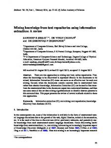
The results of precision x recall analysis are presented in Figure 7.a. This curve shows that a precision of roughly 65% is obtained at 10% recall. In other words, 2 in every 3 suggestions of our approach were correct to detect the first 10% relevant change traces. Moreover, a precision around 33% is obtained at 50% recall. Finally, a precision about 4% is obtained at 100% recall. These results are impressive if compared to existing results regarding file-based artifacts. For instance, the average results regarding the Eclipse IDE are precision around 30% (Ying et al., 2004) or 26% (Zimmermann et al., 2004) at 15% recall. In our case, we reached precision around 60% at 15% recall. Although promising, it is important to use discretion when directly comparing these numbers. Odyssey and Eclipse IDE are different systems, with different complexity and different development processes. Besides the importance of average precision x recall curves as a standard evaluation strategy, it is also desired to visualize the results as a single numerical value. The Rprecision measure computes the precision at the Rth position of the ranked list of retrieved change traces, where R is the total number of relevant change traces for the cur-
rent query. For example, if an element has a total of 5 relevant change traces but only 1 of these is detected among the first 5 retrieved change traces, then R-precision = 20%. After calculating R-precision for each individual query, a histogram was drawn to describe the number of queries that belong to a specific R-precision range. This histogram, depicted in Figure 7.b, shows that five queries could find half of the relevant change traces among the first R retrieved change traces. (b) 6
60% 50% 40% 30% 20% 10% 0%
5 Frequence
Precision
(a) 70%
4 3 2 1 0
0%
20%
40% 60% Recall
80%
0%
100%
10%
20% 30% 40% R-Precision
50%
Figure 7. (a) Precision x recall curve and (b) R-Precision histogram
Finally, we would like to know the best threshold values of support and confidence that produce optimal combination of precision and recall in our context. The harmonic mean measure can help in this task by attempting to provide the best compromise between precision and recall for given values of support and confidence: HarmonicMean =
2 1 1 + Recall Precision
The average harmonic mean of precision and recall is plotted in Figure 8 for specific values of support and confidence. This shows that maximum harmonic mean values, indicating the best compromise of precision and recall, are obtained for low support and confidence values. This kind of analysis should be performed to any target system to help configuring the support and confidence values in the tool. Harmonic Mean
40% Support = 1
30%
Support = 2 20%
Support = 3
10%
Support = 4 Support = 5
0% 0%
20%
40% 60% Confidence
80%
100%
Figure 8. Harmonic mean of precision and recall in terms of support and confidence
The summary of statistics discussed in this section is presented in Error! Reference source not found. for each query at minimum support = 1 (any confidence). It shows the query number, the precision, recall, R-precision, and harmonic mean of precision and recall metrics.
Table 5. Statistics summary Query # 1 2 3 4 5 6 7 8 9 10 11 12 13 14 15
Relevant 3 12 10 6 6 5 2 11 11 4 4 12 3 0 9
Retrieved 3 5 7 3 3 3 3 0 2 2 2 4 12 19 19
Rel. ∩ Ret. 0 3 2 3 3 2 2 0 2 2 2 3 1 0 3
Precision 0% 60% 29% 100% 100% 67% 67% 0% 100% 100% 100% 75% 8% 0% 16%
Recall 0% 25% 20% 50% 50% 40% 100% 0% 18% 50% 50% 25% 33% 0% 33%
R-Precision 0% 25% 20% 50% 50% 40% 50% 0% 18% 50% 50% 25% 0% 0% 11%
H-Mean 0% 35% 24% 67% 67% 50% 80% 0% 31% 67% 67% 38% 13% 0% 21%
5. Related Work In the last decade, researchers have experienced the use of SCM repositories to understand software evolution. Gall et al. (1997) use release data to detect logical coupling between modules. Ball et al. (1997) have performed some cluster analysis of C++ classes stored in SCM repositories. Other works (Shirabad et al., 2001, Zimmermann et al., 2004, Eick et al., 2001) also perform historical analysis over SCM repositories. Shirabad et al. (2001) use inductive learning to find out different concepts of relevance among logically coupled files. Eick et al. (2001) argue that code decay is related to the difficulty to perform changes. For this reason, they analyze change history applying decay indexes to identify risk factors. Draheim et al. (2003) argue that product quality is dependent of process quality. Due to that, the development process activities are analyzed and some metrics are applied over the VCS. Finally, Zimmermann et al. (2004) have evidenced that mining SCM repositories can be useful for predicting likely further changes, detecting hidden dependencies, and preventing incomplete changes. However, these related researches work over file-based SCM repositories. For this reason, they lack support for change traces detection of fine-grained UML model elements and cannot be applied on early phases of the software development lifecycle. Moreover, they do not provide change traces rationale, automatically gathered from an integrated SCM repository. This change traces rationale is the main mechanism for helping developers to understand the reason of existence of the change traces.
6. Conclusion This paper presented an approach for the detection of change traces among UML model elements. This approach was implemented by a tool available at http://www.cos.ufrj.br/~murta/Odyssey-SCM. Some contributions of our approach are: (1) automatic change traces detection; (2) use of UML model elements as mining units, leveraging the state of the art to fine-grained analysis and design artifacts; (3) description of change traces rationale using 5W+1H structure, automatically collected from an
integrated SCM repository. It is worth noting that to the best of our knowledge there are not approaches that apply data mining over UML model elements, nor automatically gather change traces rationale. Some of our future work includes the extension of the proposed approach to other MOF-based meta-models, besides UML, and the summarization of the reasoning information. Another future works is to consider the source-code changes together with the architectural changes during the change traces detection phase. Moreover, to apply, together with data mining techniques, information retrieval and syntactic analysis techniques during the change traces detection phase. Finally, we intend to perform future evaluations to verify if this approach is scalable and other case studies to verify how the benefits and limitations of our approach affect the maintenance tasks in a real usage scenario.
References Agrawal, R., Srikant, R., 1994, "Fast Algorithms for Mining Association Rules in Large Databases". In: International Conference on Very Large Data Bases (VLDB), pp. 487-499, Santiago de Chile, Chile, September. Antoniol, G., Canfora, G., Casazza, G., et al., 2002, "Recovering Traceability Links between Code and Documentation", IEEE Transactions on Software Engineering (TSE), v. 28, n. 10 (October), pp. 970-983. Baeza-Yates, R., Ribeiro-Neto, B., 1999, Modern Information Retrieval, ACM Press. Ball, T., Kim, J., Porter, A.A., et al., 1997, "If your version control system could talk". In: Workshop on Process Modelling and Empirical Studies of Software Engineering, Boston, MA, USA, May. Briand, L.C., Labiche, Y., O'Sullivan, L., 2003, "Impact Analysis and Change Management of UML Models". In: International Conference on Software Maintenance (ICSM), pp. 256-265, Amsterdam, Netherlands, September. Cleland-Huang, J., Chang, C.K., 2003, "Event-Based Traceability for Managing Evolutionary Change", IEEE Transactions on Software Engineering (TSE), v. 29, n. 9 (September), pp. 796-810. Draheim, D., Pekacki, L., 2003, "Process-Centric Analytical Processing of Version Control Data". In: International Workshop on Principles of Software Evolution (IWPSE), pp. 131-136, Helsinki, Finland, September. Eick, S.G., Graves, T.L., Karr, A.F., et al., 2001, "Does code decay? Assessing the evidence from change management data", IEEE Transactions on Software Engineering (TSE), v. 27, n. 1 (January), pp. 1-12. Gall, H., Jazayeri, M., Klösch, R., et al., 1997, "Software Evolution Observations based on Product Release History". In: International Conference on Software Maintenance (ICSM), pp. 160-196, Bari, Italy, October. Gutwin, C., Greenberg, S., 2002, "A Descriptive Framework of Workspace Awareness for Real-Time Groupware", Journal of Computer Supported Cooperative Work, v. 11, n. 3, pp. 411-446.
Hassan, A.E., Holt, R.C., 2003, "ADG: Annotated Dependency Graphs for Software Understanding". In: Visualizing Software For Understanding And Analysis, pp. 4145, Amsterdam, Netherlands, September. Huffman Hayes, J., Dekhtyar, A., Osborne, J., 2003, "Improving Requirements Tracing via Information Retrieval". In: International Conference on Requirements Engineering (RE), pp. 138-147, Monterey, USA, September. IEEE, 2005, Std 828 - IEEE Standard for Software Configuration Management Plans, Institute of Electrical and Electronics Engineers. Kowalczykiewicz, K., Weiss, D., 2002, "Traceability: Taming uncontrolled change in software development". In: National Software Engineering Conference, Tarnowo Podgorne, Poland. Lopes, L.G.B., Murta, L.G.P., Werner, C.M.L., 2006, "Odyssey-CCS: A Change Control System Tailored to Software Reuse". In: International Conference on Software Reuse (ICSR), pp. 170-183, Torino, Italy, June. Marcus, A., Maletic, J.I., 2003, "Recovering Documentation-to-Source-Code Traceability Links using Latent Semantic Indexing". In: International Conference on Software Engineering (ICSE), pp. 125-135, Portland, OR, USA, May. Oliveira, H.L.R., Murta, L.G.P., Werner, C.M.L., 2005, "Odyssey-VCS: a Flexible Version Control System for UML Model Elements". In: International Workshop on Software Configuration Management (SCM), pp. 1-16, Lisbon, Portugal, September. Page-Jones, M., 1999, Fundamentals of Object-Oriented Design in UML, AddisonWesley. Settimi, R., Cleland-Huang, J., Khadra, O.B., et al., 2004, "Supporting Software Evolution through Dynamically Retrieving Traces to UML Artifacts". In: International Workshop on Principles of Software Evolution (IWPSE), pp. 49-54, Kyoto, Japan, September. Shirabad, J.S., Lethbridge, T., Matwin, S., 2001, "Supporting Software Maintenance by Mining Software Update Records". In: International Conference on Software Maintenance (ICSM), pp. 22-31, Florence, Italy, November. Werner, C.M.L., Mangan, M.A.S., Murta, L.G.P., et al., 2003, "OdysseyShare: an Environment for Collaborative Component-Based Development". In: IEEE Conference on Information Reuse and Integration (IRI), pp. 61-68, Las Vegas, USA, October. Ying, A.T.T., Murphy, G.C., Ng, R., et al., 2004, "Predicting Source Code Changes by Mining Change History", IEEE Transactions on Software Engineering (TSE), v. 30, n. 9 (September), pp. 574-586. Zimmermann, T., Weisgerber, P., Diehl, S., et al., 2004, "Mining version histories to guide software changes". In: International Conference on Software Engineering (ICSE), pp. 563-572, Edinburgh, Scotland, May.