The Mirage Illusion device displaying a strawberry [2] small groups. Necessary
materials include a ruler and a Mirage Illusion device for each group. Obviously ...
A CLASSROOM NOTE ON PARABOLAS USING THE MIRAGE ILLUSION Abstract. The present work is intended as a classroom note on the topic of parabolas. We present several real world applications of parabolas, outline a short classroom lab activity using the Mirage Illusion, derive fundamental formulas and properties of parabolas, and suggest analogous discussions in the context of ellipses. The content is suitable for use in college algebra/precalculus as well as in first year calculus courses.
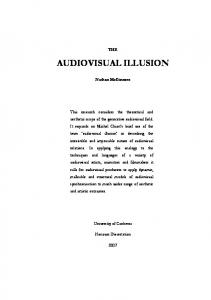
Motivation and Applications of the Parabola An important geometric characteristic of parabolas is that entering rays are reflected off the sides and redirected toward a common point— the focus. Receiving devices such as telescopes, some solar power plants [4], listening devices [5], and satellite dishes utilize this property to concentrate light, sound, and other signals. The inverse property—rays originating from the focus form a beam exiting the parabola—are used in transmission devices such as flashlights and headlights. Interestingly, the word focus originates from the Latin word for domestic hearth or fireplace [3]. Classroom Activity with the Mirage Illusion The Mirage Illusion by Opti-Gone International [2] uses two paired paraboloidal mirrors to create a 3-dimensional hologram of an object placed inside the apparatus. The object is placed at the bottom of the lower mirror, which by design coincides with the focus of the upper mirror. The image is displayed through an opening at the vertex of the upper mirror, which coincides with the focus of the lower mirror (see Figure 1). After a presentation on parabolas which includes their equations and a discussion of the geometric properties of the focus, students can be shown the Mirage Illusion and asked to discover how it works in
Figure 1. The Mirage Illusion device displaying a strawberry [2] small groups. Necessary materials include a ruler and a Mirage Illusion device for each group. Obviously, this is a fairly open-ended question and hence some suggestions of how to begin the investigation process might be required from the teacher. A central goal of the activity is for students to write an equation of the vertical cross-section of the mirror passing through the vertex (see Figure 2). From that equation they can calculate the location of the focus and verify that the focus of each mirror coincides with the vertex of the other. A derivation of an equation of Mirage Illusion cross-section might proceed as follows. Recall that a parabola with the y−axis as its axis of symmetry, having its focus at (0,p), and the line y = −p as its directrix (hence, having its focus at the origin) can be expressed by the following equation. 2
(1)
x =4py
This formula can be derived from the definition that a parabola consists of all points (x, y) which are equidistant from a fixed point (0,p) (the focus) and a fixed line y = −p (the directrix).
Figure 2. Cross-section view of the mirrors and example light rays [2]
Figure 3. Measurement of diameter at top of paraboloid
Expressing and equating these distances yields the equation
y p
x 2 (y p)2 ,
which simplifies to Equation (1). This may be a worthwhile algebra exercise.
Each paraboloidal mirror has a diameter of 9 inches and a depth of 1.5 inches [2]. The students approximate these dimensions by actually measuring the Mirage with a ruler.
Figure 4. Measurement of diameter at top of paraboloid
If we represent the cross-section as a parabola in the xy−plane, with vertex at the origin, and opening upward, then this data can be interpreted by saying that the parabola passes through the point (4.5, 1.5). Substituting this point into Equation 1 allows us to find the value of p. 2
2
x =4py ⇒ (4.5) =4p(1.5) ⇒ 20.25 = 6p ⇒ p = 3.375 This means that the focus of the lower mirror is 3.375 inches above its
vertex, which is consistent with the distance between the object and its image.
Figure 5. Measurement of depth of paraboloid using second ruler as a guide Parabolic Reflection Principle In this section we will use the physical fact that the angle of incidence is equal to the angle of reflection to prove that a ray entering a parabola parallel to its axis of symmetry will be reflected toward its focus. This is the principle fact explaining why/how the Mirage Illusion works. In Figure 6, Line I represents an incoming ray parallel to the y−axis, Q is the point of contact between that ray and the parabola given by x 2 4 py , Line T is the line tangent to the parabola passing through Q, and Point F is the focus of the parabola. Line R represents the path of the reflected ray and it is defined by the fact that it contains Q and is oriented such that m∠ DQE = m∠ BQC (since the angle of incidence equals the angle of reflection).
Proposition 1. Referring to Figure 6, Line R, which is defined as the line through Point Q with slope such that m∠ DQE = m∠ BQC, passes through Point F .
Figure 6.
Proof. Our approach to proving this will be to construct the equation of Line R and show that it is satisfied by the point (0, p). Begin by noting 2 that since Line T is tangent to the graph of x =4py at Q, we can compute its slope by using the derivative. From this we will find the measure of ∠ BQC.
y
x2 4p
y y |x
x 2p x0 2p
x0
m BQC tan
1
2p x0
Since m∠ DQE = m∠ BQC (angle of incidence equals the angle of reflection) and m∠ BQC = m∠ EQF (vertical angles), it follows that
2p x0
1
m∠ DQE + = m∠ EQF = 2 tan
Hence, the slope of Line R is
cot 2 tan
1
1 tan 2 (tan
2p x0
2 tan tan 2p x0
1
4 p / x0 x0 4p
p x0
2
1
1
2p x0 2p x0
Therefore, an equation for Line R is
y
x0 2 4p
x0 4p
p x0
x x0
which is easily seen to be satisfied by the point (0,p) (it might be worthwhile to have students verify this). Remark 1. If this proof were to be presented in a precalculus class, then the computation using the derivative in the above proof could be a replaced by a direct computation of slope using the difference quotient. Analogy with Ellipses Ideas entirely analogous to these can be presented in the context of ellipses. An ellipse is characterized by the geometric fact that a ray originating at one of its foci will be reflected by the ellipse toward the other focus. A proof of this fact is analogous to the proof of the proposition above. Although, the authors are unaware of a convenient classroom device analogous to the Mirage Illusion which illustrates or utilizes this property of ellipses, there are certainly many examples of real-life ellipse applications. One such example is the medical device called the lithotripter. Another fun application is an elliptical pool table. A classroom activity in the context of ellipses could be to ask students to draw their own ellipses using pegs (for the foci) and a string [1]. Justification for such a construction follows from the popular definition that an ellipse is the collection of all points in the xy−plane whose sum of distances to two fixed points is constant. The reflective property of ellipses will be visible during the construction by noting that m∠ AP F2 = m∠ BP F1 (see Figure 7).
Figure 7.
References [1] The Math Open Reference Project: http://www.mathopenref.com/constellipse1.html [2] Levin, Michael, Opti-Gone International: http://www.optigone.com/ [3] Online Etymology Dictionary: http://etymonline.com/index.php?term=focus [4] Solar Energy Generating Systems: http://www.nexteraenergyresources.com/ [5] Whisper Dishes on exhibit at the California Science Center: http://www.californiasciencecenter.org/Exhibits/CreativeWorld/Communication / Communication.php