commercial PC with a 2GHz Pentium IV processor for all the test matrices. Key Words: Reconfigurable architecture, SIMD/MIMD mixed-mode computing ...
Mixed-Mode Scheduling for Parallel LU Factorization of Sparse Matrices on the Reconfigurable HERA Computer Xiaofang Wang and Sotirios G. Ziavras Department of Electrical and Computer Engineering New Jersey Institute of Technology Newark, NJ 07102, USA {xw23, ziavras}@njit.edu ABSTRACT HERA (HEterogeneous Reconfigurable Architecture) is an FPGA-based mixed-mode reconfigurable computing system that we have designed and implemented for the simultaneous execution of a variety of parallel processing modes. These modes are SIMD (Single-Instruction, Multiple-Data), MIMD (Multiple-Instruction, MultipleData) and M-SIMD (Multiple-SIMD). Each processing element (PE) is centered on a single-precision IEEE 754 floating-point unit (FPU) and supports dynamic switching between SIMD and MIMD at runtime. Mixed-mode parallelism has the potential to best match the characteristics of subtasks in any application, thus resulting in sustained high performance. In this paper, we present our SIMD, MIMD and mixed-mode implementations on HERA of parallel LU factorization for sparse Block-Diagonal-Bordered (BDB) matrices. Experimental results with matrices of size up to 5000 x 5000 show that mixed-mode scheduling can improve the performance by up to 24.7% compared to the SIMD implementation and 22.2% compared to the MIMD implementation. We also show that HERA outperforms a commercial PC with a 2GHz Pentium IV processor for all the test matrices. Key Words: Reconfigurable architecture, SIMD/MIMD
mixed-mode computing, Floating-point arithmetic, Parallel LU factorization, Bock-Diagonal-Bordered matrices, Sparse matrices
1. Introduction SIMD and MIMD are the two fundamental modes in parallel processing. SIMD is attractive because it saves both hardware (uses only one control unit) and memory (only one copy of the program needs to be stored). Low PE-to-PE communication and synchronization overheads make it superior to MIMD in performing fine-grain algorithms [1-5]. Many numerical analysis algorithms, such as large-scale matrix multiplication and LU factorization, have a very high degree of structured, finegrain parallelism and can benefit substantially from the SIMD mode. SIMD’s superior ability for data parallelism _______________________________ *This work was supported in part by the U.S. Department of Energy under grant DE-FG02-03CH11171.
has created immense demand in such areas as weather analysis and gene study. From the implementation point of view, SIMD is also very efficient in silicon layout. However, SIMD machines are frequently under-utilized when programs are abundant in conditional instructions due to SIMD’s implicit synchronization. On the other hand, MIMD machines consist of independent PEs and are very good at conditional branching. However, numerous scientific and engineering problems, such as matrix operations and image processing, are primarily data parallel (i.e., SIMD) in nature and may perform poorly under MIMD. Recent years also have seen reevaluation of this SIMD vs. MIMD philosophy [4]. SIMD machines were very popular in the late 1980s and early 1990s [2, 4, 5]. With steady performance improvements in COTS microprocessors, MIMD machines have become more accessible than SIMD machines; because the latter are usually implemented with custom chips, and suffer from high cost and resilience to hardware upgrades. We all know from our experience with highperformance computing that the performance and efficiency of an algorithm highly depend on its good match with the target hardware. However, a typical application may have several subtasks that require different architectures. For a given machine configuration, the performance for most subtasks is not optimal because of the architecture's expected unsuitability. Mixed-mode heterogeneous computing, where the machine's operational mode (i.e., SIMD, MIMD, M-SIMD, etc.) changes dynamically as deemed suitable by the application, has proved to be a very effective approach in alleviating this problem and potentially getting the great performance by wishfully employing the most suitable architecture each time for the individual subtasks in the application [3]. Several prototype mixed-mode systems [3, 6-7] were implemented before the early 1990s by using COTS components. In these systems, the processors designated as the control units and the computing PEs were most often exclusively defined at static time and there was an interconnection network between these two groups. Thus, the role assignment of a processor either as a control unit or a PE was fixed at runtime. This can cause performance degradation due to inefficient utilization of the available resources. Also,
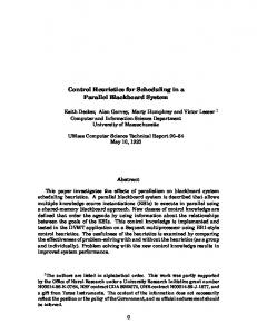
2. HERA Architecture Overview Figure 1 shows the general diagram of our HERA machine with m x n PEs interconnected via a 2-D mesh network. The 2-D mesh topology is ideal for our target
matrix-based applications and is also scalable. The computing fabric is controlled by the system Sequencer that communicates with the host processor via the PCI bus. Interrupt logic between the Sequencer and the host processor is implemented. The Global Control Unit (GCU) is included in the system Sequencer and fetches instructions from the global program memory (GPM) for PEs operating in SIMD. The total number of PEs is determined by the available resources in the target FPGA devices and the resource requirements of the application. The presence of FPGAs also makes it possible to dynamically adjust the capabilities of PEs at runtime to match the computation characteristics of the application. We employ fast, direct NEWS (North, East, West and South) connections for communications between nearest neighbors. Nearest PE pairs on the same row or column can also communicate through one port of the data memory of the PE to the west or north. Since every PE also has a Local Control Unit (LCU), the decoding of instructions is carried out by the LCU. By giving the decoding work to the LCUs, we avoid broadcasting a large number of control signals to all the PEs under SIMD mode. We still need global communication. Every column has a Cbus and all the Cbuses are connected to the Column Bus. M ain M em o ry
H o st Pro cesso r
PCI Bus
C b us _1
Seq u encer
C b us _2
GPM
C o lu m n B u s C bu s_ 3
C bu s_ n
D b u s1
P E (1 ,1 )
P E (1 ,2 )
P E (1 ,n )
D b u s1
D b u s2
P E (2 ,1 )
P E (2 ,2 )
P E (2 ,n )
D b us2
D bu sm
P E (m ,1 )
P E(m ,2 )
P E (m ,n)
D bu sm
Data Bus
GDM
Data Bus
these machines suffered from high communication overheads. Our HERA computer is dynamically reconfigurable and supports mixed-mode processing. It is based on new generation Xilinx platform FPGAs. FPGA-based reconfigurable computing is going through a revolution with the recent advent of multi-million gate devices. It is now viable to build programmable parallel systems that also support floating-point arithmetic on a single FPGA chip. It has been shown in [10] that the peak floatingpoint performance of FPGAs has outnumbered in the last 1-2 years that of modern microprocessors and is growing much faster than the latter. FPGA-based reconfigurable systems also introduce another dimension of flexibility; their runtime resource reconfiguration can further boost system performance. Every PE in HERA is built around an IEEE 754 single-precision FPU. It is equipped with its own control unit so that not only the whole system is dynamically partitionable, like previous mixed-mode systems, but also the role of each PE can be changed dynamically at runtime by using an HERA instruction. Thus, the system can be reconfigured dynamically at runtime to support a variety of independent or cooperating computing modes, such as SIMD, MIMD and M-SIMD, to best match in the time spectrum all subtask characteristics in a single application. The low communication overheads and very low cost of our approach add much needed promise to the highperformance, low-cost computing field. The LU factorization [8] of large sparse matrices is a computation greedy process and plays such an important role in many scientific applications that its efficient implementation has long been the focus of many research efforts. In [12] we present our results of parallel LU factorization for sparse matrices permuted into the BDB format; the target system was an in-house developed configurable, IP-based multiprocessor that was embedded into an Altera FPGA. In this paper, we propose SIMD, MIMD and mixed-mode scheduling schemes for BDBbased LU factorization on our new HERA system that comprises 36 PEs. The paper is organized as follows: In Section 2, an overview of the design and implementation of HERA is presented. Section 3 describes a parallel LU factorization algorithm for sparse BDB matrices. Its SIMD, MIMD and mixed mode mappings onto HERA are presented in Section 4. Experimental results and analysis are given in Section 5. In order to have a reference point to evaluate the computing power of the HERA computer, we also provide the performance of the sequential BDB LU algorithm on a commercial PC for the same matrices. Conclusions follow in Section 6.
We employed a RISC load-store architecture for our PE to save hardware resources. All data paths are 32 bits. The PE contains several major components: a 7-stage, pipelined, 32-bit IEEE 754 FPU, an LCU, 32-bit dualported local program memory (LPM), 32-bit dual-ported local data memory (LDM) and eight NEWS communication ports. The sizes of LPM and LDM were determined by the number of memory blocks in the FPGA device. The A port of LDM is accessed by the local PE, and the B port is shared with the neighbors to the south and east. A PE can directly write to or read from the
LDMs of its west and north neighbors via their B ports. This feature facilitates efficient large block data transfers and data I/O. Currently HERA implements about 30 instructions supporting floating-point arithmetic, branch and jump, memory access, inter-PE communication and system control. HERA supports both global and local PE masking. Every PE in the processor array is assigned an ID number and this number serves in global masking. The last seven bits of all the instructions select a particular PE or a group of PEs. Every PE holds a mask bit and computes the mask value with every instruction. A specific bit in instructions selects between global and local masking. The destination register of Get_N/E/W/S instructions or the source register of Send_N/E/W/S instructions can also be one of the four NEWS_OUT registers. In this innovative manner, data can bypass a PE to reach the next PE because we can use shared NEWS registers between PE pairs. Each PE comprises 32 32-bit general-purpose registers (GPRs) and several system registers: local instruction register (LIR), local program counter (LPC), data memory address register (DMAR), program memory address register (PMAR), local status register (LSR), 1-bit local mask register (LMR) and operating mode register (OMR). Similar to some other RISC processors, the R0 GPR is fixed at zero. The operating mode of each PE is set dynamically by the host processor through its OMR by using the Configure instruction: “0” indicates SIMD and “1” sets the PE into MIMD. All PEs operate in SIMD when powered up. To switch a PE to MIMD from SIMD, the sequencer first distributes the instructions to the LPM of the PE through the Column Bus and Cbus, and then sends a JumpI instruction to the PE with the starting address in the MIMD code. OMR is set to “1”. To switch back to SIMD, OMR is reset to “0” and the PE then listens for the broadcasting of a global instruction. The data in the registers and memories remain intact during switching. The instructions come from GPM in SIMD and from LPM in MIMD. The masking in the SIMD mode can use the PE’s ID number and/or LMR. Our first implementation was carried out on the highperformance WILDSTARII-PCI [11] FPGA board from Annapolis Microsystems. The board is populated with two tightly coupled Xilinx XC2V6000 Virtex II FPGA devices and 24MB of DDRII SRAM memory. 36 PEs fit into the two FPGAs. The board communicates with the host computer via the PCI bus interface. Every PE is assigned 4KB of LPM and 8KB of LDM. The interface to the PCI bus operates at 133MHz and the datapath is 64 bits. The computing fabric is clocked at 80MHz.
3. Parallel LU Factorization of BDB Matrices Due to the limited space in this paper, we just present an overview of the algorithm. Complete details can be found in [12]. LU factorization is a classic and widely employed direct method that solves a large system of simultaneous
linear equations presented in the form Ax = b; A is an N x N nonsingular matrix, x is a vector of N unknowns and b is a given vector of length N. It works as follows. We first factorize A so that A = LU, where L is a lower triangular matrix and U is an upper triangular matrix. Their elements can be determined by j −1 1 (1) and L ij = ( A ij − L ik * U kj ) * , for j ∈ [1, i − 1] k =1
U jj
i −1
L ik * U kj , for j ∈ [ i , N ]
U ij = A ij −
(2), respectively [8] if L
k =1
has 1’s on its diagonal. Once L and U are formed, the unknown vector x can be identified by forward reduction and backward substitution, respectively, using the two equations Ly = b and Ux = y. Since LU factorization is a computation-intensive procedure, its parallel solution has been a quite active research area. Thus, plenty of parallel techniques have appeared in the literature. Although the sequential LU factorization of sparse matrices appears easy to parallelize, it suffers from a significantly unique dynamic problem corresponding to the fill-ins (i.e., zero-elements that receive new values). Our earlier research [12] has revealed that it is often inefficient to extract instruction level parallelism (ILP) in the LU factorization of sparse matrices due to irregular data dependencies and the limited scalability of the parallel implementations. We believe that data partitioning is an efficient and scalable approach to parallelize LU factorization algorithms.
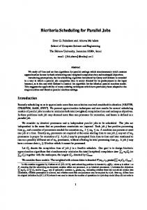
One of the partitioning schemes is to reorder and partition the A matrix into the BDB form by the nodetearing technique [9] or similar heuristics. In the BDB form shown in Figure 2, the Aik ’s represent matrix subblocks and all the non-zero elements in the matrix appear only inside these sub-blocks. For every fixed i, the blocks Aii, Ain and Ani are said to form a 3-block group, where i ∈ [1, n-1] and n ≤ N. Ann is known as the last block. The Aii’s will be referred to as the diagonal blocks, and Ain and Ani will be called right border block and bottom border block, respectively, where i ∈ [1, n]. The sizes of all the blocks after ordering are determined by the physical characteristics of the matrices and the ordering parameters, such as the maximum number of nodes in a block. For example, Figure 3 shows the nonzero patterns of a Jacobian matrix before and after ordering for the Newton’s power flow solution of a real 7917-bus power network. The Jacobian has dimension larger than the number of buses.
3. PAC: Parallel (global) accumulation of the partial results in all PEs in parallel after no more FAC or MAC tasks are left. This work can also be overlapped with FAC and MAC work. 4. LAST: Parallel LU factorization of the last block upon finishing all the factorization and multiplication work. The beginning of this work starts with the synchronization of the involved PEs. The last block is normally dense. (a) Original matrix %
&
'
(b) Ordered matrix ( '
!"#$ &
(
!"#$ )
)
Since all non-border, off-diagonal blocks contain only 0’s, if we apply equations (1) and (2) to a BDB matrix, we can find out that there will be no fill-ins in these blocks during factorization. Thus, the resulting matrix keeps the same BDB form, as shown in Eq. (3). L11 0 0 0 L 22 0 0 0 L33 0 0 0 Ln1 Ln 2 Ln 3
0 0 0 0 0 0 ... ... ... Lnn
U 11 0 0 0 U 22 0 0 0 U 33 0 0 0 0 0 0
0 0 0 ... ...
U 1n U 2n U 3n ... Unn
(3)
4. Mapping the Algorithm onto HERA The parallel LU factorization of sparse BDB matrices involves irregular computation patterns and blocks of various sizes as a result of the physical characteristics of the underlying problem. The higher the variance in block sizes is, the larger will be the resulting PE idle times under the SIMD mode of computation. However, many parts of the algorithm could still benefit from an SIMD implementation. As a natural sequence, a combination of appropriate parallel execution modes should give better results. Thus, we develop in this section three efficient scheduling approaches for this problem in order to investigate the performance of SIMD, MIMD and mixedmode implementations, respectively. For this application, our HERA machine comprises 36 PEs, which are configured in a 6 x 6 mesh layout
where 4.1 SIMD Implementation
Akk = LkkUkk −1 kk
Ukn = L Akn Lnk = AnkU kk−1 , for k ∈ [1, n − 1] n −1
LnnUnn = Ann −
LnkUkn k =1
The calculations of Lkk , U kk , Lnk and U kn for different k’s (i.e., 3-block groups) are independent. So we can distribute different 3-block groups to different processors in order to be factored in parallel with no data exchanges until the factorization of Ann. The last block, Ann, requires data produced in all the right and bottom border blocks, so its factorization is the last step. We can see that the sparse BDB matrix format presents great advantages for parallel implementation. In summary, the parallel BDB LU factorization includes the following jobs, 1. FAC: Independent factorization of all the 3-block groups. There is no data communication between PEs in this category of work. 2. MAC: Independent multiplication of the factored border block pairs ( LnkUkn ) and (local) accumulation of the partial products inside each PE to later produce the m −1 inner product LnkUkn , where mi is the total number of i
k =1
36
3-block groups assigned to PEi and
mi = n − 1 . Every i =1
resulting product has the same size as Ann. This work can be overlapped with the FAC work as long as the corresponding L and U blocks are already factored.
The factorization of all independent 3-block groups involves the same operations, so it is only natural to consider its implementation in the SIMD mode. Different PEs work on different 3-block groups, so there is no data communication until all 3-block groups have been processed. The PAC work is carried out in a logical binary tree and takes log p steps, where p is the number 2
of PEs (36 in HERA). The factorization of the last block is also carried out in SIMD and the data for the last block are scattered among the participating PEs. Depending on the size of the last block, it is possible that not all the PEs take part in the last factorization in an effort to reduce the communication overhead. The total execution time is m n −1 and Tsimd = T 1 ( FAC + MUL ) + log p T 2 + Tlast, where m = 2
i
i =1
36
n is the total number of independent diagonal blocks. T 1i ( FAC + MUL ) is the maximum execution time among the th
PEs for the i iteration. T 2 is the time to perform one addition and communication during the PAC work. T 2 may vary for operations between PEs that are not direct neighbors. We ignore this variance for simplicity. The shared memory port for three neighbors in HERA helps this procedure. The total number of iterations is m since this is the maximum number of 3-block groups that a PE receives. Tlast corresponds to the execution time for the last block.
Step 3
4.2 MIMD Implementation Sometimes there is large variance in the sizes of the 3block groups, especially for matrices in the real world (such as the electric power distribution networks). To minimize PE idle times, it may be more efficient to carry out the execution under MIMD in these cases. In this mode, all PEs work in MIMD at all times, including the factorization of the last block. Every PE fetches data and instructions from its own local memories (LDM and LPM). A PE is forced to be idle if there is no more task left, except the factorization of the last block. The PAC work may begin while some PEs are still working on FAC or MAC tasks. The worst case execution time is m where Tmimd = max { T 1 ( FAC + MAC )} + log p T 2 + Tlast , j
1≤ PEj ≤36
i
2
i =1 th
T 1i ( FAC + MAC ) is the execution time of the i iteration for
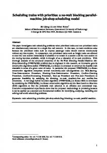
PEj that processes mj 3-block groups. 4.3 Mixed-Mode Implementation To map an application algorithm onto a mixed-mode system, the main focus is on identifying the optimal mode of parallelism for each subtask. We should also take into account the costs incurred when switching between different modes: SIMD/MIMD, SIMD/M-SIMD and MIMD/M-SIMD. The following is the general scheduling procedure to carry out parallel LU factorization of BDB matrices on our mixed-mode machine. Step 1 Identify 3-block groups of comparable size and put them into different task queues. Divide and (M-SIMD) configure the system into M-SIMD based on the task information. Assign 3-block groups from each queue to the PEs working in the same SIMD group, and perform the FAC and MAC work on these groups until the number of remaining 3-block groups is less than the number of PEs (i.e., 36). For example, suppose n=101 (i.e., 100 3-block groups) and the distribution of the sizes of the diagonal blocks is {50(80), 20(60), 15(40), 15(20)}, where 50(80) stands for 50 blocks of size close to 80 x 80. One possible PE mode configuration in this stage for this matrix is: (a) SIMD(36), for 36 groups with diagonal size 80 x 80; (b) SIMD1(14), for the remaining 14 80-blocks and SIMD2(20), for 20 60-blocks; (c) After the 20 60-blocks are finished, reconfigure SIMD2(20) to SIMD2(15), for 15 40-blocks and SIMD3(6), for 6 20-blocks. SIMD(x) denotes that x PEs are in this SIMD group. Step 2 Assign the remaining 3-block groups in such a (M-SIMD) way that groups of comparable size go to the same column of PEs (see Figure 1) and every PE has the largest possible number of idle nearest neighbors. This is an effort to facilitate the following PAC work. If necessary, reconfigure the system into a different M-SIMD layout.
(M-SIMD & MIMD )
Step 4 (M-SIMD & MIMD )
Step 5 (SIMD)
Step 6
A PE is reconfigured into MIMD as soon as it finishes its work and no more 3-block group is waiting in the task queue. Assign each PE in MIMD to the multiplication of a pair of (row and column) factored border blocks. Since the LDM has a shared port with its east and south neighbors, every idle PE will help its neighbors after it finishes its own work; no data transfer incurs in this process. After the factorization of all the 3-block groups and the multiplication of factored border blocks, reconfigure all the PEs again into the SIMD mode to carry out the PAC work. Factor the last block in the SIMD mode.
(SIMD)
Figure 4 shows a typical PE mode assignment in the above procedure for large BDB matrices. When the number of tasks in one or more task queues is larger than 36, we start with one or more single SIMD executions, which is a special case of M-SIMD in Step 1.
!
(*
)
(
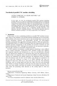
5. Performance Results and Analysis Experiments implementing the above three scheduling schemes were performed on the 36-PE HERA machine. Table 1 shows the characteristics of the test matrices and the execution times under these modes are presented in Figure 5. We also implemented the BDB LU factorization algorithm on a DELL Precision 8200 PC, which is equipped with an Intel Pentium IV 2GHz microprocessor and 256MB of memory. This processor was implemented using an 8-layer copper 0.13um process and the FPGA we are using was built with an 8-layer aluminum 0.15um process. It is obvious that mixed-mode parallelism consumes less time for all the matrices and the advantage increases as the size of the matrices increases. In the SIMD mode, some PEs are sometimes idle during the factorization of the 3-block groups and the multiplication of the border blocks. This results from the irregularity in the size and shape of the assigned 3-block groups. Due to insufficient work, for the 1000 x 1000 matrix the performances of the SIMD, MIMD and mixed modes are very close. In our architecture, the communication cost is
not significant higher than that of SIMD, so their performance is also close. However, MIMD tends to perform better than SIMD in this algorithm for large matrices. HERA outperforms the PC under all the execution modes and actually its execution time increases at a lower rate than that for the PC. &( + Matrix size (N) 1000 Total diagonal 31 blocks (n) Dimension of 33 the largest diagonal block Dimension of 19 the smallest diagonal block Dimension of 35 the last diagonal block
2000 71
3000 89
4000 117
5000 145
51
57
80
129
38
21
25
33
80
121
153
224
reflected in the experimental results which demonstrate higher performance with increases in the matrix size. Mixed mode is the best choice for all the matrices in this problem. MIMD tends to outperform SIMD for large matrices. We will continue to include additional features in our architecture and explore more mapping techniques for matrix-based problems. The benefits of mixed-mode execution should become more visible with applications that have more irregular computation and communication patterns, and involve more frequent conditional executions. With the anticipated speed and density improvements for FPGAs, the high performance and costeffectiveness of our approach will become even more preeminent in the near future.
References [1]
350
[2]
SIMD MIMD
300
MIXED-MODE
Execution time (ms)
DELL PC
250
[3]
200
150
[4]
100
50
[5]
0 1000 x 1000 2000 x 2000 3000 x 3000 4000 x 4000 5000 x 5000
Matrix size
HERA system frequency: 80MHz
" ) ) 00 *+
.
) ) /
,- . -,-
[6] )
(
6. Conclusions
[7] [8]
Mixed-mode parallelism can match better the requirements of application algorithms throughout execution. Thus, it can deliver much better performance than the pure SIMD and MIMD execution modes. Recent significant advances in new generation FPGAs provide a viable and cost-effective approach in building highperformance parallel computing platforms that target scientific computing. We have presented here SIMD, MIMD and mixed-mode implementations of parallel LU factorization for large sparse BDB matrices on our 36-PE HERA machine. HERA is a reconfigurable, pipelined computing engine embedded in platform FPGAs. It is flexible enough to allow mixed-mode execution realizing various parallel processing modes such as SIMD, MIMD and M-SIMD. Our design also supports floating-point operations. The advantage of mixed-mode parallelism is
[9]
[10]
[11] [12]
M. D. Theys, T. D. Braun and H. J. Siegel, "Widespread Acceptance of General-Purpose, Large-Scale Parallel Machines: Fact, Future, or Fantasy?" IEEE Concur., Vol. 6 No. 1, January-March 1998, pp. 79-83. B. Parhami, “SIMD Machines: Do They Have a Significant Future?” Report on a Panel Discussion, 5th Symposium Frontiers Massively Parallel Computation, McLean, LA, Feb. 1995. H.J. Siegel, M. Maheswaran, D.W. Watson, J. K. Antonio and M. J. Atallah, “Mixed-Mode System Heterogeneous Computing,” in Heterogeneous Computing, M. M. Eshaghian (Ed.), Artech House, Norwood, MA, 1996, pp. 19-65. W.C. Meilander, J.W. Baker and M. Jin, “Importance of SIMD Computation Reconsidered,” Proc. 17th IEEE Int'l Parallel Distributed Processing Symp. (IPDPS2003), April 2003, pp. 266–273. J.D. Allen and D.E. Schimmel, “Issues in the Design of High Performance SIMD Architectures,” IEEE Transactions Parallel Distributed Systems, Vol. 7, Issue 8, Aug. 1996, pp. 818–829. H.J. Siegel, et al., “The Design and Prototyping of the PASM Reconfigurable Parallel Processing System,” Parallel Computing: Paradigms and Applications, International Thomson Computer Press, London, 1996, pp. 78-114. G. J. Lipovski and M. Malek. Parallel Computing: Theory and Comparisons. Wiley, New York, 1987. I. S. Duff, A. M. Erisman and J. K. Reid, Direct Methods for Sparse Matrices, Oxford Univ. Press, Oxford, England, 1990. A. Sangiovanni-Vincentelli, L. K. Chen and L. O. Chua, “Node-Tearing Nodal Analysis,” Tech. Report ERLM582, Electronics Research Laboratory, College of Engineering, University of California, Berkeley, Oct. 1976. K. Underwood, “FPGAs vs. CPUs: Trends in Peak Floating-Point Performance,” ACM/SIGDA 12th International Symposium on Field Programmable Gate Arrays, Monterey, CA, Feb. 2004, 171-180. http://www.annapmicro.com/. X. Wang and S.G. Ziavras, "Parallel LU Factorization of Sparse Matrices on FPGA-Based Configurable Computing Engines," Concurrency Computation: Practice Experience, Vol. 16, No. 4, April 2004, pp. 319-343.