Mobility Anchor Point Selection Based on User Mobility in HMIPv6 Integrated with Fast Handover Mechanism E. Natalizio, A. Scicchitano and S. Marano DEIS, Via Pietro Bucci, Cubo 42/c, 87036, Arcavacata di Rende, University of Calabria
[email protected],
[email protected],
[email protected] Abstract – In the context of Hierarchical Mobile IPv6 integrated with Fast Handover mechanism, this paper proposes two MAP selection algorithms, both based on the classification of users depending on their mobility. Furthermore an enhancement of one of the two algorithms is presented, it introduces the concept of bufferization at MAP level. Extensive simulations have been performed to analyse and investigate algorithms results.
Keywords – hierarchical mobile, fast handover, micromobility protocols I. INTRODUCTION Recently the international community of researchers has put a lot of efforts in studying and analysing telecommunications protocols able to guarantee network connections to mobile users. The main goals of this kind of protocols are: maintain active users’ sessions nevertheless possible changes in the point of attachment and provide them with a satisfactory Quality of Service while on the move. Some years ago the Internet Engineering Task Force (IETF) presented a pioneering solution: Mobile IP, first for IPv4 [1] then for the new Internet Protocol version, IPv6 [2]. These protocols are able to deliver IP packets during user roaming, they introduce new network elements: the Home Agent (HA) and the Foreign Agent (FA), which work as proxy agent of the Mobile Node (MN) in its Home Network (HN) and in the Foreing Network (FN), respectively. Both MIPv4 and MIPv6 solve the mobility problem in a general manner, but they open several other particular issues, descending from an unique question: “what does it happen in MIP during and after an handover?” An handover, between different access points, in MIP, means the change of CoA (the address assigned to the MN in the FN). This change of address forces the MN to notify the HA, and in MIPv6 with route optimization also the CNs, introducing unacceptable delays in packets delivering and QoS degradation. To face this problem it became necessary to split the mobility domain in: macromobility and micromobility. Micromobility is referred to the movements a user performs within one administrative domain, while macromobility is moving through more than one administrave domain.
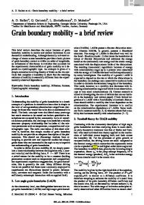
Several micromobility protocols have been proposed in literature [3-7], in order to solve the problem of users’ mobility in a limited geographical area. Only two are still on the stage: Hierarchical Mobile IPv6 [8] and Fast Handover for Mobile IP [9]. The former introduces a hierarchical structure of Foreign Agents, called Mobility Anchor Points (MAPs), which cares about users mobility within a network domain. The latter is not properly a micromobility protocol, but a mechanism, involving layers 2 and 3, able to maintain the requested Quality of Service in spite of the handover due to the change in the point of attachment. Fast handover schemes have been proposed for different IP wireless networks [10], they have been analysed with Mobile IP [11], extended for working with IEEE 802.11 [12], and with HMIP both in the macromobility [13] and in the micromobility contexts [14]. This work starts, in section 2, with introduction of Hierarchical Mobile IPv6 and Fast Handover for Mobile IPv6 alone and together; the simulated scenario is presented in section 3; section 4 and 5 report the proposals of algorithms and their performance, respectively, then section 6 includes conclusive remarks. II. HMIPv6 AND FAST HANDOVER A new entity, namely MAP (Mobility Anchor Point), has been introduced in Hierarchical Mobile IPv6. The MAP can be located at any level of a hierarchical network of routers, as illustrated in Fig.1. In HMIPv6 a MN is assigned two care-of addresses (CoA), instead of one as in MIPv6. The addresses are called Regional Care-of-Address (RCoA) and On-Link Care-of-Address (LCoA). The MN obtains the RCoA from the MAP in the visited network, and it is an address on the MAP’s subnet. The LCoA is the same as the CoA in MIPv6; i.e., it is based on the prefix advertised by the AR, and changes any time the MN changes its current AR. When a mobile enters a new MAP domain, it receives Router Advertisements (RA) from the ARs, this message contains information on MAPs availability, distance from the MN and priority. After selecting a MAP, the MN gets the RCoA on that
MAP’s domain and its LCoA from the current AR. Then it sends a Binding Update (BU), containing both RCoA and LCoA, to the MAP, in order to create the binding between the
Hierarchy of MAPs
A
1
B
2
5
4
6
Access Routers 880 m
3
C 880 m
Fig.1. Hierarchy of MAPs (A: AR coverage area, radium=170m; B: overlapping area between ARs, 30m; C: distance between the streets, 170m).
two addresses. The MAP stores the binding in the Binding Cache (BC) and forward the BU to the mobile’s HA and Correspondent Nodes (CN), in order to make them aware of the new mobile’s RCoA. Basically the MAP behaves as an HA: when CNs send messages to the MN’s RCoA, they are received by the MAP, which in turn tunnels the messages to the MN’s LCoA using IPv6 encapsulation. However, the MN is always able to send data directly to all CNs. As far as a mobile moves through different ARs in the same MAP domain, it does not need to inform the Home Agent (HA) about its movement, because the RCoA remains unchanged and only the LCoA has to be modified. If it moves outside the MAP domain, also the HA and the CNs have to be informed of the change. When MN sends a BU to the CNs that are situated within the site, these CNs are able to send data packets directly to the MN without MAP intervention. Fast Handover for Mobile IPv6 has been one of the several extensions proposed in literature in order to prevent the quality of service degradation, caused by the change in the MN point of attachment. When a MN gets aware of its movement, by link layer trigger or by new point of attachment RA, it is allowed to send a Router Solicitation for Proxy Advertisement (RtSolPr) to the previous AR (PAR) with the information [AP-ID, AR-Info] it got by the new AR (NAR). On receiving this information the
PAR sends to the MN a Proxy Router Advertisement (PrRtAdv), containing the proposed new CoA (NCoA). When the MN receives confirmation of a pending Layer 3 handover, it sends a Fast Binding Update (FBU) to the PAR, asking for using the NCoA. The MN could use this address immediately after attaching to the new subnet link, when it has received Fast Binding Acknowledgment (FBack) prior to its movement. In the case the MN moves without receiving a FBack, the MN can start using NCoA after announcing its attachment through a Fast Neighbor Advertisement (FNA). With this mechanism, a MN can send and receive packets from the time it disconnects from one point of attachment to the time it connects with a new point of attachment in a new subnet, using a tunnel established between PAR and NAR and without experiencing unacceptable interruptions for real time services, such as voice over IP. More details about this protocol are in [9]. Starting from reference [14], this work takes in consideration a possible integration, called F-HMIPv6 of HMIPv6 and Fast Handover. HMIPv6 remains the protocol used to solve the micromobility problem within the entire site whilst FH, opportunely adapted, focuses on the change between two ARs, belonging to the same MAP domain, fig. 2.
CN
HA
Internet
MAP RCoA
PAR
PLCoA
NLCoA
NAR
MN
Fig.2. F-HMIPv6 integrated architecture.
When a MN enters a new MAP domain, it starts the registration procedure with the CNs and the HA in the classical HMIPv6 manner. If it needs to change only the AR, without exiting from the old MAP domain, it will perform a FH
procedure. In F-HMIPv6, the PAR is replaced in its functionalities by the serving MAP, so that, during a fast handover, a tunnel between the serving MAP and the NAR, rather than between PAR and NAR, is established. This tunnel decreases the delay in the delivering due to the unnecessary passage through the PAR. Upon the completion of the registration the MAP-NAR tunnel is dismissed and the packets are forwarded by the NAR to the MN. This integration introduces two kinds of LCoA: the Previous Local Care-ofAddress (PLCoA) located at the PAR and the New Local Careof-Address (NLCoA) located at the NAR (fig.2). The procedure described could be accomplished by minor changes in HMIPv6 as described in [14]. In next section, the scenario where HMIPv6 and FH act together is presented. III. SIMULATED SCENARIO The simulated scenario consists of a four levels binary-tree hierarchy, containing 15 MAPs. Twenty-five ARs are present in the lower (the fifth) level of the hierarchy, distributed in a non-uniform manner (as in fig.1). Each AR covers a circular area of 170 meters of radium and can manage up to 10 users. An overlapping region of 30 meters exists between each couple of ARs. A MN is provided with an HA and a CN, both far from the foreign domain. The MN communicates with these nodes during its whole sojourn time within the site. This scenario is integrated with a mobility simulator. Its main entities are the pedestrian users, able to walk with a velocity randomly chosen in the range 0.5÷4 m/s (correspondingly to 1.8÷14.4 km/h, slow walk and marathon pace, respectively). They can move in a planar grid of 880m x 880m, composed of five horizontal and five vertical streets, far 170m each other. The mobility scenario represents a city centre Manhattan-like, where no vehicles are allowed. The mobile users can only walk along the streets, in both the directions; when they arrive at a cross, they can choose whether turn (on left or right) or keep the path along they are moving. All the results are drawn after statistical averaging on ten sample of simulations, lasting 40000s each. The number of users varies from 50 up to 170, with a step of 30 units. In accord with the users velocity range chosen for the pedestrians (0.5÷4 m/s), four velocity thresholds, specified in Table I, for the -UP algorithms have been considered, one for each level in the MAP hierarchy: TABLE I VELOCITY THRESHOLDS FOR FHMIP-UP AND HMIP-UP Velocities Intervals (m/s) 0.5