basic auto-repair. .... modules and automatic tools for communication code .... location information. Reusable general purpose knowledge base. IED Class.
Proceedings of the 2005 Knowledge Intensive Multi-Agent Systems (KIMAS) Conference, Waltham, MA, April 18-21, 2005.
Mobility Open Architecture Simulation and Tools Environment Stephen Balakirsky, Chris Scrapper, Elena Messina National Institute of Standards and Technology, Gaithersburg, MD Email: {stephen.balakirsky, chris.scrapper, elena.messina}@nist.gov Abstract – This paper will describe the Mobility Open Architecture Tools and Simulation (MOAST) environment. This environment conforms to the NIST 4D/RCS architecture [3] and allows simulated and real architectural components to function seamlessly in the same system. This permits not only the development of individual components, but also allows for component performance metrics to be developed and for the components to be evaluated under repeatable conditions. The environment is composed of high-fidelity and low-fidelity simulation systems, a detailed model of real-world terrain, actual hardware components, a central knowledge repository, and architectural glue to tie all of the components together. This paper will describe the components in detail and provide an example of how the environment can be utilized to develop and evaluate a single architectural component through the use of repeatable trials and experimentation that includes both virtual and real components functioning together.
1. INTRODUCTION The development of an embodied multi-agent system is truly a multi-disciplinary endeavor. It requires skills and expertise in fields as varied as sensor processing, knowledge representation, planning, execution and control, and even basic auto-repair. In addition, the “multi” in multi-agent implies that there are multiple platforms that may require multiple safety personnel and a large amount of real estate to perform over. A lighthearted, but realistic view of the development cycle may be summarized by: 1. Develop a cool new algorithm for accomplishing task ‘x’. 2. Code an implementation of algorithm ‘x’. 3. Get code to compile for real vehicle(s). 4. Assemble team to test algorithm on real vehicle(s). 5. Immediately discover implementation bug, hardware failure, or software change to supporting subsystem, dismiss team and recode algorithm or fix vehicle(s). 6. Reassemble team and search in vain for exact same scenario that caused crash (literally or figuratively) in 5. 7. Repeat from 3. As seen from the above summary, much of the development cycle is out of the control of the algorithm developer. Vehicle up-time, safety personnel availability, and course availability play a large role in the development schedule. In
addition, it may be difficult to isolate failures due to a lack of repeatable trials and the use of software modules that are being co-developed (which module has the bug?). The need to develop on real hardware may severely limit the ability of expertise or resource constrained institutions to fully participate in the field. In addition, research in a particular discipline may be constrained by the current stateof-the-art in unrelated disciplines. For example, when operating on a real system, the planning community can only construct plans based on features that the sensor processing community is able to detect. It is difficult or impossible to answer the question of how the system’s plans would be affected if it could see feature ‘x’ at range ‘y’. Because of this, planning researchers are unable to explore behaviors that require next generation sensor processing until after that generation has arrived. Traditionally, many of these problems have been addressed by using a simulation environment for algorithm development and testing. Simulation has benefits that include reduced competition for scarce resources, no risk of harm to personnel or equipment, the ability to add as yet undeveloped capabilities to subsystems, and the ability to perform repeated tests over vast and varied terrains from the comfort of your own desk. As a result, an individual code module can be thoroughly tested and understood before moving to real hardware. Numerous simulators have been developed over the years to assist in the development, testing, and evaluation of autonomous vehicles. These simulators have provided a cost effective solution to the development of autonomous vehicles by alleviating the cost of maintaining an actual vehicle, test course, and safety facilities in which to experiment with the systems. Most simulators developed in the past are dedicated to testing entire autonomous systems under a specific task in a static environment, or a single subsystem of the autonomous system under varied conditions [1,10]. Simulated Highways for Intelligent Vehicle Algorithms (SHIVA) [15], for instance, provided realistic sensor models, communication infrastructure, and a variety of driver models that allowed for the testing of tactical decision-making in a mixed traffic environment. SHIVA was designed to allow for migration of the subsystems being tested in the simulation environment to the actual vehicle platforms. The View Simulation System (VSS) [10] provides high performance graphic facilities to test vision-based autonomous systems. While both of these systems provide high-fidelity testing of
certain components, neither provides realistic mobility models or computation facilities to adequately simulate complexities that exist in real world environments. One Semi-Automated Forces (ONESAF) [11] expanded the realm of simulation environments by providing an open, modular architecture that simulates vehicle behaviors, sensors, and weapon systems in a larger multi-agent environment. ONESAF sacrifices fidelity in order to divert its computational facilities to controlling multiple entities autonomously in the environment. Due to the inherent nature of such a simulation package, ONESAF availability is limited to U.S. government distribution. Recently, simulation environments have attempted to leverage existing technologies to achieve a general-purpose environment that is capable of simulating the complexities of multi-agent, feature rich environments. Gamebots [8] is a multi-agent test-bed for AI that was built on the Karma game engine of the popular video game Unreal Tournament. The system provides a client-server architecture that allows “bots” and humans to interact. Gamebots uses built-in scripting languages and 3D modeling faculties to allow a developer to create or modify the simulated environment. USARSim [16], which in turn was built on Gamebots, makes effective use of the rich kinematics models that exist in the Karma game engine to simulate Urban Search and Rescue environments. USARSim and others have extended the Gamebots API to provide virtual sensors, decisionmaking facilities, and worlds that accompany the simulation environment. As more agents are simulated in larger and more complex worlds, the computational complexity of the simulation grows. Distributed Virtual Simulation Environments (DVSE) [5] have been developed to manage this computational complexity. UTSAF [9,12] is a simulation bridge between the Unreal game engine and ONESAF. This bridge parses the standardized Distributed Interactive Protocol (DIS) used by ONESAF to facilitate the communication and participation of both simulators in a single hierarchical distributed virtual simulation environment. This hierarchical distributed model provides a high fidelity simulation environment that precisely simulates entities in a specified sphere of influence, while a low-fidelity simulator simulates a larger region. Player/Stage [7] is another example of a hierarchical distributed virtual simulation environment that was developed as a package and does not require the use of a separate bridge for the integration of both the high- and lowfidelity simulators. A typical development cycle with the use of a simulator may be represented by: 1. Develop cool new algorithm for accomplishing task ‘x’. 2. Code an implementation of algorithm ‘x’. 3. Get the code to compile for simulation engine. 4. Test/debug code in simulated environment.
5. 6. 7. 8.
Recode implementation to work with real robot(s). Assemble team to test code on robot(s). Find that simulated world does not accurately represent real world and that algorithm redevelopment is necessary. Go to “Classic” Development and Test Cycle.
As shown above, there is still no replacement for testing the algorithms on the real hardware. The reason for this is that simulation environments are typically composed of worlds that do not include false alarms or missed detections, have perfect command execution, and ideal system performance. The result of this is that an algorithm that works perfectly in simulation is not guaranteed to work at all under actual environmental conditions, platform performance, and command execution. Therefore, step 5 in the development cycle calls for the simulated algorithm to be ported and run on the actual robot hardware. The problem with this is that differences in interfaces or knowledge requirements often prevent plug-and-play operation of an architectural component from the simulation environment to the real hardware. For many simulation-system/real-hardware combinations, substantial code and command interface changes must be made. These changes may introduce new bugs and may also lead to the discovery that algorithms have become dependent on unrealistic or non-existent attributes from the simulation environment. The next evolutionary step in the distributed simulation models is to incorporate real hardware in virtual environments. Player/Stage and RAVE [6] are two simulation environments that provide numerous controllers for a variety of vehicle platforms. The real virtual simulation environments permit seamless integration and transparent transference of data between the real and simulated components. This allows for developers to take advantage of the real mobility characteristics of vehicle platforms while still providing a controlled environment. At the National Institute of Standards and Technology (NIST), the Mobility Open Architecture Simulation and Tools (MOAST) environment has been developed as a real/virtual environment that allows researchers to concentrate their efforts in their particular area of expertise. This environment conforms to the NIST Real-Time Control System (RCS) architecture [3] and allows simulated and real architectural components to function seamlessly in the same system. This permits not only the development of individual components, but also allows for component performance metrics to be developed and for the components to be evaluated under repeatable conditions. The environment is composed of high-fidelity and low-fidelity simulation systems, actual components under test, a detailed model of real-world terrain, a central knowledge repository, and architectural glue to tie all of the components together. This paper will describe the components in detail and provide an example of how the environment can be utilized to develop and evaluate a single architectural component through the
use of repeatable trials and experimentation that includes both virtual and real components functioning together.
2. THE MOAST ENVIRONMENT The MOAST environment strives to seamlessly integrate simulation subsystems with real robotic hardware subsystems. The goal is to allow the individual subsystems to each perform in the area where and when they do best. For example, simulation systems can replicate multiple platforms for the development of multi-platform behaviors. They allow for repeatable events, and may provide detailed system/event logging. In addition, by simulating the results of sensor processing, the potential benefits of detecting new features or utilizing novel sensing paradigms may be measured. However, there is no substitute for real mobility, sensing, and communications. Therefore, when available, real system components/subsystems must be able to plug into the MOAST environment and replace simulated subsystems. This is made possible through the architectural glue of the environment. This glue includes a reference model architecture that includes well defined interfaces and communications protocols, and detailed specifications on individual subsystem input/output (IO). The Real-Time Control System (RCS) reference model architecture has been selected for the MOAST reference model architecture. All communications between modules is accomplished over Neutral Messaging Language (NML) channels [14] that function as the communication medium. Architectural Glue In order to guarantee real-time operation and decompose the robotic system into manageable pieces, it was necessary to utilize a hierarchical architecture that was specifically designed to accommodate real-time deliberative systems. The RCS reference model architecture is a hierarchical, distributed, real-time control system architecture that meets this need while providing clear interfaces and roles for a variety of functional elements [2,3]. a SENSORY OUTPUT
STATUS
UPDATE
SENSORY PROCESSING
PREDICTED INPUT OBSERVED INPUT
SENSORY INPUT
VALUE JUDGMENT SITUATION EVALUATION
PERCEIVED OBJECTS & EVENTS
PLAN RESULTS
RCS Node PEER INPUT OUTPUT
COMMANDED TASK (GOAL)
EV PL A L AN UA TI O
PLAN
WORLD MODELING
OPERATOR INTERFACE N
BEHAVIOR GENERATION
STATE
KNOWLEDGE DATABASE To Higher and Lower Level World Modeling STATUS
COMMANDED ACTIONS (SUBGOALS)
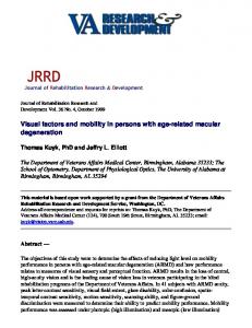
Figure 1. Internal structure of a RCS_NODE (from [3] p. 28).
Through RCS, a clear system hierarchy exists that provides control ranging from that of individual actuators up to groups of 10s or 100s of platforms. Each level of the
hierarchy is composed of the same basic building blocks illustrated in Fig. 1. These building blocks include behavior generation (task decomposition and control), sensory processing (filtering, detection, recognition, grouping), world modeling (knowledge storage, retrieval, and prediction), and value judgment (cost/benefit computation, goal priority). While the architecture specifies the general content and frequency of communications, it does not provide details on the actual message format. The NML toolkit is utilized to fill in this information. The NML toolkit provides general templates for command and status messages that are transmitted between RCS modules and automatic tools for communication code generation based on these templates. As the MOAST environment is implemented for different domains, these templates must be flushed out and completed for every module in the system. As will be discussed later in this paper, the MOAST environment has been implemented for on- and off-road robotic vehicles and detailed specifications exist for all of the vehicle environment communication channels. During actual operation, JAVA1 based tools are provided that allow for automatically generated status windows that provide a complete picture of the communications hierarchy as well as the content of every command and status message that is flowing through the system. Central Knowledge Repository The reference model architecture must provide for a means of coordination amongst peers as well as command and control of subordinates in order to provide coherent multiagent behaviors. While it is feasible that coordination may be accomplished through the use of status channels, the MOAST environment provides a central knowledge repository as an additional means of coordination. This knowledge repository is based on domain specific schemas that are implemented through the use of a central SQL server. In addition to schemas, the knowledge repository contains policies that uniquely specify which module is authorized to populate each knowledge field. The populated schemas constitute a knowledge base that contains information ranging from a priori environmental data and module capabilities data to real-time state and status information. A complete knowledge base for a specific multi-agent ground robot system has been developed and will be discussed in later sections. Detailed Terrain Model A priori environmental data contained in the central knowledge repository is derived from a detailed terrain model contained in the MOAST environment. This model may be decomposed into a portion that is known a priori 1
Certain commercial software and tools are identified in this paper in order to explain our research. Such identification does not imply recommendation or endorsement by the National Institute of Standards and Technology, nor does it imply that the software tools identified are necessarily the best available for the purpose.
and a portion that will be discovered through normal agent operation. A priori information may be preprocessed and populated into the central knowledge repository where it is available to all subsystems. Discoverable knowledge is operated on by simulated sensors and appears as the results of sensor processing that may be reported thorough NML status channels or through a central knowledge repository knowledge base. Actual Components The central theme of the MOAST environment is the ability to test actual individual hardware/software modules. The only requirement for operating under the MOAST environment is conformance to the MOAST communications protocols and formats. The NML communications libraries are freely available from NIST in source format as well as precompiled for numerous operating systems2. Since all modules conform to the same communications protocols and formats, the module under test will be unaware of which participating modules are real and which are simulated.
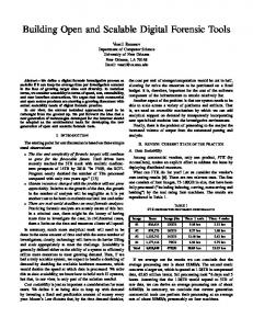
Figure 2: MOAST implementation including simulated (light) and virtual (dark) components. 2
See http://www.isd.mel.nist.gov/projects/rcslib/
Simulation Systems As with actual components, the only requirement on simulation systems is conformance to the MOAST communications protocols and formats. Currently, simulation systems have been used to simulate the results of sensor processing and platform mobility. By simulating sensor processing results, experiments may be performed that utilize repeatable events from as yet unrealized sensor capabilities, or results from sensors that may be too expensive, large (weight, volume, or power), or delicate to place on mobile platforms. Simulated mobility allows varied repeatable terrain and the inclusion of multiple non-existent platforms.
3. IMPROVISED EXPLOSIVE DEVICE IMPLEMENTATION Under funding from the Army Research Laboratory (ARL), C. Shoemaker program manager, the MOAST environment has been implemented to develop the behaviors that a platoon of robotic vehicles capable of neutralizing an improvised explosive device (IED) would need to perform. In performing this mission, a group of robotic agents must identify and neutralize an IED, otherwise known as a roadside bomb. A conventional solution (implementation solely on real hardware) is not possible due to the fact that there is no known sensor for detecting/neutralizing an IED and that it would be too dangerous to intentionally place bombs on roadways around our research facility. A block diagram of the implemented system is shown in Fig. 2. In the diagram, the light boxes are simulated components and the dark boxes are real systems. The system is composed of three vehicles; all of which have simulated sensing and lowlevel mobility. Architectural Glue One of the first jobs for the system designer is to determine the module interfaces. Whenever possible, it is desirable to reuse existing interfaces since this allows for the reuse of entire code modules. In the case of the IED mission, many of the mobility system behaviors are identical to previously designed road driving systems that have been constructed under the MOAST environment [4]. In fact, the entire subsystem echelon mobility code was used without modification. As one moves higher in the hierarchy, skills and behaviors become more specialized for the individual mission and new behaviors must be added to augment already existing skills. For example, the existing vehicle echelon mobility planner was able to plan to drive along a section of roadway, however no behavior had yet been created for cautiously driving around a suspected IED. The existing interface specification must be updated and the corresponding controllers augmented with this new behavior. A graceful failure mode of controllers not compliant with the new specification is still possible through the report of an “unknown command” over the systems status channel and error log.
Central Knowledge Repository As with the module interfaces, the MOAST environment allows for the reuse of knowledge components that have been previously developed for other applications. Table 1 depicts the knowledge bases contained in the knowledge repository and their origin.
information about objects, the knowledge repository is useful as a means of coordination and synchronization amongst peers. For example, the vehicle echelon mission executor utilizes the vehicle status knowledge base to synchronize sensing mode changes with changes in mobility modes.
Table 1: Knowledge bases that form the central knowledge repository.
Detailed Terrain Model A detailed terrain model has been generated of the NIST campus. This terrain model consists of a bare earth elevation array with post spacing of 45 cm (1.5 feet) and root mean square error (RMSE) of 15 cm (6 inches), color orthophotography with pixel resolution of 7.5 cm (0.25 feet), and comprehensive vector data. The vector data includes items such as all road edges, parking lots, parking lot strips, buildings, sidewalks, lamp posts, signs, etc.
Knowledge base Road Network Database
Vehicle Characteristics
Vehicle Sensor Characteristics Vehicle Weapon Characteristics Vehicle Status
IED Class Characteristics
Vehicle Team Composition
IED Instance Characteristics Error Log
Purpose Contains a hierarchical decomposition of road networks from constant curvature lane segments to complete roadways. Contains average values for common types of vehicles and vehicle class relationships. Contains average values for sensor ranges, fields of view, etc. Contains weapon lethality, range, etc. Contains mode, health, and location information. Contains expected blast radius, safe approach radius, etc for various types of IEDs. Requirements on sensing and mobility to fill different roles in mission (Leader, observer, …). Specifics about potential IEDs (class, location, status, … ) Provides global logging of error conditions.
Origin Reusable general purpose knowledge base originally developed for on-road driving under DARPA MARS project, PM Doug Gage [13]. Reusable general purpose knowledge base. Reusable general purpose knowledge base. Reusable general purpose knowledge base. Reusable general purpose knowledge base. Developed for IED mission.
Reusable general purpose knowledge base extended for IED mission. Developed for IED mission. Reusable general purpose knowledge base.
As is shown in the table, the majority of the knowledge bases are general purpose and may be used for multiple domains. In addition to storing a priori and dynamic
Incorporating a high-fidelity terrain model into the MOAST environment allows for algorithm performance evaluation and the ability for mobility planning systems to incorporate items that are not yet detectable by current state-of-the-art sensor processing algorithms. For example, as the vehicle drives through the real world, detected road edges may be compared with those in the terrain model to measure the performance of the road detection algorithms. For the case of the IED mission, it is desirable to have simulated sensor processing coupled to real mobility. This allows the highlevel behaviors to function even though there are currently no sensor processing algorithms capable of distinguishing classes of IEDs. Actual Components As shown in Fig. 2, the majority of the system elements above the subsystem echelon were real components running on actual system hardware. Through the use of the MOAST global world model and interface specifications, module functionality is identical to a completely implemented robotic platform. Simulated Components For this particular implementation of the MOAST environment, virtual sensing was provided through interfaces and behaviors added to the OTBSAF simulator. This simulation system provided IED behaviors (they explode if approached before disarming, techniques for disarming, etc.), sensor output that included terrain and entity features for multiple classes of sensors, and a visualization of the mission as it progressed. Low level mobility simulation was performed by an internally developed simulation system. In the near future, we will be interfacing to a commercial simulation package that will provide physics based simulation of vehicle motion.
4. SUMMARY AND FUTURE WORK This paper has presented a novel approach to system development. Under this approach, a new development cycle may be coined as follows: 1. Develop cool new algorithm for accomplishing task ‘x’. 2. Code an implementation of algorithm ‘x’. 3. Get code to compile for simulation engine. 4. Test/debug code in simulated environment. 5. Run identical code on real robot. 6. Assemble team to test code on robot. 7. Run only as much code as necessary to validate algorithm on real robot (everything else is simulated). 8. Algorithm runs on real robot on first try! In the near future, this approach will be verified when the code developed for the IED mission is run (without porting) on our NIST HMMWV. Additional efforts are also being directed at developing more complete interfaces for the various modules and on incorporating a commercial off the shelf physics based mobility simulator. This simulator will function off of the MOAST terrain component and will obey standard MOAST command and control communication channels. References 1. Adobbati, R., Marshal, A., Scholar, A., and Tejada, S., "Gamebots: A 3D Virtual World Test-Bed For Multi-Agent Research," Proceeding of the 2nd Workshop on Infrastructure for Agents, MAS, and Scalable MAS at Autonomous Agents , 2001. 2. Albus, J., "Outline for a Theory of Intelligence," IEEE Transactions on Systems Man and Cybernetics, Vol. 21, 1991, pp. 473-509.
for multiple mobile robot systems," Vol. 3, 1999, pp. 1360-1367. 7. Gerkey, B. P., Vaughan, R. T., and Howard, A., "The Player/Stage Project: Tools for Multi-Robot and Distributed Sensor Systems," Proceeding of the International Conference on Advanced Robotics, 2003, pp. 317-323. 8. Kaminka, G., Veloso, M., Schaffer, S., Sollitto, C., Adobbati, R., Marshal, A., Scholar, A., and Tejada, S., "Gamebots: A Flexible Test Bed for Multiagent Team Research," Communication of the ACM, Vol. 45, No. 1, 2002, pp. 43-45. 9. Manojlovich, J., Prasithsangaree, P., Hughes, S., Jinlin, C., and Lewis, M., "UTSAF: a multi-agentbased framework for supporting military-based distributed interactive simulations in 3D virtual environments," Vol. 1, 2003, pp. 960-968. 10. Matsumoto, Y., Miyazaki, T., Inaba, M., and Inoue, H., "View Simulation System: a mobile robot simulator using VR technology," Vol. 2, 1999, pp. 936-941. 11. Parsons, D. and Whittman Jr., R., "OneSAF Tools and Processes Promoting and Supporting a Distributed Development Environment for MultiDomain Modeling and Simulation Community," Proceedings of the Spring 2004 SIW Conference, 2004. 12. Prasithsangaree, P., Manojlovich, J. M., Jinlin, C., and Lewis, M., "UTSAF: a simulation bridge between OneSAF and the Unreal game engine," Vol. 2, 2003, pp. 1333-1338.
3. Albus, J., et al., "4D/RCS Version 2.0: A Reference Model Architecture for Unmanned Vehicle Systems," NISTIR 6910, Gaithersburg, MD, 2002.
13. Schlenoff, C., Balakirsky, S., Barbera, A., Scrapper, C., Hui, E., Paredes, M., and Ajot, J., "The NIST Road Network Database: Version 1.0," National Institute of Standards and Technology, NISTIR 7136, 2003.
4. Balakirsky, S. and Scrapper, C., "Planning for OnRoad Driving through Incrementally Created Graphs," Proceedings of the 7th International IEEE Conference on Intelligent Transportation Systems, 2004.
14. Shackleford, W. P., Proctor, F. M., and Michaloski, J. L., "The Neutral Message Language: A Model and Method for Message Passing in Heterogeneous Environments," Proceedings of the 2000 World Automation Conference, 2000.
5. Chen, D., Bu-Sung, L., Wentong, C., and Turner, S. J., "Design and development of a cluster gateway for cluster-based HLA distributed virtual simulation environments," 2003, pp. 193-200.
15. Sukthankar, R., Pomerleau, D., and Thorpe, C., "SHIVA: Simulated Highways for Intelligent Vehicle Algorithms," 1995, pp. 332-337.
6. Dixon, K., Dolan, J., Wesley, H., Paredis, C., and Khosla, P., "RAVE: a real and virtual environment
16. Wang, J., Lewis, M., and Gennari, J., "USAR: A game based simulation for teleoperation," Proceedings of the 47th Annual Meeting of the Human Factors and Ergonomics Society , 2003.