consuming and costs a lot of energy and signaling overhead. If we disregard link dynamics, ... a predetermined channel allows mobiles to rapidly gather network ...
MobiSense: Power-Efficient Micro-Mobility in Wireless Sensor Networks Antonio Gonga, Olaf Landsiedel and Mikael Johansson Automatic Control Lab, School of Electrical Engineering KTH - Royal Institute of Technology, Sweden Email:{gonga, oland, mikaelj}@kth.se
Abstract—Emerging applications in industrial automation as well as tracking and monitoring applications of humans, objects or animals share common requirements: micro-mobility, highthroughput, and two-way end-to-end communications. In this paper we present MobiSense, a MAC layer and routing architecture for micro-mobility environments providing reliable and energyefficient communication and low-latency handoffs. MobiSense’s energy-efficiency and reliability comes from a set of carefully chosen design elements: rapid network information gathering, rapid network (re)admission and convergence, distributed network formation, and dynamic scheduling. Testbed evaluations show that a mobile sensor achieves: (i) reliability above 95% even in scenarios with high data rates of 6pps/node; (ii) low latencyhandoffs typically below 1 second; (iii) a high aggregate system throughput of more than 95kbps; (iv) two-way communication without the need for flooding; and (v) communication at very low duty-cycles below 4% at 6pps/node.
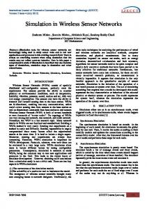
Mobile sensor node (attached to cow)
Fig. 1. Typical application pattern of micro-mobility in wireless sensor networks: mobile sensor nodes move freely in a limited area and communicate to the sink via a backbone of stationary wireless nodes.
I. I NTRODUCTION An increasing number of sensor network applications share a common pattern: mobile sensor and actuator nodes move freely in an area that can be covered by a backbone of stationary nodes. In these applications, sensor nodes are deployed on mobile objects such as animals, goods, or humans, to track their activities (see Fig. 1). Relevant examples include: tracking and monitoring of humans, e.g., to allow real-time clinical information from sensors attached to ambulatory patients [1]; habitat monitoring and tracking of animals [2] [3] [4]; and tracking and monitoring of objects [5] [6] [7]. The common setting of these applications is micro mobility, i.e., the movement of nodes is confined to a limited area such as a floor or a building. Due to their mobility, sensor nodes need to frequently select a new routing parent from the set of stationary backbone nodes. Current protocols for data collection and dissemination in sensor networks, such as CTP [8], do not anticipate this degree of mobility and do not provide the required mechanisms for handling frequent topology changes. In this paper we introduce MobiSense, a system architecture for energy efficient communication in micro-mobility sensing scenarios. MobiSense is a cross-layer architecture addressing both medium access control and routing to meet the following practical application requirements: • Reliable mobile sensing with low-latency communication and handoffs: the target applications require reliable low-latency data collection from mobile nodes,
Backbone of stationary sensor nodes
•
• •
•
and minimal additional latencies should be added when mobiles hand off from one backbone node to another. Energy-efficient communications: nodes should dynamically adjust duty-cycles in the presence of mobility and traffic variations to achieve very-low energy consumption. High throughput: the system should support high rate data collection in a network with several mobile nodes. Dynamic and distributed management: it should use distributed network formation and dynamic scheduling to efficiently handle frequent joins and leaves of mobiles. Two-way communications: it should offer reliable communication upstream (sensor to sink), downstream (sink to sensor).
This paper makes three main contributions: •
•
•
First, we introduce efficient mechanism for rapid network information gathering and rapid network (re)admission and convergence, both critical for energy-efficient micromobility with low-latency handoffs. Our mechanisms eliminate excessive overhearing and reduce network discovery time and (re)admission delay. Second, we develop distributed network formation, and dynamic scheduling mechanisms for handling frequent joins and leaves from mobile nodes in the network. Third, we describe downlink scheduling and two-way end-to-end communications which enable MobiSense to route data and to avoid disseminating data downstream.
This paper is structured as follows: In Section II, we review previous work on mobility in sensor networks. Section III identifies design challenges and introduces the architecture
of MobiSense. The system architecture of MobiSense is described in detail in Section IV and evaluated in Section V. Section VI discusses future work and concludes the paper. II. R ELATED W ORK In general, mobility in WSNs can be classified into three categories: sink mobility, mobile elements, and mobility of users/nodes. In [9] and [10] the authors use a mobile sink to prevent the hot-spot problem. The sink moves randomly or along a deterministic path. The goal is to reduce packet latencies and to redistribute the energy consumption and communication load evenly in the network. However, in many application scenarios, moving a sink frequently is not practical since nodes would need to reconstruct routing paths often, which requires significant amounts of energy. In [11] a mobile element solution is proposed, but the scenario is very different from ours: nodes collect data at rendezvous points and the focus is on scalability rather than real-time delivery. More related to our approach are the schemes proposed in [12], [13]. In these papers, nodes are attached to mobile users to perform sensing activities, but there are no concerns about energy-efficient mobility nor reliable real-time data transfer. Important concepts in MobiSense, such as distributed network formation and mobility network discovery, certainly exists in existing systems and standards. However, the mechanisms implemented in MobiSense are different. For example, in the 802.11-standard stations perform active or passive scanning across the full ISM (Industrial, Scientific, and Medical) band to discover nearby access points (APs). In contrast, MobiSense uses discovery slots on a common control channel in each super-frame to reduce excessive overhearing. Moreover, beacon messages allow nodes to collect key information (including traffic load and channel conditions) to perform an intelligent mobile-initiated handover with a minimal coordination overhead between cluster heads. In MobiSense, we provide a generic architecture, while the works mentioned in Section I, [1], [2], [3], [4], and [5], [6], [7] are tailored to a single use case. Additionally, they often use off the shelf MAC (medium access control)layers, hence do not make full use of the design space. Similarly, clustering protocols such as LEACH [14] do not consider mobility on their design. Overall, there is no system architecture for micromobility applications provided by the community. This papers aims to fill this void. III. M OBI S ENSE OVERVIEW In this section we discuss design challenges specific to (micro)-mobility that are not addressed by established protocols for collection or dissemination in static deployments [8]. We focus on a hybrid network architecture with a field of mobile sensors connected via a backbone of fixed low-power wireless nodes. A. Design Challenges and Choices Designing a reliable mobile sensing network brings a set of specific challenges. For example, Mobility causes frequent
topology changes, and adapting the full network is timeconsuming and costs a lot of energy and signaling overhead. If we disregard link dynamics, topology changes mainly affect the mobile nodes, while the backhaul is intact. The strain on network formation and re-formation is hence in at interface between cluster-heads and mobiles. Local scheduling allows to minimize overhead and well-defined beacon and access-slots speed up network (re)admission. High throughput adds to the challenge. It is well known that single-channel networks have limited bandwidth and cannot provide scalable throughput. It is thus natural to use multi-channel communications to enhance network performance [15], [16]. However, multi-channel communications could increase network discovery time, and reliable multichannel communication requires careful management of the channel resource and possibly clustering of the network to limit the broadcast domain of nodes. Clustering and multichannel communications has been found to significantly increase the reliability [17], timely data delivery [18], and throughput [15], [16], [19] of wireless sensor networks. The desire for energy efficiency limits the design space further. Since we would like to support high churn networks, energy-efficiency cannot be achieved by centralized network formation. In centrally managed systems, a node that intends to join the network will require the join request/reply message to be propagated to/from the manager, causing additional energy consumption and stealing bandwidth from the effective communication. If topology changes are frequent, the impact on goodput and lifetime can be significant. Thus, a distributed network formation is a natural choice to address this issue. B. Architecture Overview MobiSense is a hybrid architecture combining a fixed infrastructure network and mobile sensor nodes (see Figure 2). The system automatically organizes nodes into a clustertree topology and exploits multi-channel communication to ensure contention-free clusters. The fixed infrastructure is a reliable, high throughput backhaul network that supports mobility at walking speeds. MobiSense implements a dutycycled multi-channel medium access and network protocol that provides reliable data transfer, fast handovers and dynamic and distributed on-demand transmission scheduling. A distributed scheduling mechanism organizes communication super-frames into admission mini-slots, uplink and downlink data transmission slots, and discovery (beaconing) slots. The use of discovery slots eliminate passive and active scanning on unused channels, while the admission mini-slots allow rapid network convergence and low hand-over latency. Additionally, the use of dedicated uplink and downlink slots enables twoway communications, i.e., from the mobile nodes to the sink and vice versa. IV. M OBI S ENSE S YSTEM A RCHITECTURE MobiSense combines a stationary backbone operating under contention-free multi-channel communication with mobile nodes that move freely between clusters much like mobiles in a
cluster-heads send probes on a common channel M
M
M
CH
CH
CH network discovery slots (ND)
CH
MN mobile nodes wake-up on the same channel to listen to those probes, which prevents overhearing, while the discovery delay is constant
sink
backbone network
Fig. 2. Example of personal mobility in a multi-channel and clustered network. Nodes are organized into clusters, where infrastructure nodes act as cluster-heads. Mobile nodes move between clusters much like mobiles in a cellular network. Multi-channel communications allow contention-free clusters, reliability, high throughput and low-latency handoff.
Fig. 3. An example of the Rapid Network Information Gathering scheme used in MobiSense. During the Network Discovery Slots, each clusterheads broadcast small probe messages on a common channel. Nodes in the DISCOVERY state listen to those probe messages for a rapid network information gathering.
randomly selected access mini-slot
synch slot
cellular network. Our design has been driven by the following concerns: • rapidly changing link dynamics associated with mobile node movement cause the network to experiment a high degree of handoffs (join/leave requests) of mobile nodes. • central management of a contention-free network schedule for every node that hands off or propagating every join request to the manager is energy prohibitive. • enabling high throughput or maintaining a network schedule conflict-free in a large high churn network under single-channel communication is impractical. • many systems also need downlink communication, be it for dissemination of actuator commands, remote reconfiguration of mobile nodes, or simply to enable IP-based communication from mobiles to gateway. This section presents the key mechanisms that enable MobiSense to address these concerns. The first is to use clutering and multi-channel communications to segment the network and limit the broadcast domain of nodes. By having clusters operate on individual channels, cluster heads dynamically schedules local communication to maintain reliable high-throughput matched to the traffic demands of individual mobile nodes. The second is low-latency handoffs and lowoverhearing. The use of a well-defined beaconing period on a predetermined channel allows mobiles to rapidly gather network information without needing to overhear on multiple channels to discover the network, and a well-defined access window allows for rapid (re)admission when nodes decide to perform handover from one cluter to the next. The third is a mechanism for dynamically scheduled downlink communication to enable two-way end-to-end communication. A. Minimizing handoff latency and overhearing To minimize latency and idle listening during handoffs, we introduce network discovery beacons on a predetermined channel at well-defined times, followed by a dedicated access period in which mobiles can request to (re-)join the network. 1) Rapid network information gathering: In MobiSense, we eliminate unnecessary overhearing by introducing network discovery ND slots (see Figure 3) in which the sink and the cluster heads advertise information on a common channel (receiving nodes do not replay to those messages during the ND slots). The ND message from a cluster-head is sent at a
CH Node
downlink slots
scheduled slots node sleeps node send join request
node wakes up and listen to SY slot
Fig. 4. An xample of a cluster-head sub-frame that shows the synchronization slot, the downlink slots, the scheduled slots, and the access mini-slots. A mobile node attempts to join that cluster after selecting a random access mini-slot.
well-defined power level and contains information about the channel it uses for communication, the current cluster size and the timing of its access window (see below). Mobiles that want to join the network, or hand off from one backbone node to another, listen to these slots to gather network information and build prioritized lists of access points based on received signal strengths and cluster sizes. This scheme has many advantages: it eliminates the need to scan all 16 channels to find the network (hence minimizes overhearing), allows for a constant network discovery delay and it prevents unsuccessful join attempts to clusters that are already full, 2) Rapid network (re)admission and convergence: In MobiSense, the scheduled data slots are followed by a dedicated access period organized into a number of access mini-slots (AmS). The access period allows to avoid collisions between data transmissions and join requests. Nodes that intend to join the network do so by selecting a random access minislot in which they send their join request message (see Figure 4). Under moderate contention scenarios, the collision probability under random selection of the access mini-slot is very low, resulting in a low (re)admission delay and fast network convergence. In MobiSense, nodes join clusters and are admitted by the cluster head. No join request messages are propagated to the sink node. This distributed network formation also contributes to faster network convergence. To save energy at backbone nodes, MobiSense dynamically adjusts the access window size (AW ), i.e. the number of minislots in the access period. As the cluster size grows (i.e. the amount of remaining resources decreases) we decrease the access window to allow the backbone node to enter sleep mode earlier. Specifically, let Cmax and C be the maximum
active yes
Pr < Pth ?
no
slot release joinTimeOut
discovery
join request
Fig. 5. MobiSense Handoff Scheme: a mobile node constantly monitors the received power from its cluster-head. If the received power is below the sensitivity threshold, it first announces its departure from that cluster, and secondly, it listens on a common channel during a constant number of slots to search for a new cluster. Excessive overhearing on multiple channels is avoided, while the discovery delay is constant.
and current cluster size, respectively. Then, we allocate � � � � C Cmax − AW = 2 2
(1)
time slots for the access window. Each time-slot in AW is further subdivided into N mini-slots, creating a total of AW m = N · AW
(2)
mini-slots. The implementation of MobiSense evaluated in this paper uses Cmax = 8 and N = 4. Note that join request messages are small (on the order of a few bytes) so the multiplexing of time-slots into N mini-slots is feasible. Moreover, mobile nodes can compute AW m based on the predetermined constants N and Cmax and the information broadcast in the ND messages. While a smaller access window saves energy at backbone nodes, it could possibly increase collision probability and hence the re(admission) delay. However, recall that mobile nodes prioritize backbone routers with small cluster sizes and do not seek access to nodes with C = Cmax , so there is an inherent regulation of admission requests. Cluster heads initially have C = 0 which allows for fast network formation in dense networks where multiple nodes will seek access to the same cluster simultaneously. In MobiSense mobile nodes themselves decide if and when to hand off, and the ND messages allows it to gather sufficient information to make an informed handover decision. This technique eliminates signaling overhead between the backbone nodes involved in the handover. In the implementation of MobiSense evaluated in Section V we trigger a handover decision when the RSSI of packets from the current clusterhead drops below a power threshold of −75dBm. This value is based on previous studies which found that it can guarantee packet reception ratios above 95% [15], [20]. We then attempt to access the backbone of smallest cluster size whose ND packet was received with a RSSI over the threshold. If no such backbone router exists, we stay in the same cluster. Figure 5 depicts the handoff process on a mobile. B. Reliable energy-efficient high-throughput communication MobiSense relies on clustering [15] to enable reliable, energy efficient, high throughput communication. Each sensor node in the stationary backbone operates as cluster head to
which mobile sensor nodes can connect. Clustering allows us to 1) use multi-channels communications to ensure high throughput, 2) manage the network and communication schedules locally to limit control traffic, and 3) schedule traffic on a per-cluster granularity to enable reliable energy-efficient communication. 1) Multi-channel communications: MobiSense explores multi-channel communications to increase network throughput and to simplify network management. It is well-known that the throughput scales poorly with the number of nodes in dense multi-hop deployments. Improving the situation by contentionfree medium access protocols is not easy in a mobile scenario: link dynamics and node movements invalidate simple heuristics such as two-hop slot reuse, and it is hard to maintain a global conflict-free schedule under network churn. In MobiSense, adjacent cluster-heads operate on different channels. This reduces interference between clusters and allow each cluster-head to schedule traffic for its members without global coordination. In addition, multi-channel communication allows some clusters to multiplex the backhaul, while the remaining ones transmit to and/or receive data from the mobile nodes that they serve. These concurrent transmissions increase network throughput. As we will show in the evaluation section, the MobiSense throughput increases linearly with the data rate up until a saturation point. 2) Distributed network formation and dynamic scheduling: In MobiSense, join requests are processed locally by clusterheads, enabling distributed network formation. Each clusterhead determines communication schedules locally, without any signaling with other nodes. Since the scheduling is performed locally, it can also be done dynamically. Cluster-heads adapt the local schedule based on the number of mobile children and their data rates with little overhead (see Figure 6). 3) Scheduling for energy-efficient reliable communication: As mentioned above, clustering the network per stationary node efficiently reduces the collision domain of mobile nodes, and the scheduling can be done locally with a high reliability. A cluster-head acts as relay and schedules communication for the mobile nodes that it serves. For relaying, cluster heads maintain separate buffers for uplink and downlink communication. MobiSense organizes communication super-frames into downlink and uplink data transmission slots, admission minislots, and discovery (beaconing) slots. The downlink and the discovery periods are fixed, while the uplink period (scheduled slots) is dynamic and depends on the demands of its children. Communication schedules are based on the concept of coordinated transmissions/receptions [21]. In the first half of the superframe, some cluterheads serve their mobile nodes while the others communicate with the sink. In the second half of the superframe, the roles are reversed. To balance traffic, the sink attempts to assign an equal number of clusterheads to backhaul on each half of the superframe. This assignment is done by the sink when the cluster is granted access. Within each backhaul period, the sink node allocates communication resources to clusterheads using a proportionally fair mechanism that allows
Super-Frame Sink discovery period
scheduled uplink slots discovery beacons
access mini-slots
CH1 cluster send data
MN1
downlink period scheduled uplink slots
CH2 downlink period
MN2
randomly selected access mini-slot
MN3 node wakes up and listen to SY slot
D
data slots
S
synchronization slots
access mini-slots
CH
cluster-head
node send join request
MN
mobile node
Fig. 6. A distributed scheduling mechanism organizes communication super-frames into admission mini-slots, uplink and downlink data transmission slots, and discovery (beaconing) slots.
to share backhaul bandwidth reasonably also during tempory overload. Figure 6 illustrates an example with a sink node, two clusterheads (CH1, CH2) and three mobile nodes (MN1-MN3). The sink initiates the super-frame by sending a synchronization packet. This packet carries the schedule for communication between cluster-heads and the sink. Similarly, cluster-heads send synchronization packets in each super-frame to inform their mobile nodes about any changes in their uplink and downlink transmission opportunities. To understand the scheduling, first observe the sink node. Since it only has data to transmit downstream to MN2 via CH2, cluster-head CH1 remains asleep during the downlink period. After the downlink period has finished, CH2 enters into a backhaul transmission to the sink, while CH1 services its mobile nodes. CH1 does not have any data to transmit dowsntream to its children, hence the cluster remains idle throughout the downlink period and its mobile transmits a data packet in the uplink period that follows. In the second part of the backhaul scheduling, CH1 transmits upstream to the sink, while CH2 services its cluster. Note that the mobile nodes attached to CH1 and CH2 have different bandwidth requirements and MobiSense can deal with this seamlessly. To illustrate the relay capabilities of cluster-heads, observe that CH2 relays a unicast data packet originated from the sink to a mobile node (MN2). Now observe that the third mobile node signals its intention to (re)join the network by sending a join request message to CH2 after selecting a random access mini-slot. Finally, during the network discovery period, each cluster-head sends a small beacon message on a common channel. Due to its simplicity we use reference broadcast synchronization (RBS) [22] to synchronize nodes. Nodes within a cluster synchronize with their cluster-head and cluster-heads synchronize with the sink. Since synchronization packets are transmitted in every super-frame, the network can maintain high-precision global synchronization of all nodes. However, in its current implementation, MobiSense does not maintain an absolute network time: synchronization packets of cluster heads only act as relative time reference for the nodes it serves.
S R1
U
unicast slots
B
broadcast slots
R2 S synchronization slots
Fig. 7. An example Downlink Scheduling. A parent notifies the intended recipients of their receiving schedules, during the the transmission of the synchronization packet. In this way, MobiSense saves energy at the receives, because it prevents packet dissemination.
C. Downlink scheduling and two-way communication Despite maintaining an adaptive collection tree, in MobiSense we additionally allow the sink to communicate to each node in the network, i.e., sink-to-any communication. This provides an efficient scheme to communicate configuration updates to individual nodes or to enact IPv6 communications over WSNs. Hence, we can avoid to disseminate data to all nodes in the network. For this, a cluster-heads in MobiSense schedule downlink transmissions. Cluster-heads inspects the downlink buffer, and they specify on the schedules, which nodes have data to receive during the downlink period. A proportional data allocation is applied when the time to transmit packets in the downlink buffer exceeds the downlink period. Note that broadcast packets are addressed to all, cluster-heads make all nodes in a cluster aware of incoming broadcast packets. To enable two-way end-to-end communications, a cluster-head inspects the network header to route packets. Received packets intended to nodes inside the cluster are placed into the downlink buffer for downstream transmission. While the nodes intended to nodes outside the cluster, are placed into the uplink buffer for upstream transmission. In the Figure 7, a cluster-head (S) has 5 packets in its downlink buffer to be transmitted downstream to recipients R1, and R2 respectively. These packets are 2 broadcast packets (B), 1 unicast packet (U1) for recipient R1, and 2 unicast packets (U2) to recipient R2. The sender makes the intended recipients aware of their receive schedules during the transmission of the synchronization packet. Since the broadcast packet is
addressed to both R1 and R2, they remain both awake to receive it. The receiving offsets, make the recipients to turn their radio off when there is transmission of unicast data that it is not addressed to them. V. E VALUATION In this section, we evaluate the design of MobiSense in simulations and testbed deployments. We show that MobiSense achieves a low handoff-latency and high throughput while maintaining high reliability and energy-efficiency. A. System Configuration MobiSense has been developed using the Contiki-2.5 [23] operating system, and evaluated on a testbed with telosb platform motes. We used Cooja (the Contiki Java Simulator) [24] for simulations, and a separate Java application to generate random mobility patterns in a 90mx90m grid. In our evaluation of MobiSense we used a payload of 94 bytes including MAC and Radio Duty-Cycle (RDC) headers. We configured MobiSense with a super-frame duration of 608ms. A larger value was not chosen since it would increase the packet latencies from any mobile to the sink node. Each timeslot has the duration of 8ms. We use a maximum of 8 mobile nodes per cluster. The network discovery period is 4 time-slots long, while the maximum duration of the scheduled downlink slots is equal to 7 time-slots. We varied the data rate of each mobile nodes from 2pps up to 14pps. For deployments we use our local testbed of 27 telosb nodes. We use 20 nodes as mobile nodes, 6 as cluster heads, and one as sink. We used channel 26 as the common channel that handles network admission. Channel 25 is operated as the backhaul channel, i.e, cluster-heads time-multiplex the use of this channel when transmitting upstream to the sink node. The remaining channels are assigned to the cluster-heads. B. Handoff and Network Convergence Latencies Handoff Latency: in MobiSense the handoff latency is divided into two parts: discovery, and (re)admission latencies. The discovery latency is a constant delay, because nodes use network discovery slots (see Section IV-A1). However, the (re)admission delay is not deterministic and depends on two factors: first, cluster heads synchronize their children on different phases, adding random offsets. Second, when multiple nodes are requesting admission the same cluster, collisions might occur, increasing the admission delay (see Section IV-A2). In this section we evaluate the worst case scenarios, i.e., a number of nodes move from one cluster to another at the same time and trigger the handoff requests simultaneously. We vary the cluster size from 1 to 7 and vary the number of mobile nodes that join that cluster from 1 to 8. Note, that we configured MobiSense for a maximum of 8 mobile nodes per cluster. Since the cluster size determines the access window (AW ), the goal is to observe how the variation of the access window and the size of number of admission mini-slots affects the handoff latency (see Figure 8).
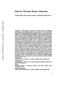
Figure 8(a) depicts the case where each time slot in the contention window of a cluster head provides 2 access minislots (N=2), while 8(b) depicts the case for 4 access minislots. In the worst case scenario, when 8 mobile nodes join a cluster simultaneously, the handoff latency is decreased by a factor of 7 by doubling the number of mini-slots per time-slot (compare Figures 8(a) and 8(b)). In the Figure 8(c) we show the impact of N on the handoff latency. We keep the cluster size constant (C=4, AW=2) while we vary the number of minislots per time-slot. The results show that MobiSense achieves small handoff latencies with a minimal overhearing (due to discovery slots). We can further decrease the handoff latency by increasing AW. However, this comes at the expense of extra energy consumption on cluster-heads. Overall, handoff delays averaging on 1 to 2 seconds can be easily handled by the buffers on the sensor nodes and are well within the deadline constraints of our targeted applications. Convergence Latency: we place mobile nodes in random starting positions and vary both the number of mobile nodes and the number of cluster-heads in the network. Figure 8(d) shows the network convergence latency is below 10 seconds in a MobiSense network of 27 nodes. These results show the impact of rapid network information gathering, rapid network (re)admission, distributed network formation and scheduling. C. Throughput Multi-channel communications and clustering allows to segment the network into small contention-free and dynamically scheduled clusters. By minimizing the broadcast domain of nodes we achieved high throughput, as neighboring clusters do not need to content for medium access. Figure 9(a) depicts the maximum throughput of a single cell in absence of neighborhood cells serving the sink node. We observe that when increasing the cell size and when increasing the data rate per node, the throughput increases linearly until a saturation point (horizontal lines). This saturation point is reached when a cluster-head can no longer accept data into its uplink buffer. Thus, the saturation point is the maximum capacity that a cell can deliver to the system. Figure 9(b) depicts the average system throughput. The results in the Figure were obtained through simulation in Cooja and in the testbed with the following parameters: 1 sink node, 6 cells, and 20 senders spread in our lab rooms and hallways. In both simulation and testbed the system throughput increases linearly with the data rate, until it reaches the saturation point of the system when the capacity of the backbone reaches its limit. Overall, we believe that these throughput rates are well within the application requirements and can even handle sudden traffic bursts. D. Reliability vs Throughput In this subsection we evaluate the system reliability with respect to the data rate. We particularly focus on the relation between the system saturation and reliability. As explained earlier, the system throughput increases linearly with the data
20 15 10 5 0
1 join 2 join 3 join 4 join
3.5 Average Handoff Delay (sec)
Average Handoff Delay (sec)
25
5 join 6 join 7 join 8 join
2
3
5 4 Cluster Size
6
3.0 2.5 2.0 1.5
0.5
7
1 join 2 join 3 join 4 join
3.5
5 join 6 join 7 join 8 join
3.0 2.5 2.0 1.5 1.0
1.0
1
8.0
4.0
4.0
5 join 6 join 7 join 8 join
Average Network Convergence Delay (sec)
1 join 2 join 3 join 4 join
Average Handoff Delay (sec)
30
1
3
2
5 4 Cluster Size
6
0.5
7
4 cluster-heads (sim) 6 cluster-heads (sim)
7.0 6.5 6.0 5.5 5.0 4.5 5
5
3 4 Mini-slots per time-slot (N)
2
7.5
10 15 Number of Mobile Nodes
20
(a) Variation of the handoff latency (b) Variation of the handoff latency (c) Variation of the handoff latency (d) Network convergence delay in with respect to C when the number with respect to C for N=4. with respect to N for C=4. a network with 4 and 6 clusterof access mini-slots per time-slot heads. (N=2). Fig. 8. Figures 8(a) and 8(b) show the impact of of the cluster size C and the number Figure 8(c) shows the impact of N on the handoff latency for C=4. Figure 8(d) shows the variation of the network converge delay with respect to the
8
6
4
2
Average Packet Reception Ratio (PRR)
Average System Throughput (kbps)
Average Cell Throughput (pps/node)
1.00
90 80 70 60 50 40
5
0.95
0.90
0.85
0.80
20 4
6
8 10 Data Rate (pps/node)
12
14
3
2 simulation - 20 senders testbed - 20 senders
2
4
6 8 Data Rate (pps/node)
10
0.70
0
2
6 4 Data Rate (pps/node)
8
10
(a) Variation of the average cell (b) Variation of the average system (c) Variation of the average system throughput with respect to the clus- throughput with respect to the data reliability with respect to the data ter size, and the data rate per node. rates. rates. The horizontal lines indicate saturation points Fig. 9.
4
0.75
30
2
without handoff (simulation) with handoff (simulation) testbed (w/o handoff)
testbed with 20 nodes simulation with 20 nodes
100
10
0
6
110
4 nodes 6 nodes 8 nodes
Average Duty Cycle (%)
12
1
0
2
6 4 Data Rate (pps/node)
8
10
(d) Node duty-cycle on mobile nodes under low, and high traffic conditions, as well as scheduling traffic overhead (0pps/node).
Average throughput in a cluster 9(a) and in the System 9(b). Average system reliability 9(c), and duty-cycle 9(d).
rate (see Section IV-B1). However, there is an inflexion after 6 pps when the system approaches its saturation point. Figure 9(c) shows that MobiSense reaches a multi-hop reliability of more than 95% when traffic is not saturated. After passing the saturation point of 6 pps reliability degrades. Although the system can accept more traffic than 6pps (see Figure 9(b)), we observe that the buffers at the clusterheads become saturated, resulting in an increase of discarded packets. E. Duty Cycle vs Throughput In this subsection we evaluate (1) the duty cycle of MobiSense under low and high traffic scenarios, and (2) the overhead of control traffic, i.e., time synchronization, scheduling, etc. Figure 9(d) depicts the duty cycle of our mobile nodes for different data rates. Cluster heads show a similar duty cycle. However, since cluster heads are part of a fixed infrastructure, we do not discuss them in detail. Scheduling and Signaling Overhead: In the first scenario, we operate the system without data transmission. The goal was to observe how much the synchronization and control traffic contributes to the overall network duty-cycle. In Figure
9(d) this corresponds to 1.31% at 0pps. At this point, the only traffic generated is control traffic such as keep alive messages from children to their parents to maintain schedules, and synchronization packets from parents to their children. Low and Hight Traffic: under low traffic scenarios, by doubling the data rate from 0.1pps/node to 0.2pps/node, mobile nodes experience duty-cycles of 1.31% and 1.35% respectively. The later cost increases only 2% relatively to the first (1.31%), with 50% increase in the node data rate. This demonstrates that MobiSense is very energy efficient. For high data rate scenarios, the duty-cycle increases linearly with the data rate, and it still below 6% for data rates of 10pps/node. For example by increasing the data rate 10 times in the range from 1pps/node to 10pps/node, it only results in an increase of 3.3 times on nodes duty-cycles. This demonstrates our assumption that by using clustering, multichannel, and scheduled communications, not only limits the broadcast domain of nodes, it also improves significantly our energy savings. F. Limitations After evaluating the core aspects of MobiSense, we discuss limitations of the design and our current implementation.
There are two main limitations in MobiSense: scalability, and synchronization overhead. Firstly, the current system is designed to test micro-mobility in WSNs. Hence, our implementation only allows for one level of cluster heads. In our ongoing work, we are implementing support for hierarchical cluster heads, i.e., cluster heads to which other cluster heads and mobile nodes can connect. Second, changes in traffic demands of mobile nodes inside a cluster or the arrival or departure of a mobile node trigger changes on the schedule of all nodes in a cluster. These changes are propagated to child nodes through the synchronization packet, allowing a node to react immediately to changes of its transmission schedule. This requires every node to listen to synchronization packets transmitted by its cluster-head in each super-frame. However, this causes extra energy consumption in low traffic scenarios when a node does not have any data to send to its cluster-head during consecutive super-frames. We are working to offset this limitation, by introducing event-triggered transmissions for mobile nodes that operate in low-traffic scenarios. VI. F UTURE W ORK AND C ONCLUSION In this paper we presented MobiSense, a system architecture for reliable and energy-efficient micro-mobility. Our results demonstrate reliable data transfer and rapid hand-overs with a low radio duty-cycle and high energy-efficiency. MobiSense achieves reliability above 95% for data rates upto 6pps/node. We show that our proposed mechanisms for rapid network information gathering and fast network (re)admission and convergence allow for low-latency handoffs. As for energyefficiency, our results show that MobiSense is energy-efficient even on high data-rate scenarios with duty-cycles of 4% at 6pps/node. While the system is designed as a generic architecture for micro-mobility applications, we have built it especially with two planned deployments in mind: (1) industrial automation, i.e., closed-loop wireless sensor feedback to control a small paper mill on our campus, and (2) patient monitoring and control in a hospital and elderly care. Future work will also focus on addressing the main limitations of MobiSense in these deployments and enacting mobile IPv6 over WSNs. R EFERENCES [1] O. Chipara, C. Lu, T. C. Bailey, and G.-C. Roman, “Reliable clinical monitoring using wireless sensor networks: Experiences in a step-down hospital unit,” in Proceedings of ACM Sensys’10, November 3-5, 2010, Zurich, Switzerland, 2010. [2] Y. Guo, P. Corke, G. Poulton, T. Wark, G. Bishop-Hurley, and D. Swain, “Animal behaviour understanding using wireless sensor networks,” in Proceedings of IEEE LCN’06, 2006. [3] V. Dyo, S. A. Ellwood, D. W. Macdonald, A. Markham, C. Mascolo, B. Pasztor, , N. Trigoni, and R. Wohlers, “Poster abstract: Wildlife and environmental monitoring using rfid and wsn technology,” in Proceedings of ACM Sensys’09, 2009, Berkeley, CA, USA, 2009. [4] A.-J. Garcia-Sanchez, F. Garcia-Sanchez, F. Losilla, P. Kulakowski, J. Garcia-Haro, A. Rodrguez, J.-V. Lpez-Bao, and F. Palomares, “Wireless sensor network deployment for monitoring wildlife passages,” Sensors 10, 2010. [5] S. C. Lee, T. G. Jeon, H.-S. Hwang, and C.-S. Kim, “Design and implementation of wireless sensor based-monitoring system for smart factory,” ICCSA 2007, 2007.
[6] H. Wang, Y. Hou, and Y. Xin, “Plant running management based on wireless sensor network,” in Proceedings of ICMTMA, pp. 138 – 141, 2009. [7] M. Li and Y. Liu, “Underground coal mine monitoring with wireless sensor networks,” ACM Transactions on Sensor Networks (TOSN), 2009. [8] O. Gnawali, R. Fonseca, K. Jamienson, D. Moss, and P. Levis, “Collection tree protocol,” in Proceedings of ACM Sensys’09, November 4-6, 2009, Berkeley, CA, USA, 2009. [9] A. Kinalis and S. Nikoletseas, “Scalable data collection protocols for wireless sensor networks with multiple mobile sinks,” ANSS ’07., pp. 60 – 72, 2007. [10] V. N. and D. Stevanovic, “Sink mobility in wireless sensor networks: When theory meets reality,” SARNOF.2009, pp. 1 – 8, 2009. [11] S. Basagni, A. Carosi, and C. Petrioli, “Controlled vs. uncontrolled mobility in wireless sensor networks: Some performance insights,” 60th IEEE Vehicular Technology Conference, 2007, pp. 269 – 273, 2007. [12] E. Lee, Y. Choi, S. Park, D. Lee, and S.-H. Kim, “A data delivery mechanism to support mobile users in wireless sensor networks,” The 9th International Conference on Advanced Communication Technology, vol. 1, pp. 245 – 250, 2007. [13] S.-S. Kim and A.-S. Park, “A novel model for user mobility in wireless sensor networks,” AINAW’07, vol. 2, pp. 647 – 652, 2007. [14] M. H. Handy and D. M. Timmermann, “Low energy adaptive clustering hierarchy with deterministic cluster-head selection,” 4th International Workshop on Mobile and Wireless Communications Network, 2002. [15] Y. Wu, J. A. Stankovic, T. He, J. Lu, and S. Lin, “Realistic and efficient multi-channel communications in wireless sensor networks,” INFOCOM’08, pp. 1193 – 1201, 2008. [16] G. Zhou, C. Huang, T. Yan, T. He, and J. A. Stankovic, “Mmsn: Multi-frequency media access control for wireless sensor networks,” INFOCOM 2006, pp. 1 – 13, 2006. [17] K. S. J. Pister and L. Doherty, “Tsmp: Time synchronized mesh protocol,” in Proceedings of the IASTED International Symposium on Distributed Sensor Networks,, 2008. [18] Y. Kim, H. Shin, and H. Cha, “Y-mac: An energy-efficient multi-channel mac protocol for dense wireless sensor networks,” IPSN, 2008. [19] O. D. Incel, P. Jansen, and S. Mullender, “Mc-lmac: A multi-channel mac protocol for wireless sensor networks,” 2008. [20] K. Srinivasan, P. Dutta, A. Tavakoli, and P. Levis, “Understanding the causes of packet delivery success and failure in dense wireless networks,” Computer Science Division, UC Berkeley, Tech. Rep., 2006. [21] C. Hoymann, A. Racz, N. Johansson, and J. Lundsjo, “A selfbackhauling solution for lte-advanced,” WWRF21-WG4-07, 2007. [22] J. Elson, L. Girod, and D. Estrin, “Fine-grained network time synchronization using reference broadcasts,” OSDI 2002, 2002. [23] A. Dunkels, B. Gronvall, and T. Voigt, “Contiki - a lightweight and flexible operating system for tiny networked sensors,” in Proceedings of IEEE LCN’04, 2004. [24] F. Osterlind, A. Dunkels, J. Eriksson, N. Finne, and T. Voigt, “Crosslevel sensor network simulation with cooja,” in Proceedings of IEEE LCN’06, 2006.