MODEL AND METHODOLOGY FOR THE SYNTHESIS OF HETEROGENEOUS AND PARTIALLY RECONFIGURABLE SYSTEMS Florian Dittmann, Marcelo Götz
Achim Rettberg
Heinz Nixdorf Institute University Paderborn Fürstenallee 11, 33102 Paderborn, Germany email: {roichen,mgoetz}@upb.de
C-LAB University Paderborn Fürstenallee 11, 33102 Paderborn email:
[email protected]
ABSTRACT When reconfigurable devices are used in modern embedded systems and their capability to adapt to changing application requirements becomes an issue, comprehensive modeling and design methods are required. Such methods must respect the whole range of functionality of the reconfigurable fabrics. In particular, the heterogeneity and reconfiguration delay of modern FPGAs are important details. Comprehensive methods to exploit these characteristics within the integrated design of embedded systems are still not available. In this paper, we introduce a synthesis methodology for reconfigurable systems that respects the specific requirements of run-time reconfiguration. The methodology bases on profound concepts, and expands known notations and model techniques. 1. INTRODUCTION Modern embedded systems increasingly are multi-functional: They have a fixed core functionality and some application dependent behavior. For example, mobile phones basically serve as communication unit and therefore can connect to multiple networks (GSM, WLAN, etc.), which require different algorithms for transmission/reception that furthermore depend on the currently active application. Additionally, mobile phones offer organizer functionality, entertainment, navigation, etc. The computational hardware of such systems consists of a variety of processing units, including CPUs, DSPs, ASICs, and increasingly reconfigurable fabrics. The run-time reconfigurability of the fabrics thereby allows to react for multiple purposes, including applications which demand for high computing performance. Additionally to the adaptation to the different behaviors mentioned above, new updates can be loaded into the system (post-fabric reconfiguration). In order to consolidate reconfigurable logic as core parts within This work was partially funded by SPP 1148 Reconfigurable Computing of the German Research Foundation (DFG).
1-4244-0910-1/07/$20.00 ©2007 IEEE
such systems, synthesis and design space exploration methods are required that base on substantiated models. In this contribution, we shape and improve approaches and methods of embedded system design for the design of partially and run-time reconfigurable fabrics that themselves can be part of a complex systems. As an example, we consider modern FPGAs, which are characterized by partial reconfigurability, heterogeneity, a single reconfiguration port and notable reconfiguration time. Although being powerful extensions, the reconfiguration and the diversity of the FPGAs may become the bottleneck of the system if not properly considered during the design phase. Due to the heterogeneity (additional hard cores like multipliers, DSP units, distributed RAM, or even whole processors within the reconfigurable fabric), placement becomes complex, increasing fragmentation. Dynamic reconfiguration on one hand can adapt the system, on the other hand, however, consumes time and reconfiguration resources. In the area of embedded systems, the so-called platformbased design methodology [12] focuses on optimizing the system towards a specific application, while also offering freedom for extensions. We follow this concept and base our work on a run-time environment implemented on an FPGA. Such an environment offers flexibly combinable slots and an appropriate communication infrastructure. Moreover, we improve the concept of equally sized slots towards heterogeneity. Based on the platform-based design concept, we propose a model and methodology to explore the design of heterogeneous and partially reconfigurable systems. Therefore, we expand known notations and model techniques from system synthesis in order to include the characteristics of reconfigurable systems. Among these are the reconfiguration time, dedicated computation resources, heterogeneity, communication requirements, I/Os, etc. We also discuss a technique how to transparently include the reconfiguration latency into the scheduling. Furthermore, we allow multiple reconfiguration fabrics—thus having more than one reconfiguration port/controller in the overall system.
The rest is organized as follows: In the next section, we review related work. Then, we introduce the problem abstractly, including the characteristics of execution environments and the application areas. Section 4 reports on the proposed approach of extending known models and methodologies. We apply the concept on an example, before we finally conclude and give an outlook. 2. RELATED WORK Two approaches have influenced our work. We present them first, before giving a broader overview of further literature. The first approach bases on Blickle et al. [2]. Blickle et al. propose system design based on a specification graph, which consists of a problem graph and an architecture graph. The combination of all phases of the system synthesis is an important means: the specification graph GS , the allocation α, the binding β and the scheduling γ. Having all these four elements in a valid combination results in a valid overall system. The fundamental characteristic of the work is the inclusion of communication into the design as discrete nodes. Haubelt improves this concept significantly in [7, 8, 9]. He introduces hierarchy for raising the level of abstraction and for exploring reconfigurable hardware. The aim is architecture design for multiple purposes. Furthermore, he proposes the concept of hierarchical mapping edges, which significantly improves the specification graph model. However, Haubelt does not consider partial run-time reconfiguration in his approach. The second approach [1] shows a physically aware hardware-software partitioning scheme for minimizing application execution time. The target architectures are reconfigurable devices with partial dynamic reconfiguration capability. The authors consider the exclusiveness of the reconfiguration port and the need for adjacent free columns to place tasks. Similar to the Blickle/Haubelt approach, they start with task dependence graph. On basis of the Kernighan-Lin/Fiduccia-Matheyes (KLFM) approach they have developed a heuristic for synthesizing such task dependence graph on partially reconfigurable architectures. Results of the second approach form the basis for our work. However, we consider communication as an integral part and therefore integrate it into the synthesis and design space exploration. Furthermore, our approach also supports environments composed of multiple reconfigurable fabrics. Finally, we improve the concept of heterogeneity and allow differently shaped slots. Additionally, there exist further works in the field, of which we mention the most meaningful ones. Despite little consideration on nowadays heterogeneous FPGAs, [6] presents a sophisticated concept of modeling and optimizing run-time reconfiguration using evolutionary
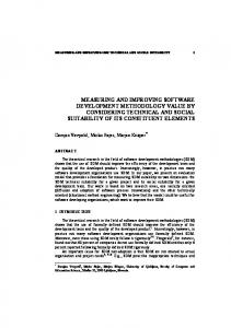
computation. The approach focuses on optimally reducing the run-time reconfiguration overhead during the HW-SW partitioning stage, which is done by detecting functional commonality. In [15], the authors describe a hardware-software partitioning and scheduling approach for dynamically reconfigurable systems. A method is presented, based on genetic and list scheduling algorithms, which can tackle multi-rate, real-time, periodic systems. The authors of [10] present HW/SW co-synthesis for run-time reconfigurable systems, relying on an exact algorithm (ILP) and a KLFM-based approach. Their ILP considers the single reconfiguration controller bottleneck and reconfiguration time hiding. However, while scheduling, they do not consider physical task placement constraints. Finally, SPARCS (Synthesis and Partitioning for Adaptive Reconfigurable Computing Systems) [16] is an integrated design system for automatically partitioning and synthesizing designs for reconfigurable boards with multiple field-programmable devices. Run-time reconfiguration is considered only rudimentarily. To summarize, our work extends the presented approaches, e. g., by the possibility of exploring a system with multiple partially reconfigurable fabrics. In general, we focus on the comprehensive mapping of problems to partially reconfigurable environments and include all necessary constraints, so far not combined in the approaches presented above. 3. PROBLEM DESCRIPTION The behavior of the targeted embedded systems is composed of some core functionality (e. g., determined by the application environment) and additional dynamically selected functionalities (e. g., triggered by user interaction). Dynamically arriving applications occupy the left over or temporarily unused resources. On CPUs, the free processor utilization can be used. On reconfigurable devices, we can load new configurations, e. g. bitstreams. Thereby, the run-time environment must be designed open-minded in order to allow new tasks to enter the reconfigurable fabric. The problem to be mapped on our system is given by a universal directed task dependence graph G(V, E). The execution is similar to a homogeneous dataflow graph, where processes are only activated for execution if all their predecessors have finished their execution. The system under design is a combination of computation resources such as processors, ASICs, and reconfigurable devices (ref. to Figure 1). Without loss of generality, we focus on the latter only relying on an execution environment that abstracts the challenging details of dynamic resource allocation on such FPGAs. Several groups have proposed such run-time environments for task execution on FP-
RAM
MAC
Slot 4
Slot 3
Slot 1 Slot 2 RAM
I O
Slot 5
I O
CPU
MAC
Slot 6
RAM
Slot 0
MAC
CPU
Slot 7
ASIC
IO FPGA
FPGA ...
Fig. 1. Schematic draft of an exemplary system focusing on the execution environment based on FPGAs. GAs. Some examples of such reconfiguration environments are the Erlangen Slot Machine [3] or similar approaches [4, 11, 20]. Modern reconfigurable devices, like the Virtex 4 FPGA, are increasingly heterogeneous. They are no longer completely fine-grained devices, and offer more and more additional cores, e. g., DSP cores, etc. Usage of such resources can lead to more area-efficient and faster implementations. Moreover, the FPGA is divided in areas of specific size, similar to a tile-structure. According to Xilinx, the reconfigurable parts of the FPGA are similar to the division of the clock network. Thus, we will have a number of heterogeneous slots arranged on the FPGA. The slots can be reconfigured individually, however using the single and mutually exclusive reconfiguration port. The intermodule communication of the slots is defined by the environment and can range from direct wiring to a common bus for all slots. For example, [3] allows several different modes of communication. Concerning the arrangement of the slots, modern devices, like Xilinx Virtex 4 FPGA, free us from the limitation of only whole column based reconfigurable areas. Based upon theses characteristics, in our model of a runtime environment, the reconfigurable device will be tiled. The tile size and functionality is not homogeneous. Additionally, we rely on a static communication structure (see also Figure 1). As a consequence, application mapping becomes more complex, since new tasks to be executed on slots could require specific resources within these slots that are not available. Generally, the diversity, in particular dedicated resources are welcome concerning performance, however, they must be treated appropriately. Furthermore, FPGAs suffer a long reconfiguration time. Heterogeneous FPGAs might decrease the reconfiguration time, as more functionality is realized by fewer reconfiguration bits (with the drawback of limited flexibility). Still, the reconfiguration overhead, i. e., the time needed for carrying out reconfigurations, can be considered as proportional to
the area under reconfiguration. Partial reconfiguration allows us to hide reconfiguration time, however an additional limiting factor is the single reconfiguration port that must be used mutually exclusive. If our system hosts more than one FPGA, we can also reconfigure two areas at the same time if those areas are not present on the same FPGA, using, therefore, two different reconfiguration ports. To summarize, by using our run-time environment model we are taking into consideration scenarios, where heterogeneous resources compose the execution platform of modern embedded systems. The usage of an execution environment is close to platform-based design, i. e., we optimize the platform for a set of behaviors. Thus, we can formulate our design using two graphs: the problem graph and the architecture graph. Together, both are the specification of the system as introduced by [2]. Additionally, there exist mapping edges between the problem graph and the architecture graph, which describe feasible bindings of processes to resources. We annotated the edges with weights such as the time or power needed. Altogether, specification graphs and, in particular, the mapping edges are the underlying model for the design space exploration. As a consequence, proper mapping edges are crucial for reasonable results. 4. PROPOSED APPROACH In our work, we start from a high level of abstraction comprising of the system architecture and the problem description both given as graphs. 4.1. Objective The aim is to derive a binding that is optimal in a multidimension design space. Such Pareto-optimal points are computed by a design space exploration. In particular, our methodology bases on a reconfigurable execution environment and the problem given as a task dependence graph. For example, with our approach we are able to improve the response time and to reduce the power consumption. 4.2. Outline In order to accurately map the above introduced task dependence graph onto an execution environment, we extend methods from the literature in this section. Those methods are in the domain of system synthesis. We define synthesis as creating implementation details which are left out of the specification. However, we do not decide on the kind and number of system components (allocation), which is part of the system-level synthesis. Synthesis is a complex task and most often is divided into the sub-steps allocation, binding, and scheduling [5, 2]. The sequence of the steps is not fixed, combination of steps
time
T1
G
C0
RT1
T1 Slot 1
T2
T2
T1
C2
Slot 2
T2
RT1
T1 RT1 T3
problem GP graph
T3
T2
G*
C3
Fig. 2. Task dependence graph G, extended by RT nodes to G∗ , and corresponding problem graph GP with communication nodes and reconfiguration phases. can be of additional benefit. Fundamental to the steps is a system specification. Only the combination of all phases of the system synthesis, i. e., the system specification, the allocation α, the binding β and the scheduling γ (cf. [2]), will result in a valid overall system and lead to an implementation. 4.3. Formal Model The reconfigurability (reconfiguration duration and mutually exclusive reconfiguration port), which affects space and time, demands for a model that allows comprehensive exploration. In order to be able to respect the specific needs of (partially) reconfigurable devices, we extend our initial task dependence graph G via several steps into a problem graph GP (VP , EP ). Every initial node of G gets an additional input from its reconfiguration phase RT. Thus, we can derive an extended graph consisting of execution and reconfiguration nodes (T and RT). We call this graph G∗ , with V ∗ = VT ∪ VRT . As this fundamental step is new to the domain of system synthesis, it requires special care in the mapping phase. However, by adding the reconfiguration phases as integrated vertices of the task graph, we do not extend the modeling set of the synthesis and can basically rely on already existing methods. Furthermore, the specific RT nodes for each task node T implicitly introduce reconfiguration prefetching to the model, as the RT nodes can be scheduled independently. As proposed by Blickle et al. [2], we add the communication vertices and derive the problem graph GP (VP , EP ) from G∗ in order to respect the communication. Figure 2 displays the result. Having explicit nodes for communication forms the basis for comprehensive synthesis of par-
RT3
Slot 3
T2
T3
Fig. 3. Left the task dependence graph, right a Gantt chart of a possible schedule: Conflict as Task 4 was reconfigured before Task 2 was executed.
tially reconfigurable hardware, as communication requirements are now part of the system specification. Thus, we introduce communication needs of reconfigurable devices to the design process. If we directly schedule this problem graph, we might get into a conflict. As Figure 3 shows, tasks could be reconfigured, i. e., loaded on an FPGAs, without being executed. In particular, scheduling algorithms dispatching tasks in the order of ASAP (as soon as possible) scheduling would schedule the reconfiguration phases subsequently without respecting whether the corresponding tasks have been executed. The scenario depicted in Figure 3 must be prevented. To avoid this conflict, we define intervals during which the area of a task must be preserver on an FPGA, i. e., the slot that has just been reconfigured must stay in this configuration until the execution of the corresponding task has been taken place. We apply so-called life periods as displayed in Figure 4. Life periods or intervals are often used in the domain of register allocation and initially help to reduce the amount of registers needed. Such intervals are respected during the scheduling phase and are often solved using graph coloring, e. g., by the left-edge algorithm or similar approaches [13, 17, 19].
RT1
C2
Interval
C1
T4
RT4
RT2
T1
RT2 C2 T2
RT3
C1
Interval
RT3
RT1
T1
T3
RT2 T3
RT1
Interval
task graph
T3
C3
Fig. 4. Problem graph with intervals/regions.
Slot_type A RT Port
RT1
Slot_type B
reconfig. time
RT Port
GP I/O
Bus
GA
Fig. 5. Exemplary architecture graph with two slots, reconfiguration port, bus, and I/O. Note that by attaching life periods, there is no fundamental change in the formal model or a reduction to a specific subset necessary. Thus, we can still apply known concepts from system synthesis. The information of the life periods can be easily used by the scheduling algorithm to prevent the conflict described above. In order to achieve separation of behavior and structure, as proposed in the Y-chart approach by Gajski and Kuhn [5], we add a separate graph for the architecture similar to Blickle et al. [2]. Thus, the second part of our formal model is this architecture graph GA (VA , EA ). The architecture of our system (run-time execution environment) consist of the slots, the communication and the reconfiguration port. Nowadays, FPGAs have one reconfiguration port only that must be accessed mutually exclusive. The reconfiguration port usually does not have connections to the other resources of the FPGA (ICAP and special architecture being the exception). Figure 5 shows an example. To finally combine the two graphs, we derive a combination of the problem graph GP and the architecture graph GA into the specification graph GS = GS (VS , ES ) (cf. [2]). The vertices of the specification graph consists of the vertices of the problem and the architecture graph VS = VP ∪ VA , while the edges are the edges of the problem and the architecture graph, as well as mapping edges EM : ES = EP ∪ EA ∪ EM . 4.4. Mapping For completing the specification graph, we map nodes of GP to nodes of GA by mapping edges EM . Therefore, the three elements of the problem graph must be investigated in more detail. The computational vertices VT are assigned to slots, on which they can be executed. The tasks might fit into different slots, resulting in multiple mapping edges. We attach the mapping edges with related information when executing this task in the selected slot. In particular, we annotate the execution time, which is essential to derive a reasonable schedule. Furthermore, additional weights like power consumption are possible and can be used to improve the results of the binding phase. Similar, the communication nodes are mapped to communication resources. Again, we attach specific characteristics to the edges, like duration of the communication or the
T1
execution time
Slot_type_ A
Fig. 6. Specification graph with mapping edges of task and reconfiguration phase to slot and slot + reconfiguration port, respectively.
load of a bus. This information again constrains the scheduling and binding. Finally, the reconfiguration vertices VRT must be mapped to the architecture graph. Basically, a reconfiguration phase can only take place if two constraints are fulfilled: First, the reconfiguration port must be free; second, the slot to be reconfigured must be available. A mapping edge must respect this requirement. We use the concept of hierarchical edges proposed by Haubelt [7] to denote the need of both reconfiguration port and slot. Figure 6 shows the concept. In general, a mapping edge for a reconfiguration phase is an edge EM that has one vertex of VP as source and at least two vertices of VA as sink. One of the sink vertices is always the reconfiguration port. We map the reconfiguration phases on the basis of the already placed mapping edges, i. e., considering allocated slots for the associated tasks only. Thereby, we attach the specific reconfiguration time to the edges. Depending on the slot we chose, we get the specific reconfiguration time of the slot based on the area consumed by this slot. This time will always stay the same, as always the whole slot has to be reconfigured. Furthermore, a task might require more than one slot for execution. We can model this need of more than one resource by applying the concept of hierarchical graphs in the specification graph. Figure 7 displays a scenario. Obviously, the mapping edge of the reconfiguration phase must be adapted as well, including the addition of the reconfiguration times of the two slots.
reconfig. time
RT Port
RT1
Slot_type_B T1
execution time
Slot_type_A
Fig. 7. Part of a specification graph with task that requires two slots for execution.
camera
VGA
RT Port
RT1
USB
C1
Result
Linux (PPC)
Slot_B T1
1st image Slot_C RT3
RT2
C2
Gigabit
C3
T2
FPGA1
Rate thumbnails Gigabit
T3
n>1 image Shrink to thumbnail size
Slot_D
C4
FIFO
T4
GP
+ further edges
C5
Rate
FPGA2
RT4
GA2
thumbnail characteristics
Compare iteratively < threshold
Slot_A
Map to thumbnail RT Port
Update threshold
> threshold
GA1
Fig. 8. Specification graph with three graphs: one problem graph GP and two architecture graphs. The system consist of two FPGAs with two individual reconfiguration ports. Finally, our target system must not be limited to one single reconfigurable device. Such architectures with multiple reconfigurable fabrics—especially in the case of FPGAS— each usually provide an own reconfiguration port, resulting in the possibility to perform reconfiguration on different devices in parallel. Such an improvement of the flexibility of the architecture can result in an increased overall performance of the system. However, architecture graphs for two or more FPGAs can quickly become complex or even unmanageable. Blickle et al. [2] propose a concept of hierarchy concerning the architecture graph. We can apply this concept in order to abstract the architecture and introduce simplicity to the specification graph. Figure 8 shows a fictional scenario with two FPGAs. The first architecture graph GA1 (in the middle of the specification graph of Figure 8) shows the fine-grain architecture, while the second one GA2 abstracts the architecture on a higher level only consisting of the two FPGAs. Mapping edges between GA1 and GA2 build the membership of the slots and reconfiguration ports to the specific FPGAs. In the particular example of Figure 8, we have displayed a scenario where two reconfiguration ports—thanks to two FPGAs—can be of benefit. If we select the emphasized mapping edges of Figure 8, we can increase the overall response time, as the parallel executable task T2 and T3 are placed on different FPGAs and their reconfiguration phase can take place simultaneously. To summarize the mapping, we take into account the heterogeneity, the reconfiguration overhead (phase and time), and the mutual exclusiveness of the reconfiguration port. Thus, we approach a realistic model for a run-time execution environment within modern embedded systems. In or-
Fig. 9. Photomosaic outline. The thumbnails are stored in memory and accessed by several steps of the algorithm. der to derive a valid implementation of this model (binding and scheduling), we may apply well known heuristics like evolutionary algorithms [18]. 5. EXPERIMENT When such critical new instances as the reconfiguration RT phases are added to a method, the practicability of the solution exploration must be quantified. We therefore sketch an example application, which we map to different execution environments. Based on this specification, we generate solutions and explore them. Due to complexity reasons, we rely on fictitious environments, which however base on experiments concerning the feasibility. The exemplary problem we map on our execution environment is an online photomosaic. Photomosaic is a technique which transforms an input image into a rectangular grid of thumbnail images preserving the overall appearance. Our online version takes the picture from an attached web-cam and transforms this image sequentially into the rectangular grid of thumbnail images by using the subsequent images shot by the web-cam. The overall idea of the example can be found in Figure 9. The mapping is simply done by first estimating (e. g., using algorithmic synthesis) the resource requirements of the tasks and communication nodes. Then, the mapping edges can be drawn by also attaching the execution time estimation of the first step. Next, we have to derive a Pareto-optimal binding and scheduling out of this specification graph based on the mapping and the annotated weights of the edges. This step is done by using evolutionary algorithms, similar to [2]. The individuals of the algorithm are randomly generated solutions that are generated by referring to some mapping conditions as explained further on.
RT1
C0
RT1
Rate 1st thumbnail
Slot 1
K1
RT2
RT1
Camera in
Rate 1st thumbnail
C0
RT Port
C1
RT3
RT2
RT4
...
K4
RT2
K2
shrink
C2
K3
shrink
Slot 3
RT5
FIFO2
rate
K1
RAM
... RT6
K5
shrink
Rate 2nd thumbnail
...
RT port
...
Slot 1
...
Camera in
...
Slot 3
...
FIFO 1
Fig. 11. Exemplary Gantt chart of the online photomosaic using the specification graph of Figure 10.
... Slot 2
GP GA
rate
RT3
C1
FIFO1 Rate 2nd thumbnail
RT3
VGA out
...
Fig. 10. Specification graph GS of the photomosaic problem. The problem graph GP is derived from Figure 9, while the architecture graph GA is an exemplary execution environment. Edge weights as well as additional vertices are omitted for legibility reasons. We use a genetic algorithm (GA) to explore the solutions. However, randomly generated individuals of the GA would also resemble infeasible solutions. In order to find only feasible solutions, we use a simple method to define the input alphabet. We define the mapping by using an adjacency matrix, which holds the information on which vertex of the problem graph can be connected to which resource of the architecture graph. Furthermore, every entry of the matrix holds which other resources must be occupied additionally. Thus, when selecting a resource for this vertex of the problem graph, we can look up this list and derive a valid binding for this vertex. Furthermore, the scheduling must be realized. The input for the scheduling is twofold. First, the binding as generated in the first step. Second, we rely on a adjacency matrix of the architecture graph GA . The scheduling is done by a list scheduler. This scheduler takes vertex vi out of the list. If vi has a direct connection to a predecessor vj that has already been scheduled, we can only schedule vi correctly, if the entry ai,j for vi and vj of GA is set (1). If not, we degrade the quality of this individual by a specific factor and keep on scheduling with this error. Additionally, during scheduling, we rely on the information of the life periods that was specified during the problem graph generation. The life periods ensure the execution of a task before reconfiguring the associated slot(s) of this task. Depending on the current condition of the reconfigurable device, the scheduler might have to delay the RT phase of a task ready to schedule. Thus,
both the conditions of the slots and the availability of the tasks are evaluated by the scheduling algorithm to derive a feasible schedule. As the RT phases are treated as ordinary nodes, the scheduler intrinsic includes the reconfiguration including the latency. We derive fundamentals (slot placement, size of the bit streams, reconfiguration time, intermodule connection) of our environment from the Xilinx EarlyAccess reconfiguration design flow. This flow allows to place slots on nearly arbitrary positions having flexible heights. Furthermore, the implemented bus macros origin from the flow [14]. If we map this problem onto an architecture, Figure 10 shows the specification graph of the problem. We have extended the graph by our notations introduced in this work. In order to distinguish the different communication needs, we denote external communication nodes by C and internal ones by K. Due to complexity reasons, we only display a selected number of mapping edges. Similarly, the original problem graph is much larger. Finally, a valid implementation can be derived. Figure 11 shows the corresponding Gantt-chart of the online photomosaic. 6. CONCLUSION In this paper, we have presented the integration of partially reconfigurable resources (FPGAs) into system synthesis, respecting the specific requirements of the reconfigurable devices, such as reconfiguration port, intermodule communication, etc. Therefore, we combine and expand two promising approaches that have been published recently, which allows us to easily include partial reconfiguration and the corresponding reconfiguration times to our system. In general, the proposed approach targets the mapping of problems onto run-time execution environments. Relying on already proven concept of system modeling, known solutions for system implementation or exploration can be applied. We extend the known methods in order to handle specific requirements of reconfigurable systems, in particular hetero-
geneity and reconfiguration time. Furthermore, our work can handle multiple FPGAs having multiple reconfiguration ports. Such systems bear more parallelism. The final implementation is derived by a genetic algorithm referring to a problem specific alphabet. With our work, we hope to contribute to open reconfigurable systems as stand-alone systems, or as parts of bigger systems, to a broader number of engineers or system designers. Therefore, we abstract from the difficulties of reconfiguration by providing a transparent way to explore the resources of reconfigurable devices. A drawback of the execution environments might be the fixed size of the tiles that will remain the same during the whole device life-time. In the future, we will focus more detailed on the interaction of the various components of heterogeneous systems. Additionally, our methodology has to be verified concerning cyclic graphs. Cyclic behavior allows the reuse of resources, which can reduce the need of reconfiguration by means of caching. 7. REFERENCES [1] S. Banerjee, E. Bozorgzadeh, and N. Dutt. Physically-aware HW-SW partitioning for reconfigurable architectures with partial dynamic reconfiguration. In DAC ’05: Proceedings of the 42nd annual conference on Design automation, pages 335–340, San Diego, California, USA, 2005. ACM Press. [2] T. Blickle, J. Teich, and L. Thiele. System-level synthesis using Evolutionary Algorithms. J. Design Automation for Embedded Systems, 3(1):23–58, January 1998. [3] C. Bobda, M. Majer, A. Ahmadinia, T. Haller, A. Linarth, J. Teich, and J. van der Veen. The Erlangen Slot Machine: A Highly Flexible FPGA-Based Reconfigurable Platform. In Proceedings of the 13th Annual IEEE Symposium on FieldProgrammable Custom Computing Machines, pages 319– 320, 2005. [4] W. F. Fu and K. Compton. An execution environment for reconfigurable computing (abstract only). In 13th Annual IEEE Symposium on Field-Programmable Custom Computing Machines (FCCM’05), pages 149–158. IEEE, 2005. [5] D. D. Gajski and R. H. Kuhn. Guest Editor’s Introduction: New VLSI Tools. IEEE Computer, Dec. 1983. [6] J. Harkin, T. M. McGinnity, and L. P. Maguire. Modeling and optimizing run-time reconfiguration using evolutionary computation. ACM Transactions on Embedded Computing Systems, 3(4):661–685, Nov. 2004. [7] C. Haubelt. Automatic Model-Based Design Space Exploration for Embedded Systems – A System Level Approach. PhD thesis, University of Erlangen-Nuremberg, Germany, July 2005. [8] C. Haubelt, S. Otto, C. Grabbe, and J. Teich. A System-Level Approach to Hardware Reconfigurable Systems. In Proceedings of Asia and South Pacific Design Automation Conference, pages 298–301, Shanghai, China, Jan. 2005. IEEE.
[9] C. Haubelt, J. Teich, K. Richter, and R. Ernst. Modellierung rekonfigurierbarer Systemarchitekturen. In J. Ruf, editor, GIITGGMM-Workshop 2002 - Methoden und Beschreibungssprachen zur Modellierung und Verifikation von Schaltungen und Systemen, pages 163–171, Tübingen, Germany, Feb. 2002. Shaker Verlag. [10] B. Jeong, S. Yoo, S. Lee, and K. Choi. Hardware-software cosynthesis for run-time incrementally reconfigurable FPGAs. In ASP-DAC ’00: Proceedings of the 2000 conference on Asia South Pacific design automation, pages 169– 174, New York, NY, USA, 2000. ACM Press. [11] H. Kalte, M. Porrmann, and U. Rückert. A Prototyping Platform for Dynamically Reconfigurable System on Chip Designs. In Proceedings of the IEEE Workshop Heterogeneous reconfigurable Systems on Chip (SoC), Hamburg, Germany, 2002. [12] K. Keutzer, S. Malik, R. Newton, J. Rabaey, and A. Sangiovanni-Vincentelli. System level design: Orthogonalization of concerns and platform-based design. In IEEE Trans on Computer-Aided Design, 19(12):1523–1543, 2000. [13] F. J. Kurdahi and A. C. Parker. Real: a program for register allocation. In DAC ’87: Proceedings of the 24th ACM/IEEE conference on Design automation, pages 210– 215, New York, NY, USA, 1987. ACM Press. [14] P. Lysaght, B. Blodget, J. Mason, J. Young, and B. Bridgeford. Enhanced architectures, design methodologies and CAD tools for dynamic reconfiguration on XILINX FPGAS. In Proceedings of the FPL 2006, Madrid, Spain, 2006. [15] B. Mei, P. Schaumont, and S. Vernalde. A HardwareSoftware Partitioning and Scheduling Algorithm for Dynamically Reconfigurable Embedded Systems. In ProRISC workshop on Circuits, Systems and Signal Processing, November 2000. [16] I. Ouaiss, S. Govindarajan, V. Srinivasan, M. Kaul, and R. Vemuri. An Integrated Partitioning and Synthesis System for Dynamically Reconfigurable Multi-FPGA Architectures. In IPPS/SPDP Workshops, pages 31–36, 1998. [17] P. G. Paulin, J. P. Knight, and E. F. Gircycy. HAL: A MulitParadigm Apporach to Automatic Data Path Synthesis. In Proceedings of the 23rd ACM/IEEE Design Automation Conference, pages 263–270, Piscataway, NJ, USA, 1986. IEEE Press. [18] J. Teich. Digitale Hardware/Software Systeme. Springer, Berlin, 1997. [19] R. Vemuri, S. Katkoori, M. Kaul, and J. Roy. An efficient register optimization algorithm for high-level synthesis from hierarchical behavioral specifications. ACM Trans. Des. Autom. Electron. Syst., 7(1):189–216, 2002. [20] H. Walder and M. Platzner. A Runtime Environment for Reconfigurable Hardware Operating Systems. In Proceedings of the 14th International Conference on Field Programmable Logic and Application (FPL’04), pages 831–835. Springer, August 2004.