Model-Based Debugging of Embedded Software Systems Padma Iyenghar1, 2, Elke Pulvermueller2, Clemens Westerkamp1, Michael Uelschen1 and Juergen Wuebbelmann1 1-Institute of Computer Engineering, UAS, Osnabrueck, Germany 2-Software Engineering Research Group, University of Osnabrueck, Germany
[email protected] Abstract—Model Driven Development (MDD) has been slowly superseding traditional ways of developing embedded software in the recent decade. In line with the MDD, debugging Real-Time Embedded Software Systems (RTESS) and visualizing their behavior using models such as UML diagrams is becoming a reality. However, the existing MDD based debugging tools for RTESS are not applicable (require significant source code instrumentation, sophisticated debug interfaces, etc) for memorysize constrained RTESS. To address this, we discuss a modelbased debugging methodology for RTESS which aims at overcoming the aforementioned limitations. Using our approach, the target behavior can be visualized in real-time using UML sequence and timing diagrams. We illustrate our approach with a prototype and examples. Performance metrics such as the target monitor size and the instrumentation overhead are discussed. Keywords: Model-based debugging; embedded software systems; Unified Modeling Language (UML); sequence diagram; timing diagram;
I.
1.
The instrumented code is often removed after the debugging process/verification is completed. This implies that the behavior of the RTESS during debugging may not remain the same after the debugging process is complete. For instance, there could be a change in the programinstructions or clock cycles before which the specific system code is executed (because of the execution cycles of the instrumented code). This implies that the system that is debugged/verified is not the system that is delivered as the end-product. Moreover, the instrumented code (for debugging) increases with an increase in the application size. Hence, there arises a question of scalability and applicability of such an approach in debugging small embedded software devices.
2.
MDA tools such as [3] which provide features for modelbased debugging and visualizing target behavior in realtime, introduce significant (and dynamic) source code instrumentation. Further, some of these tools require sophisticated debug communication interfaces (e.g. TCP/IP over Ethernet) [3]. This could result in protocol and performance overhead during debugging. Moreover, such interfaces are not necessarily available in memorysize constrained small embedded target systems.
INTRODUCTION
In the context of software engineering, debugging is commonly defined in the literature as the process of locating and fixing or bypassing bugs in the underlying software, to achieve reliable systems. Debugging tools, in general, help to identify errors at the various stages of the software development process. However, real-time embedded software systems (RTESS) are more sensitive to techniques used by the debugging tools than the desktop systems. Some of the commonly used traditional debugging tools involve "printf" statements, data monitors, operating system monitors, etc. Some sophisticated techniques available in the embedded software development tools are profilers [1], memory testers, execution tracers, etc. In the recent decade, with the advent of Model-Driven Development (MDD) [2], debugging RTESS and visualizing behavior of RTESS using models such as the Unified Modeling Language (UML) [2] diagrams is becoming a reality. For example, a commercial model-based tool [3] (“live-animation” features) enables model-based debugging of embedded software systems using sequence diagrams and state charts. A. Problem Statement Most of these aforementioned traditional as well as the MDD-based techniques and tools directly or indirectly involve source code instrumentation in the developed embedded software. This has the following main drawbacks in the context of RTESS:
B. Contribution Based on the problems stated above it is clear that there is a need for a debugging methodology which provides scalable model-based debugging for small RTESS. One such modelbased debugging approach which addresses the aforementioned limitations is discussed in [4]. With this modelbased debugging approach, the behavior of memory-size constrained RTESS can be visualized in real-time using UML sequence and timing diagrams, at the design level. However, performance metrics and evaluation of this approach for various application scenarios was missing in [4]. This paper closes the aforementioned gap and has the following novel contributions. 1.
A brief outline of the model-based debugging approach is provided. A prototype implementation of the proposed approach is discussed and implementation examples are provided.
2.
Performance metrics such as (a) target monitor size for various debug communication interfaces (b) event (bursts) handling (c) target monitor buffer overflow (d) time spent in the monitor routine and (e) memory overhead in the embedded target are discussed. A comparison of memory overhead in embedded target for the proposed approach and existing approach (in MDD tool [3]) is presented.
The remainder of this paper is organized as follows. Section II deals with related work. Section III discusses a prototype implementation and experimental evaluation of our approach. Section IV presents a discussions and an analysis of the performance metrics for the proposed approach. Section V presents some conclusions and insights for future work. II.
RELATED WORK
The exponential growth of the embedded software systems necessitates the use of advanced and automated methods of development and testing. In this context, Model Driven Architecture (MDA) proposed by the OMG [2] promises several advantages and superiority superseding the traditional way of developing the embedded systems. This is supported by the studies conducted in [5] and [6]. The MDA model is related to multiple standards including the UML [2]. UML comprises of general-purpose diagrams and profiles. UML profiles [2] introduced by the OMG consist of a set of new stereotypes for a particular domain. The widespread applicability of UML (general purpose diagrams and profiles) as a modeling language for embedded systems is evident from the numerous studies in the literature [4] and [5]. In our proposed modelbased debugging methodology we use UML to specify the design model (e.g. class diagram, state charts, etc). UML interaction diagrams such as timing diagram and sequence diagram are used for visualizing the target behavior in real-time at the design level in our approach. To realize this model-based debugging approach, we make use of a target monitor (software-based) in the embedded system and a target debugger at the host computer (designlevel). The target monitor sends trace data pertinent to the behavior of the target to the host side by back annotation. A study conducted in [7] deals with back annotations and continuous feedback about target behavior to the host side. This study is conducted on Java-based microprocessors for Worst Case Execution Time (WCET) analysis. However, javabased microprocessors are not necessarily the preferred choice in a memory-size constrained RTESS. In [8], an implementation of an event-driven hardware/software collaborative monitor system, enabling system-level monitoring on target at different abstraction levels is presented. In this work, the monitor system is claimed to collaborate seamlessly with other components in a model driven testing tool chain. Though [7] and [8] deal with back annotation and monitor system respectively, a collaborative approach towards model-based debugging using a model-based target debugger is unavailable. Similarly, the suitability of runtime verification and monitoring approaches for embedded systems is discussed in [17]. Nevertheless, monitoring approaches for supporting model-based run-time visualization of embedded system behavior is missing in [17]. Commercial MDD based tools such as [3], [9] and [10] are limited in terms of debugging in real-time at the design level for RTESS. Moreover, these tools and their model-based debugging feature cannot be used for small RTESS because of memory, performance and protocol overhead (TCP/IP over Ethernet, etc) with the target system. All these result in potentially inefficient communication between the target and the host. The dynamic source code instrumentation introduced
by these tools could also result in affecting the real-time behavior of the RTESS. Thus, it is evident that even though model-based development and debugging is being used for RTESS, applicability of model-based debugging approaches for small RTESS is still in fledgling stages (both in academia and commercial tools). III.
MODEL-BASED DEBUGGING OF RTESS
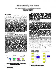
The design-level debugging approach for RTESS discussed in this paper is shown in Figure 1. Model Driven Development (MDD)
Requirements
Design level
Model-based Design Level Debugging
Model-based Target Debugger GUI [UML Sequence & Timing diagrams]
Design Model (MDD tool)
(Qt)
Code Generation
XML file
Debug Interface
(MDD tool)
System Code
Linker map file
(Platform Specific) Code level
AWK script
files .c .h
Deploy interface
Host side Target side
Real-Time Embedded System (Real-Time Operating System)
Target Monitor (C Language)
Figure 1. Model-based design-level debugging for embedded systems
A. Brief Overview The proposed model-based debugging technique comprises of a target debugger on the host side with a (software) target monitor solution on the target side as seen in Figure 1. Based on the requirement specification the design model is specified using UML diagrams (using any MDD tool [16]). The system code thus obtained (from automatic code generation using MDD tool) is deployed on the embedded system using a deploy interface as shown in Figure 1. Next, the target monitor is bundled with the given RTOS framework running on the target. The model-based, design level target debugger Graphical User Interface (GUI) on the host side receives back annotated trace data from the target monitor using a debug communication interface. The trace data provides details about the target behavior in real-time. The target debugger re-constructs the behavior of the target in realtime using UML interaction diagrams such as the sequence diagram and the timing diagram in the GUI. B. Prototype Based on the generic model-based debugging approach described above, a prototype is implemented and evaluated for various application scenarios. 1) Target monitor and RTOS framework In our prototype, the target monitor is implemented in the programming language “C. The RTOS framework used in our
prototype is the Real-Time Execution Framework (RXF) [12]. The target monitor is bundled along with the RTOS framework used. However, note that the proposed approach is independent of the RTOS framework under consideration (in the prototype). The RTOS framework used comprises of a scheduler that handles the events directly. The target monitor routine is invoked in the RTOS framework for consumed events. For example, when an event is processed and dispatched to its respective receiver, the target monitor is notified about the event consumption. Along with this notification, data pertaining to the event consumed such as the source, destination, event id, current time and the current state of the event receiver are sent to the respective Input/Output (I/O) routine of the target monitor. This I/O routine of the target monitor handles the trace data pertinent about the target behavior based on the chosen debug communication interface (between the target and the host computer). The target monitor uses a custom-defined frame format [4] to send these notifications about the target behavior to the host side. The notifications are sent to the host computer using a debug communication interface. A comparison of several debug interfaces for the proposed approach is discussed in [13].
three blocks as shown in Figure 2. Block (a) shows the classes, objects, states and attributes available in the embedded software running on the target system. Block (b) displays the sequence of events and the temporal behavior of the target using UML sequence diagrams with time stamps (sequence diagram tab) and UML timing diagrams (timing diagram tab). Block (c) displays the reconstructed messages on the host side (based on back-annotated data from target and the XML file). 4) Visualizing RTES behavior in real-time Our discussed approach can be used for debugging and visualizing the behavior of the embedded system as follows: •
On the host computer, the animation program in the target debugger GUI is started. The XML file generated for the corresponding project is loaded in the target debugger. A debug communication interface (for the communication between target and host) is chosen. The target debugger is now ready for receiving the trace data from the target.
•
Once the system code is deployed in the target, the target monitor (bundled with the RTOS framework, e.g. RXF) starts sending state, event and temporal information pertinent to the behavior of the target. This trace data is sent via the chosen debug communication interface to the host computer.
•
The animation program in the target debugger receives and decodes this trace information with the aid of the XML file. It reconstructs the target behavior on the host computer, at the design-level, using UML sequence diagrams with time stamps and timing diagrams. Thus, with the aid of this approach the target behavior can be visualized and debugged in real-time at the host computer.
Figure 2. Model-based target debugger GUI
2) Model Driven Development and system code Based on the requirements specification the embedded software (to be developed) is specified using UML diagrams (design model) in MDD tool [3]. The next step is the automatic code generation process in the MDD tool used [3], which generates the application specific system code. The system code thus obtained can now be executed on the target. During the compilation of the system code, an XML file is generated at the host side using an AWK script (which parses the linker map file, source and header files for a given project). The generated code is deployed on the embedded target using a deploy interface, such as the Keil Ulink [1] adapter. 3) Target Debugger GUI The target debugger is implemented in the User Interface (UI) framework, Qt [11]. The target debugger GUI consists of
Figure 3. Target debugger GUI–block (b): Sequence diagram with time stamp
The prototype implementation described above has been evaluated on embedded target platforms such as the MCB2140 and MCB1700 from [1] for a number of application scenarios [4]. Visualizing a simple “blinky” example (wherein LEDs are toggled between ON and OFF states) in the evaluation board using the target debugger approach is illustrated in this paper. Figure 3 and Figure 4 are screenshot(s) of target debugger displaying the UML sequence and timing diagrams respectively. These diagrams are displayed in block-(b) in target debugger GUI for the LED toggling example.
target monitor is handled via a custom-defined protocol. The protocol design is extensible, compact and requires minimum number of operations. For example, the minimum frame-size for the protocol is 2 bytes and an event-consumed notification requires 23 bytes of data. The frame format of this protocol is described in detail in [4]. • Figure 4. Target debugger GUI–block (b): UML timing diagram
IV.
DISCUSSION AND EVALUATION
A discussion based on the salient features introduced in the proposed approach is provided in section IV.A. These features eliminate the risks due to the change in program behavior before and/or after debugging the system code. An experimental evaluation of the performance metrics for the model-based debugging approach is provided in section IV.B. A. Salient features in the proposed approach Model-based debugging in the existing commercial MDD tools such as Rhapsody [2] involves extensive instrumentation of the source code. This incurs protocol and performance overhead during debugging. It could also result in modifying the temporal behavior of the embedded systems. In order to overcome the aforementioned limitations, the approach discussed in this paper employs the following aspects. Application‘s sources
B. Performance Metrics Performance metrics based on the measurements for the various application scenarios in an evaluation target system (MCB1700 [1]) is presented in this section. 1) Debug communication interface and target monitor size
A major factor influencing the real-time behavior of the embedded system is the communication overhead between the target system and the host computer (i.e. huge debug data being sent back and forth between the target and the host computer). In order to minimize this, an AWK script parses the source files, header files and linker map file (for a given project) and creates a symbol table at the host computer in our approach (Figure 5). This symbol table enables identifying each element in the system code such as class, instance, event, etc, by an ID. This symbol table data is stored in an intermediary format such as the XML file at the host computer. On receiving the trace data from the target, the target debugger decodes the trace data with the aid of this XML file. The trace data from the target is translated and the animation program in the target debugger GUI re-constructs the target behavior in the form of UML sequence and timing diagrams in real-time.
AWK Script
.c & .h files
TABLE I. Intermediate Format (XML file)
Target debugger
Application.map
Host side
Application‘s linker map file
EXPERIMENTAL SETUP
Evaluation board
MCB1700 [1]
Microcontroller family
Cortex-M3 (LPC1768)
Max. Clock frequency
100 MHz
RAM/ROM size
64 Kbyte/512 Kbyte
Target side Real‐Time Embedded target (Real‐Time Operating System)
•
•
Buffer
Target monitor
TABLE II.
Debug Interface
TARGET MONITOR SIZE FOR DEBUG INTERFACES
ROM
RAM
Total
(bytes)
(bytes)
(bytes)
Figure 5. XML file creation for target debugger at host computer
EIA-232
1061
135
1196
Dynamic source code instrumentation is eliminated with the introduction of an optimized monitoring software routine in the target monitor (implemented in the programming language ‘C’). The target monitor (library) is bundled with the RTOS used (RXF [12]). The target monitor is now independent of the application, its size, complexity and source code. The target monitor occupies approximately 1Kbyte of memory which is accommodative for small embedded platforms. Moreover, because of its size, the target monitor can be bundled along the final production code as well.
µVision
966
85
1051
Trace 32
1851
188
2039
In addition to the optimized target monitor size, the information exchange between the target debugger and the
The communication between the target monitor and the host computer takes place via a debug communication interface. For the proposed approach, the applicability of a generic EIA-232 (serial/UART) [14] interface and the industry standard JTAG-based (µVision [1] and Trace 32 [15]) debug interfaces are evaluated. The target monitor implementation varies for different debug interfaces mainly based on the APIs available for each interface and the functionality that it provides. It is also dependent on the features supported in the
respective microcontroller family for the given evaluation board. Detailed implementation specifics of target monitor for the aforementioned debug interfaces is discussed in [13]. The experimental setup for the measurements is shown in Table 1. The memory footprint (size) of the target monitor for the various debug interfaces is shown in Table 2. The target monitor size varies between 1Kbyte and 2Kbyte for the debug communication interfaces under consideration. This target monitor memory footprint is accommodative for small embedded target platforms. Moreover, the target monitor size is independent of the application used, its size and complexity. Thus the need for dynamic source code instrumentation for debugging is eliminated with this approach. 2) Event (bursts) handling Events consumed at a higher frequency in a short period of time by the target system can be termed as event bursts. Since the target monitor implementation depends on the debug interface used, the number of events (and event bursts) the target monitor can handle also depends significantly on the debug interface under consideration. However, in order to handle the event bursts the target monitor is implemented with a send/receive buffer interface (Figure 5). The applicability of the target monitor buffer and its dimensioning is again dependent on the debug interface used. TABLE III.
NUMBER OF EVENTS HANDLED PER INTERFACE
is a buffer overflow, the data in the ring buffer could be overwritten. This can lead to a loss of data (notifications about target behavior) stored in the monitor buffer. This is also because of the fact that the target monitor is assigned as a lower priority task and can access the system resources once they are freed by the higher priority (system) tasks. In this case, whenever the target monitor buffer is full, the target debugger is notified about the possible loss of data. In this scenario there are two possible configuration options, whereby the end-user has to compromise between target monitor buffer size and the influence on real-time characteristics of the embedded target. For instance, since the buffer size is configurable, it is up to the end-user to allocate a smaller/larger buffer size. As the target monitor implementation is dependent on the debug interface used, the buffer size and its usage is also dependent on the debug interface under consideration. On the other hand, the user could also assign the target monitor as a higher priority task. However, when the end-user gives a higher priority to the target monitor (and/or increases the buffer size), he has to compromise between the influence on the real-time characteristics and the loss of target-behavior data/notifications. 4) Time spent in the target monitor routine TABLE IV.
TIME SPENT IN TARGET MONITOR ROUTINE
Debug Interface
Time spent in monitor routine [µs]
556
EIA-232
50
µVision
3770
µVision
265
Trace 32
3268
Trace 32
7
Debug Interface
Events per second
EIA-232
The values shown in Table 3 provides a comparison of the number of events that each debug interface can handle theoretically before the use of target monitor send/receive buffers (in our prototype implementation). For example, for the EIA-232 interface, the theoretical maximum number of events that it can handle per second is 556 (115200 [baud rate] / 9 [8bit+stop bit] / 23 [number of bytes per event consumed notification]). However, when there is a burst mode in the target system (i.e., number of events per second higher than the theoretical estimation in table 3), this can be handled with the use of target monitor buffer. Handling of burst-mode data can also be taken over by the APIs provided by the debug interface used. Thus, when there is consistent burst of events, appropriate dimensioning of target monitor buffer size and/or selection of a debug interface by the end-user is necessary. 3) Target monitor buffer overflow and real-time characteristics of the embedded target In our prototype the target monitor is handled as a lower priority task in comparison with the system tasks. This implies that the target monitor is invoked during the “idle” state of the main loop of the RTOS framework. Let us consider a burst mode scenario, in which there is a possibility that the target monitor buffer overflows. The target monitor buffer is implemented as a ring buffer. This implies that whenever there
The target monitor routine sends notifications such as event consumed, new objects created/destroyed, answering to query about state, attribute, etc. Among these, the “event consumed” notification would be the most often used command. It also has the longest frame size of 19 bytes [4] in our custom-defined protocol format. The time spent in monitor routine per event consumed notification for the three debug interfaces is shown in table 4. This is measured using a logic analyzer. This time spent [in the order of µs) in the monitor routine is measured and known beforehand. This bounded delay can be included in the system design phase and accommodated in the design model by the end-user. Note that both the µVision and Trace32 are JTAG-based interfaces. However, the significant difference in the time spent in monitor routine for both µVision and Trace32 arise from the following reasoning. The µVision makes use of a polling mechanism to read/write data, whereas the Trace 32 has an internal buffer which takes care of reading/writing data (i.e., between the target monitor Input/Output routine and the µVision/Trace32 interface). 5) Traditional vs Proposed approach- Memory overhead The proposed approach has been evaluated for four example scenarios. Similarly, the existing model-based debugging feature in the MDD tool [3] was applied to the same
evaluation scenarios. Note that the four application scenarios consist of increasing system code (size) and complexity. For instance application scenarios 1, 2, and 3 consist of 2, 4 and 8 classes respectively (based on the “blinky” example described in Section II.B). Scenario 4 is based on a more sophisticated case study involving a MIDI system (15 classes). Detailed description of the MIDI system evaluation for the proposed approach is available in [4]. The complexity of the system also varies based on the number of events handled and dependencies on other modules.
of the application used, its size and complexity. As the temporal overhead is constant and known beforehand, the enduser has an opportunity to include this in the system design phase. Thus, the discussed methodology enables model-based debugging for small RTESS. Future work will concentrate on adding UML state chart diagrams in the target debugger GUI for visualizing the target behavior and evaluation on other target platforms.
The memory overhead incurred (in the embedded target) using both the approaches for the four scenarios (for modelbased debugging) are shown in Figure 6. From Figure 6, it is evident that the memory overhead increases with an increase in the application size using the model-based (live animation feature) approach in MDD tool such as Rhapsody [3]. On the other hand, the size (and the percentage increase) of the target monitor memory footprint is negligible in comparison with the increasing application size as seen in Figure 6 for our proposed approach.
This work was supported by a grant from BMWi-ZIM, DAAD and industrial partner Willert Software Tools GmbH. We would like to thank the project teammates at Willert Software Tools GmbH and Michael Spieker and Pablo Tecker from UAS-Osnabrueck for their cooperation. We also thank the four anonymous reviewers for their valuable comments and suggestions to improve the quality of the paper.
% Memory Overhead (in embedded target)
Memory overhead for existing vs proposed approach 350 300 250
MDD tool[Rhapsody]
ACKNOWLEDGMENT
REFERENCES [1] [2] [3] [4]
Proposed approach
200 150
[5]
100 50 0
[6] 1 2 3 4 Application Scenario (increasing size and complexity)
[7] Figure 6. Memory overhead (in embedded target) for model-based debugging of various application scenarios [8]
V.
CONCLUSION
Debugging RTESS is a challenging task in comparison with debugging the desktop systems. While there are some traditional and model-based tools for debugging RTESS, these have limitations. Model-based debugging techniques in the existing tools usually involve dynamic source code instrumentation. This instrumented code increases with the increase in the application size and necessitates sophisticated debug interfaces. All these factors make the existing modelbased debugging techniques unsuitable for the memory-size constrained RTESS. In order to overcome the aforementioned limitations, a model-based debugging methodology for small RTESS was outlined in this paper. Using the proposed methodology, RTESS behavior can be visualized in real-time using UML sequence and timing diagrams. Performance metrics based on measurements for various application scenarios in an evaluation target system were presented. The discussed methodology involves constant (static) and bounded overhead for both memory footprint and temporal delay. The overhead introduced is known (measured) beforehand and is independent
[9]
[10] [11] [12] [13]
[14] [15] [16] [17]
Embedded Development Tools, http://www.keil.com (May. 2011) Object Management Group, http://www.omg.org (May. 2011) IBM Rational Rhapsody Developer, version.7.5.1 http://www.ibm.com/software/awdtools/rhapsody/ (May. 2011). P. Iyenghar, C. Westerkamp, J. Wuebbelmann, E. Pulvermueller, A Model Based Approach for Debugging Embedded Systems in Real-time, in 10th ACM international conference on Embedded Software, EMSOFT 2010, ACM, New York, NY, USA, 69-78. G. Karsai, J. Sztipanovits, A. Ledeczi, and T. Bapty. Model-integrated development of embedded software. Proceedings of the IEEE, 91(1):145 – 164, Jan. 2003. C. Bunse, H.-G. Gross, and C. Peper. Applying a model-based approach for embedded system development. In 33rd EUROMICRO Conference on Software Engineering and Advanced Applications, pages 121 –128, Aug. 2007. T. Harmon and R. Klefstad. Interactive back-annotation of worst-case execution time analysis for Java microprocessors. In 13th IEEE International Conference on Embedded and Real-Time Computing Systems and Applications, RTCSA 2007., pages 209–216, Aug. 2007. Y. Jiao, K. Zhu, Q. Yu, and B. Wu. Towards Model-Driven Methodology: a Novel Testing Approach for Collaborative Embedded System Design. In 10th International Conference on Computer Supported Cooperative Work in Design, CSCWD ’06., pages 1 –5, May. 2006. BridgePoint UML Tool – Mentor Graphics, http://www.mentor.com/products/sm/model_development/bridgepoint/ (May. 2011) Enterprise Architect UML Tool – Sparx Systems, http://www.sparxsystems.com/ (May. 2011) User Inteface (UI) Framework-Qt, http://qt.nokia.com/ (May. 2011). Willert Software Tools GmbH. http://www.willert.de/ (May. 2011) P. Iyenghar, M. Spieker, P. Tecker, C. Westerkamp, J. Wuebbelmann, UML Target Animation: A Comparison of Debug Interfaces for Design Level Debugging, in System, Software, SoC and Silicon Debug Conference, S4D 2010, Sept. 2010. J. Axelson. Serial Port Complete: COM Ports, USB Virtual COM Ports, and Ports for Embedded Systems. Lakeview Research, 2007. TRACE-32 debug interface, http://www.lauterbach.com/ (May. 2011). Case tools for embedded systems, www4.in.tum.de/~schaetz/papers/TUMI-0903.pdf (May. 2011). Watterson, C., Heffernan, D.;, "Runtime verification and monitoring of embedded systems," Software, IET , vol.1, no.5, pp.172-179, Oct. 2007.


![[PDF] Download Software Engineering for Embedded Systems ...](https://m.moam.info/img/260x300/pdf-download-software-engineering-for-embedded-sys_6478a840097c474d228d655c.jpg)


