project, part of the. Terminal. Area Productivity. (TAP) program at NASA. Ames, addresses ... to the 'Final' controller for runway 18R. 4. The Final controller ...
MODEL-BASED DESIGN OF AIR TRAFFIC CONTROLLER-AUTOMATIONINTERACTION Stephan
Romahn
l, Todd NASA
J. Callantine
Ames Mail
Moffett [sromahn,
Field,
tcallantine,
ABSTRACT A model of controller and automation activities was used to design the controller-automation interactions necessary to implement a new terminal area air traffic management concept. The model was then used to design a controller interface that provides the requisite information and functionality. Using data from a preliminary study, the Crew Activity Tracking System (CATS) was used to help validate the model as a computational tool for describing controller performance. 1. INTRODUCTION Center-TRACON Autom ation System (CTAS) CTAS is an air trafficmanagement tool designed to improve the efficiency of descents, increase aircraft landing rates, and enhance the air traffic controller's ability to manage air traffic [5]. One component of CTAS, the Final Approach Spacing Tool (FAST), generates an approach sequence for all active runways of a given airport based on arrival route definitions specific to the particular terminal area. The approach sequence generated by FAST is displayed to the controllers to support their planning tasks. FAST is therefore a component of information management automation for controllers, while an aircraft's Flight Management System (FMS) is control automation for pilots [1]. TAP Program & CTAS/FMS Integration A CTAS/FMS integration project, part of the Terminal Area Productivity (TAP) program at NASA Ames, addresses extensions to the CTAS air traffic management concept--among them the harmonization of CTAS and FMS data bases and the use of advanced data link technology for integrating ground-based CTAS automation and airborne FMSs. Under one operational concept for CTAS/FMS integration, controllers issue charted FMS arrival clearances that are valid through the runway localizer 1 NRC-NASA
Ames Research
2 San Jose State University/NASA
Associate,
2, and
Research Stop CA
Everett
262-4 94035-1000,
USA
epalmer]@mail.arc.nasa.gov intercept. The arrivals can be modified by CTAS to adapt to the traffic situation. Pilots load these arrivals and their modifications into the aircraft's FMS. With the addition of data link technology, controllers can 'uplink' trajectories optimized for traffic sequencing and spacing directly to the aircraft's FMS. This could potentially decrease required communications and help realize advantages affordedby accurate and efficientFMS-guided flight in the terminal area. Model-based Implementation Approach For controllers and pilots to use this new functionality effectively, some modifications to existing ground-based and airborne equipment are anticipated. This paper focuses on the process of designing a prototype controller workstation, specifically, the Planview Graphical User Interface(PGUI) component of FAST. A model-based approach to design is employed that starts with a description of the operational scenario. Based on this description, a task analysis was performed that identifies and describes the Air Traffic Control (ATC) tasks involved at three levels of abstraction. At the lowest level, the task elements are allocated to the controller or to the automated system (i.e., FAST), respectively; the model also includes triggering and terminating conditions for each activity, and descriptions of the information necessary to support the controllers' decision-making processes. This task model, however, focuses on communication and system interaction tasks. The process of decision making itself is not modeled. The model was used to develop a prototype of the controller interface and a set of procedures to operate it. The actual design of the PGUI entails a number of additional issues beyond the scope of this paper; instead, the focus remains on the model-based design process. Preliminary simulation studies were conducted to evaluate the concept and the PGUI design. The model was also cast in a computational form for use with the Crew Activity Tracking System (CATS) [3, 4]. CATS used data collected during the preliminary studies to help
now with San Jose State University/NASA
Ames Research
Center
A. Palmer
Center
Ames
Research
Center
refineandvalidatethemodel'sdescription of controller performance, sothatit canbeusedto simulate controller activitiesin the futureas a meansfor evaluating the operational concept forairtrafficmanagement scenarios. 2. MODEL
OF TERMINAL AREA TASKS
CONTROLLER
Operational Scenario The operational scenario is based on flights into Dallas/Fort Worth International airport (DFW), specifically, flights arriving through the southwest feeder gate bound for runway 18R (Figure 1). An FMSequipped aircraft is used as an example, the scenario consists of the following sequence of events: 1.
2. 3. 4. 5.
6. 7.
The 'Feeder' controller accepts the handoff from the 'Center' controller figr Sector 62 (see Figure 1). The Feeder controller issues the FMS arrival clearance to the aircraft. The Feeder controller 'hands off' the flight to the 'Final' controller for runway 18R The Final controller accepts the handoff. If necessary, the Final controller modifies the FMS clearance (i.e., adjusts the location of the base turn to the final approachheading). The Final controller issues the approach clearance to the aircraft. The Final controller 'hands off' the aircraft to the Tower controller.
Additionally, if necessary, a controller can make speed adjustments to the FMS clearance, or revoke it altogether and 'vector' the flight (i.e., issue heading, altitude, and/or speed clearances)at any time during the arrival. This operational scenario provides the foundation for investigating operations in which controllers only issue clearances using voice communication, as well as combined voice-data link operations in which FMS trajectory data is exchanged digitally and other clearances are issued by voice.
Task Structure The description of the tasks of the Feeder West 2 controller and the Final controller for runway 18R are based on the above operational scenario. A three level task decomposition was deemed suitable for controller models. It affords a sufficiently detailed analysis of the tasks and information needs of the controllers to derive user interface requirements. Figure 2 depicts the top-level activities of the feeder controller. It provides a general description of the activity 'flow' for each arriving aircraft.
Monitor aircraft Assign arrival
Issue vectors Handoff aircraft
Figure 2. Top-level
description of feeder controller activities.
Lower-level task elements, however, can vary with different situations. Depending on aircraft equipment, or type of communication (e.g., voice or data link), tasks may or may not apply to a certain flight. Other tasks may be performed differently under certain conditions. Figure 3 illustrates these differences.It decomposes the high-level activity Assign FMS arrival in two ways. The left-hand side of the figure depicts a voice-only scenario, the right-hand side depicts a data link scenario. It is apparent that the tasks Receive UP1 (i.e., receive user preference information viadata link) and Formulate FMS clearance (for a pending uplink) are not performed in a voice-only scenario. Furthermore, the tasks lssue FMS clearance and Receive response are performed differently, depending on whether data link is used. This is taken into account at the model's lowest level; that is, talk to pilot and listen to pilot are replaced by controller actions performed via the PGUI. 3. CONTROLLER-AUTOMATION INTERACTION DESIGN
/ Figure 1. Operational scenario at DFW, showing Center, Feeder, and Final airspace sectors, and the nominal southwest arrival path.
Task Allocation Task elements must be allocated to either the controller or the FAST system. The primary design principle for determining the allocation takes into account the role of FAST as an advisory system: the ultimate decision about the course of action shall remain with the controller; and furthermore, the automation shall not obstruct any action by the controller (e.g., [7]). Accordingly, the generation of advisories concerning the runway allocation and the determination of the sequence number, including the generation of a corresponding FMS route, is allocated entirely to the automation. However, the controller always has the option to override (i.e., ignore) a suggestion from FAST. Whereas issuing
I
uuzlr
mlrle
A.Ig
....
way
_
I °'term" n..p.r ea*'nca
i
Freeze
runway
_r i
Oetermlnefor action
I
ISSUe
aircraft ]y
y
I
I
j
I
Ea,c,te ._e,.. easiqn_nway ,Nooac_ II
I-_t , _
De"in" "qo'nca' I i_.nt,fr.irc..ft I
_
Execute
free.
runway
PM_
ciwirin_
I
Assign,_.way
Delecl ASSESS notification message
z4enUfy
_ ._.
Execute
J
Freezerunway
k
I Determine act on for
| u
l
_
iO
I)110!
I
response
Listen
pilot
I
aircraft
I
to
assign
m_.cute..m
_1
BOCSiVO
Mark
Figure
3. Models
the
FMS
the in
controller, accordance
of the activity
clearance
accomplished
the
Identify
Assign
scenario;
is a task
that
FMS
the right-hand must
be
arrival.
The
side
shows
performed
composition of the data link to the FAST advisories
beforehand
_
• FMS
_ J _
I._(irmulm
1.
Task
activities denotes
that the Automation;
Identity
example,
left-hand how
Subtask Detect notification Assess message Determine runway Identify aircraft ldenttfy runway Execute assign runway Receive
Determine sequence Freeze runway
Determine appropriate action for FMS clearance Formulate FMS clearance Issue FMS clearance
Receive
response
Mark flight
#
I
j J
Gllarancll aircraft IINIIll_I
J I
aircraft
J
response
side prescribes
the activity
feedback
. Determine sequence # Idennfy aircraft Execute freeze runway Rccc_':c fccd_ac': Determine appropriate action for FMS clearance ldentifyaircraft
to
mes_uHe
I
aircraft
j
,d.ntiiy
Table
the activity
be performed
l describes FMS
indicate
activities
the
task
in
a
arrival
cases,
that
the
from
controller
be performed
data
link.
allocation data
FAST
FAST
should using
for the
link
can
perform;
may
choose
and perform
activity
scenario.
Italics
however, to
the task
in
override
differently.
FAST
override
(A
Allocation A A A&C A (default) C (override) A (default) C (override) A (default) C (override) C A&C A A
User
Interface
Specification
After appropriately allocating the prescribed tasks, the controllers' information needs and the necessary access to functions were extracted from the model for all tasks
that
with
respect
following design FAST
were
allocated to
the
to the Assign
determinations of the PGUI
were
to
the
incorporated
into
the
to benefit from the them, the runway
number must the controller
From prototype gather A A C
the
the
functionality:
The
specifications
task
user
subjective
PGUI feedback
sample data, a preliminary controllers used the simulated
traffic
scenario described traffic controllers
in several
interface
been must
assignment
user
interface
and
function
was
developed.
from
study PGUI
and
the
derived
allocation, In
users
and
a
order
to
collect
was conducted in which prototypes to control
situations.
previously, controlled
has
STUDY
for the
analysis
controller
be displayed must receive
a data link clearance has been received.
4. PRELIMINARY
from
example, task,
In order evaluate
the sequence In addition,
appropriate feedbackthat sent and which response Access
For
arrival
interface:
Displayed information: advisories and to
assignment and to the controller.
controller. FMS
allow the controller to override a runway to issue a data link FMS arrival clearance.
Compose messa_,e Identify aircraft Execute send message Receive feedback Detect notification Assess message ldentify aircraft Execute mark flight Receive feedback
how
should
Assign some
showing
controller may choose C denotes Controller).
Assign runway
I
°%.:,7:.Z%,:. ,
I _
by
message can be
by the automation.
allocation
Task Receive UPI
I
r.nw.y
rmo
Idlnti_ _,ompose
I ... ,.so,--nca I'
advisories Table
runway
__ll
flight
in a voice-only
_
I
feedblCk
Assess I
I y
aircraft
_
eppropr ate FMS c earsnce
clearance
IdeetI_
I _ IiIl
aircraft
....... , .....
"_
a
I Formulate
clearance
II
i De'ermine number s"_"*nca _------t Det"'"' a*_"ca '
Recllve Receive
_
L
i
RscaJvetee_Dack
j_--._4ugmrmlmm I
1
.....
"N_ 1
1
appropriate FMS clearance
FMS
.....
UPI
runway
Identlf_ I
ReCeive
For
the
operational
groups of two actual DFW arrival traffic in
air the
Feeder West 2 and runway respectively (see Figure 1).
18R Final
airspace
sectors,
Data Collection Several types of data were collected from the preliminary study, in addition to subjective controller opinions. Tools used in the CTAS development effortto simulate air traffic, route communications among CTAS components, etc.--and the PGUIs themselves--all produce data. Again owing to the scope of the paper, these data are described as consisting of three general types: State information: Data describing the evolving state of the controlled air traffic were collected from a variety of sources. Ofprirnary interest were time-stamped position and state data for each aircraft in the system, whether the aircraft was FMS-equipped or not, runway assignments, and the sequence number generated for each aircraft by FAST. Event logs: Data describing controller actions and cues appearing on the PGUI display were collected as time-stamped events. These data include feedback of actions a controller performs using the PGUI interface (e.g., when a controller issued a data link FMS clearance), actions performed by another controller registered on the PGUI display (e.g., an indication to the Final controller that the Feeder controller wishes to 'hand off" an aircraft), or when aircraft first appears on the PGUI. Communication transcripts: Voice communications that occurred between the controllers and pilots in the system (available from 'pseudo-aircraft' 'pilots' --another facet of NASA Ames' simulation support tools) were transcribed and coded to indicate who initiated the communication, to whom it was directed, and its contents. The next section examines how these three types of data were support of the model-based 5. ROLE
OF THE CREW SYSTEM
used as input design process. ACTIVITY (CATS)
to CATS
in
TRACKING
CATS was designed to supply, in real time, knowledge required by training and aiding systems, or enhanced displays [3]. More recent research exploited these same capabilities to use CATS as a post hoc analysis tool to support procedure refinement using simulator data [4]. For these applications, CATS takes input consisting of the current state of a controlled system, environmental constraints, and operator actions. It uses a normative model of operator activities to output (i) predictions about what activities the operator should currently be addressing, and (ii) interpretations of actual operator actions [cf. 6]. To predict activities; CATS first uses current system state and environmental constraint information to activate 'context specifiers' [2]. CATS interprets an operator action either as (i) matching a prediction, (ii) as supporting the use of an alternative (but valid) method, or (iii) as a potential error.
The present research seeks to use the CATS framework differently. In previous applications, CATS used a normative model validated by domain experts that prescribes correct activities that operators can undertake to meet system objectives and uses the model to predict and interpret operator actions. The present effortseeks to use the CATS framework to process data that includes valid operator actions to refine and validate the descriptive capabilities of the model. There are two main reasons to pursue such an application. First, a model that could be used simulate controller performance would be a valuable tool for conserving scarce and expensive human air traffic controller subjects while still providing insights on some key issues (e.g., the pace at which controllers might issue particular types of clearances given some volume, sequence, or spacing of arriving air traffic). Second, the pilot procedures analyzed by CATS (see [4]) were different from current-day operations, and therefore a source of confusion warranting analysis, the sequences of controller activities required here are wellentrenched-----only the information sources and means of executing the action are undergoing modification. The present application necessarily de-emphasizes portions of the CATS architecture crucial for performing the processing required in the previous flight deck applications. Taken as a whole, Figure 4 depicts the architecture used in previous applications; the grayed-out portions of Figure 4 indicate those elements that play little or no role in the present application. Part of the reason for this concerns the types of knowledge and corresponding data most salient in the flight deck versus the ATC domain. For example, the 'state' of the controlled system is in fact the combination of all states of the aircraftunder control. And, instead of a dynamic set of constraints similar to the clearances pilots must comply with, controller goals/constraints take the form of general limits on spacing and letters of agreement between controllers responsible for adjoining sectors. Descriptive Model of Air Traffic Controller Activities The manner in which the controller model itself bears on the operation of CATS hinges primarily on the representation of conditions for predicting or terminating an activity; that is, the model still represents correct activities under normal operating circumstances. However, previous CATS models relied on a memoryless specification of context based entirely on states to predict operator activities before they were performed. The controller models used here, on the other hand, frequently represent the context for performing an activity in terms of events (see [2]). Furthermore, the model form used here incorporates both predicting and terminating conditions, often for cognitive, perceptual or verbal activities (Table 2). Here "prediction" is used in a descriptive sense--the model predicts not that the activity will be performed at some point in the future, but at this particular time. Such an event-based representation makes sense for capturing interactions such as the flow of controller-pilot discourse.
//
System
Human Operators
_
I
I
-
I"1
i
L
[ to training
Figure 4. CATS Architecture,
showing
or aiding
system
some of the modifications
]
required
for the present
°.
Table 2. Controller
model (excerpt)
Task
Condition
Determine
prediction idle, a/c before freeze horizon
runway
Identify
aircraft
Identify Execute runway Receive
runway assign feedback
Determine sequence # Determine appropriate action for FMS clearance Identify Execute Receive
aircraft send message feedback
Condition for termination
for
runway determined aircraft identified
runway mismatch betw, C and A aircraft identified runway
identified
runway runway
runway
assi_;ned
feedback
runway, aircraft aircraft
determined equipped., location ok,
seq. # determined action determined
traffic
situation
Detect
notification
Assess
message
response
sent received detec_d
recved
ok,
a/c not in target state action determined aircraft identified message response
identified assigned
two models: one for the Feeder controller and one for the Final controller, as shown by the 'stacked' model in Figure 4. Furthermore, CATS tracks the progress of each controller with respect to each aircraft in the system, and in certain situations (e.g., an aircraft handoff) an event may activate context specifiers that predicts activities in both models. Therefore, if the Feeder controller initiates the handoffof an aircraft, the event activates a context specifier that is broadcast to both models; in addition, the context specifierremembers that it has been activated for that particular aircraft, and will only activate once, even if the aircraft remains in a suitable handoff condition for a period of time.
aircraft message feedback response response
Table 3. Context
identified sent reeved detected assessed
As shown in Table 2, the controller model still uses logical equations of context specifiers to represent the conditions for predicting and terminating activities. Likewise, CATS still identifies activities to predict (and, in this case, terminate) by locating those with 'active' context specifiers. However, more focus is placed on the context specifiers for three reasons. First, event-based specifiers must retain the memory of their activation, something that was unnecessary in previous CATS applications; this is shown by the 'stacked' context specifier list in Figure 4. Second, observable details about controller actions are actually part of the set of events that are used to activate the context specifiers (Table 3). The third and final reason concerns a larger issue, viz., CATS is now tracking a distributed system. Up till now, the paper has referred to the controller model in the singular, but the CATS implementation actually uses
Context specifier a/e before freeze horizon
specifiers
(excerpt)
Definition
Data:
sqrt( (x-g)(x-g)+ (y-h)(y-h)) > i
x,y: a/c state freeze
Source
horizon
(g,h), tolerance (i): scenario file
runway aircraft
determined identified
not observable
runway
identified
runway
assigned
runway entered scratchpad key pressed
feedback
received
aircraft cursor
not
5. RESULTS
selected device
with into
callsign:
event-log
runway:
event-log
rw assignment: event log
observable
AND
DISCUSSION
The model-based design process described in this paper has been used to create a prototype user interface for an ATC application. This process helped to identify the information needed for the controllers to perform the tasks within the scope of the model. It also helped to develop the procedures for operation. However, it does
Event logs bycontroller, individual aircraft _
,
CATS Interface [_ [1
_11
State Data
II
_xxxx-
IIt_.
.................
Illll
_.._
II
III_I_IF
] [......._ [.----II Controller
II
Terminatedby CATS, shown by controller, time, or location
Mo,:t_ls
II
_
Log of Activities Predicted or
II
_t___&___
Event[
II! I, Ill [" 13:48:26
f
Voice communication
,/13:48:26
I from DAL1706 to Feeder: I Initial contact at FEVER
/
I 13:48:30
/
Voice communication
I from Feeder to DALI706: _.leared for FMS arrival
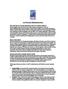
Figure
J
_
_3:48:30 _ FEVER
CATS predicts:
Feeder sends message/talks to DAL1706 [issue FMS Arrival clearance]
Feeder
CATS determines: issues FMS clearance
to DAL1706
5. Depiction of elements of the CATS interface showing output of task predictions from the event sequence (left) on the map of the terminal airspace
not--and is not expected to--help to define details of the user interface implementation, i.e. how information is being displayed. [3] A CATS model of the controller tasks is currently being used to analyze data collected in an initial study. Figure 5 depicts the CATS interface during the interpretation of the event data. This configuration--which is only one of many--allows a comparison of CATS' task prediction against the actual course of controller actions. Predicted and identified tasks are presented in relation to the current aircraft position. The results of the CATS analysis will later be used to refine the task model.
[4]
[5] 6. OUTLOOK After the analysis of the data from the initial studies is completed a revised set of user interface specifications will be compiled. Data from continuing studies, conducted as the interface design evolves, will be similarly analyzed using CATS.
[6]
[7] 7. REFERENCES [1] Billings, C. E. (1996). Aviation automation: The search for a human-centered approach. Hillsdale, NJ: Erlbaum. [2] Callantine, T. J. (1998). Cont_t in models of humanmachine systems. Proc_xlings of the 7th
(right)
IFAC/"IFIP/IFORS/IEA Symposium on Analksis, Design and Evaluation of Man-Machine Systems, Kyoto, Japm Callmtine, T. J., Mitchell, C. M, and Palma-, E. A. (1998). GT-CATS: Tracking pilot mode usage activities in the glass cockpit. International Journal of Aviation Psychology, submitted _r publication. Callmtine, T. J., Palmer, E. A., and Smith, N. (1997). Model-based crew activity tracking lbr precision descaat procedure refinerneat. Proc_.dings of the 1997 IEEE Confo'ence on Systems, Man, and Cybernetics, Orlando, FL. Erzberger, H., and Nedell., W. (1988). Design of automation tools for management of descent traffic. NASA Technical Memorandum. Moffett Field, CA: NASA Ames Research Center. Romahn, S., & Schafer, D. (1995). Automated classification of pilot errors in flight management operations. Proceedings of the 6th IFAC/IFIP/IFORS/IEA Symposium on Analysis, Design and Evaluation of Man-Machine Systems, Boston. Sheridan, T.B. (1988). Task Allocation and Supervisory Control. In Handbook of Human Computer Interaction.. M. Helander (Ed.). Amsterdam: Elsevier.