Second International Symposium on Engineering Systems MIT, Cambridge, Massachusetts, June 15-17, 2009
Model-Based Design Structure Matrix: Deriving a DSM from an Object-Process Model Amira Sharon1 , Dov Dori2 Technion – Israel Institute of Technology, Haifa, 3200, Israel Olivier de Weck3 Massachusetts Institute of Technology, Cambridge, MA 02139, USA Copyright © 2009 by Amira Sharon, Dov Dori, and Olivier de Weck. Published and used by MIT ESD and CESUN with permission. Abstract We investigate potential benefits of employing Design Structure Matrix (DSM) in the context of Model-Based Systems Engineering (MBSE) for the purposes of analyzing and improving the design of a product-project ensemble. Focusing on process DSM, we present an algorithm for bidirectional transformation frame between a product-project system model and its corresponding Model-Based DSM (MDSM). Using Object-Process Methodology (OPM) as the underlying modeling language, we examine and characterize useful and insightful relationships between the system model and its MDSM. An unmanned aerial vehicle case study demonstrates the semantics of and analogy between various types of relationships as they are reflected in both the OPM system model and the MDSM derived from it. Finally, we conclude with further research direction on showing how clustering of DSM processes can be reflected back as an improvement of the OPM model.
Key words Engineering systems, systems engineering, systems engineering management, project management, Design Structure Matrix, Model Based Systems Engineering, Project-Product Lifecycle Management.
1. Introduction Design Structure Matrix (DSM) is an accepted method for enhancing and analyzing design of products and systems. The use of matrices in system modeling can be traced back to Warfield in the 70's and Steward (1981). In the 1990s the method received attention and wide spread. Eppinger et al. (1994) used a matrix representation to capture both the sequence of and the technical relationships among design tasks, which was then analyzed in order to find 1
Ph.D. candidate, Faculty of Industrial Engineering and Management,
[email protected] Professor, Faculty of Industrial Engineering and Management,
[email protected] 3 Professor, Engineering Systems Division,
[email protected] 2
1
alternative sequences and/or definitions of the tasks. Eppinger (2001) also used DSM in the context of project management. Graphs have been used for system modeling since the early 1970's. For example, Eppinger at al. (1997) used signal flow graphs as a flexible tool for design process modeling. Kalligeros, de Weck O., et al. have used a Sensitivity DSM for platform identification. An elaborate example of a 50×50 DSM related to an automobile's engine compartment design appears in Ulrich and Eppinger (2008, p. 358). Traditionally, the system graph has been constructed by allowing a node to be one of two types of system elements: either an object (or a part, or a component), when the structure or the system was modeled, or a process (or an activity, or a task), when the work of constructing the system was considered, as in a work breakdown structure (WBS) or a critical path method (CPM) graph of a project model, or a specification of the dynamics of the product itself after it has been designed, manufactured, and delivered. Based on this observation, system-describing graphs can be categorized into two types based on the type of element represented by the node in the graph: object-based system graphs and process-based system graphs. Recent years have witnessed the emergence of models as a basis for synthesis, communication, development, and analysis of existing and new systems and product. Indeed, model-based systems engineering (MBSE) is a rapidly growing field of research and application. However, relationships between a model and a corresponding DSM of the same system have not been thoroughly investigated. This paper looks into the relationships between a system model and its DSM and features that can be studied by examining these relationships. The modeling language we use is Object-Process Methodology (Dori, 2002). OPM is a formal yet intuitive paradigm for systems architecting, engineering, development, lifecycle support, and evolution. It has been used for modeling complex systems, both natural and artificial, where artificial ones might comprise humans, physical objects, hardware, software, regulations, and information. As its name suggests, the two basic building blocks in OPM are (stateful) objects (i.e. things that exist, at some state), and processes (i.e. things that transform objects by creating or destroying them, or by changing their state. In this paper we do not relate to states explicitly. However, any stateful object with k states can be modeled as k distinct stateless objects. For example, Water with the three states cold, warm, and hot can be modeled as the three objects Cold Water, Warm Water, and Hot Water. 2. Object-Process-Based Systems Graphs and Their DSM Browning (2001) has suggested four different types of DSM according to the data that the DSM represents: (1) Component-based DSM, for representing relations among components, which are objects in the system, for use in systems engineering and architecting, (2) taskbased DSM, for representing relations among tasks or activities, which are processes in the system, for use in project management, (3) parameter-based DSM, which is similar to (2) but at a lower level, and (4) team-based DSM, for interfacing between teams, for use in organizational design and multi-team projects. The component-based DSM is the DSM of our object-based systems graph, while the task-
2
based DSM is the DSM of our process-based systems graph. Team-based DSM can be extracted from the agent links in an OPM model of a system-delivering project, as explained and demonstrated in the sequel. As we show next, a DSM that combines both component- and task-based DSM can be extracted from an OPM model. In an OPD in general, nodes can be of either type, namely both objects and processes, provided that the procedural links among them (which must be directed) are such that the resulting graph is bi-partite, i.e., any procedural link whose source is an object has a process as its destination and vice versa. Figure 1 is an OPD which demonstrates that it is a bi-partite graph. Like all the OPDs in this paper, it was drawn using OPCAT (Dori et al. 2003). This OPD uses only two OPM procedural links: consumption link and result link. Both have the same graphic symbol, but a consumption link originates from an object and terminates with a process with the semantics that the process consumes the object, while a result link originates from a process and terminates with an object, with the semantics that the process creates (yields) the object. The natural language text (ObjectProcess Language, OPL) in Figure 1, which was automatically generated by OPCAT, explicates the semantics of these two links. For example, the OPL sentence "P2 consumes B3 and B1." indicates that both B1 and B3 are linked to P2 with a consumption link, and the sentence "P3 yields B3 and B6." indicates that both B3 and B6 are linked to P3 with a result link. P1 yields B2 and B1. P2 consumes B3 and B1. P2 yields B4. P3 consumes B5. P3 yields B3 and B6. P4 consumes B2. P4 yields B3. P5 consumes B4. P5 yields B5. P6 consumes B6.
Figure 1. An OPD describing an Object-Process-Based Systems Graph (left) and its automatically-generated OPL paragraph
The OPD in Figure 1 contains one loop: {P2, B4, P5, B5, P3, B3}. As expected, the type of node in the loop keeps alternating between P (process) and B (object). Moreover, due to the fact that the graph is bi-partite, the number of nodes of the two types must be equal (three objects and three processes in our case) and the length of the loop is therefore an even number which is twice the number of objects (and processes). Figure 2 is the DSM of the OPD in Figure 1, where C and R respectively denote a consumption link, from object to process, and a result link, from process to object. To see the pattern of the loop {P2, B4, P5, B5, P3, B3} in the OPD, in Figure 3 we have rearranged the rows and columns of the DSM in Figure 2 to have P2, B4, P5, B5, and P3 arranged in a RCRCR sequence, and obtained an interesting pattern of alternating R's and C's right above the DSM diagonal, which was originally grey, with the DSM cell (B3, P2) completing the loop as the apex of an isosceles triangle whose base is the five-cell RCRCR string. Moreover, the grey cells of the displaced DSM rows and columns, which were originally along the
3
diagonal, are now arranged in a row beneath this "triangle". to
P1 B1 P2 B2 P3 B3 P4 B4 P5 B5 P6 B6 From
P1 B1 P2 B2 P3 B3 P4 B4 P5 B5 P6 B6
R
R C R C R
R
C R C R C C
Figure 2. The DSM that represents the graph and OPL paragraph of the OPD in Figure 1
to
P1 B1 P2 B4 P5 B5 P3 B3 B2 P4 P6 B6 From
P1 B1 P2 B4 P5 B5 P3 B3 B2 P4 P6 B6
R
R C R C R C R
R
C C R C
Figure 3. The Design Structure Matrix that represents the graph and OPL text of Figure 1 with rows and columns rearranged to visualize the loop {P2, B4, P5, B5, P3, B3}
3. Project-Product System Graphs and Their DSM Project planning and control are the essentials of project management. Focusing on productdelivering projects, the first step in project planning requires basic knowledge of the concept of the product that the project is expected to deliver. Project planning and control is an iterative process of derivation, refinement, and simulation of the product model, while maintaining traceability and coherence between the product model and the project plan at all levels. Therefore, the initial project plan, scope of work, Work Breakdown Structure, and 4
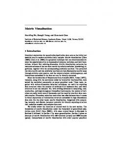
allocation of resources rely on understanding of at least the top-level product functionality, architecture, and concept of operation. As a case in point, we consider a project of developing an Unmanned Aerial Vehicle (UAV), by an imaginary New Millennium Aerospace (NMA) Inc., a government-contracted leading UAVs manufacturer (de Weck, 2008). A rough specification and sketch of the UAV “pusher” vehicle concept is shown in Figure 4. The payload is provided by the government as modified government furnished equipment (GFE), while the engine is supplied by an established commercial company (ECC) under a subcontract.
Figure 4. A rough specification and sketch of the UAV “pusher” vehicle concept
The first phase of the project includes identifying the project plan, addressing the project's major activities and their order of execution. We approach creating the initial project plan using the Project-Product Lifecycle Management (PPLM) framework (Sharon et al., 2008; 2009). Using this approach, the model ultimately contains the activities and tasks, which are OPM processes at various detail levels that are required for completing the product, the artifacts—informatical objects, which are mostly model-based documents, and the different resources. Having all this information embedded consistently in the same PPLM model eventually yields all the specific structural relations (among objects) and procedural relations (between objects and processes). The project planner can model the rationale for ordering the processes by identifying the flow of objects into and out of each process. Understanding the product objects' hierarchy hand-in-hand with the project tasks and progress provides the rationale for the technological process order and timing. 3.A. The OPM Based Project-Product Plan While there is no single "correct" OPM model, the model has to comply with the following basic requirements: • The model shall contain all the information provided in the text. • The model shall follow guidelines of the methodology part of OPM, including: o Starting with a top-level process at the System Diagram (SD, top-level OPD) of the model, representing the system's function, which in our case is the entire project. o Decomposing the system hierarchically using OPM refinement mechanisms, primarily in-zooming.
5
•
o Following the top-to-bottom ordering of a sequence of sub-processes within an in-zoomed process. The model shall include all the OPM things (objects and processes) needed for a complete representation of the project and the product.
The System Diagram (SD), the top-level view of the OPM model, is presented in Figure 5. The equivalent, automatically generated natural language text, called Object Process Language (OPL) paragraph, is listed in Figure 6. The top level process at the first System Diagram (SD) of the model, UAV Prototype Developing, represents the entire project. At each detail level, the OPD is constructed beginning at the top of the in-zoomed process and continuing downward, following the process execution order. Objects in the model are classified into three categories: human resources (OPM agents), facilities (OPM instruments) and deliverables (OPM outputs). The deliverables are informatical objects such as documents, approvals, simulations, analysis, specifications, and reports. Each deliverable results explicitly from a specific process and is used in a subsequent process. A deliverable is typically an instrument, since it is informatical and therefore not consumed by the process it enables. Some deliverables are product components, which specific processes generate. The leaf-level process names include a parenthesized task ID followed by duration in working days. The related object names follow a similar pattern, containing their source process, also in parentheses. This convention is useful for tracking inexplicit relationships among leaf-level elements.
Figure 5. OPD of the top-level System Diagram (SD) of UAV Prototype Developing
Figures 7 through 10 present two third-level OPDs in the model. The Definition process (SD1.2) is shown in Figure 9 and Figure 10, whereas the Avionics Development (SD1.1) is shown in Figure 7 and Figure 8.
6
Since the project plan model is constructed hierarchically, in accordance with OPM guidelines, we can rely on its consistency. Nevertheless, capturing the relationships between the leaf-level processes are the actual project tasks, activities or even work packages. The upper-level processes serve as logical clusters. Each such cluster is a node (OPD) in the model decomposition. Since we are interested in analyzing the relationships among leaf-level processes, and these are typically scattered over several OPDs, the project's DSM can be instrumental in explicating these relationships. New Millennium Aerospace (NMA) Inc. is physical. New Millennium Aerospace (NMA) Inc. exhibits UAV “pusher” vehicle and Integration and Testing. UAV “pusher” vehicle is physical. UAV “pusher” vehicle consists of Prototype UAV. Prototype UAV is physical. Prototype UAV consists of GFE Payload (product of j) and Engine (product of n). GFE Payload (product of j) is physical. GFE Payload (product of j) exhibits Payload Specification (product of d). Engine (product of n) is physical. Engine (product of n) exhibits Engine Specification (product of c). New Millennium Aerospace (NMA) Inc. consists of NMA’s Facilities Set and NMA's Human Resources Set. NMA's Human Resources Set handles UAV Prototype Developing. ECC is environmental and physical. ECC consists of Engine (product of n) and ECC Human Resources Set. ECC Human Resources Set handles UAV Prototype Developing. Government is environmental and physical. Government consists of GFE Payload (product of j) and Government Human Resources Set. Government Human Resources Set handles UAV Prototype Developing. UAV Prototype Developing requires NMA’s Facilities Set. UAV Prototype Developing affects GFE Payload (product of j), Engine (product of n), New Millennium Aerospace (NMA) Inc., Engine Specification (product of c), and Payload Specification (product of d). UAV Prototype Developing yields Prototype UAV.
Figure 6. The automatically-generated OPL paragraph of the OPD in Figure 5
Figure 7. OPD of SD1.1 - Avionics Development in-zoomed
7
3.B. Constructing the Model-Based DSM Based on the OPM model, we construct a 7×7 DSM, shown in Figure 11, for the leaf-level processes. It includes the first seven leaf-level project tasks a through g (including the dummy task “start”). DSM[i, j] = X means that task i requires an informatical object (deliverable or artifact) or physical object (part or assembly) from task j. All the entries in the matrix are below diagonal. This means that there are no iterations present in this project plan. In other words, downstream tasks depend only on upstream tasks and not on tasks that are further downstream. New Millennium Aerospace (NMA) Inc. is physical. New Millennium Aerospace (NMA) Inc. consists of NMA’s Facilities Set and NMA's Human Resources Set. NMA's Human Resources Set handles Avionics Development. Avionics Development requires NMA’s Facilities Set. Avionics Development affects New Millennium Aerospace (NMA) Inc.. Avionics Development zooms into Avionics design initiation (f,15) and Avionics delivery and checkout (p,12), as well as GFE Avionics Design (product of f). Avionics design initiation (f,15) requires Payload Specification (product of d), Engine Specification (product of c), and Requirements Document (product of b). Avionics design initiation (f,15) yields GFE Avionics Design (product of f). Avionics delivery and checkout (p,12) requires GFE Avionics Design (product of f). Avionics delivery and checkout (p,12) yields Avionics approval (product of p).
Figure 8. The automatically-generated OPL paragraph of the OPD in Figure 7
Figure 9. OPD of SD1.2 - Definition in-zoomed
8
The Project Activities DSM can be automatically extracted from the OPM-based project plan. All leaf-level processes are included in the first row and first column, as well as the triangle, as shown in Figure11. The upper level processes, above the leaf-level ones, will be addresses as "clusters" for further discussion. The relationship of task B being dependant on task A is evident from SD1.2 (Figure 9) where Project Start (a,0) invokes Requirements Definition (b,10) since it is the first process to be executed under Definition "cluster". New Millennium Aerospace (NMA) Inc. is physical. New Millennium Aerospace (NMA) Inc. consists of NMA’s Facilities Set and NMA's Human Resources Set. NMA's Human Resources Set consists of SW Team, AM Team, and SE Team. SW Team handles Software Specification Writing (g,12). AM Team handles Vehicle layout Determination (e,8). SE Team handles requirements definition (b,10). ECC is environmental and physical. ECC consists of Engine (product of n) and ECC Human Resources Set. Engine (product of n) is physical. Engine (product of n) exhibits Engine Specification (product of c). ECC Human Resources Set handles Engine Specification Negotiation (c,5). Government is environmental and physical. Government consists of GFE Payload (product of j) and Government Human Resources Set. GFE Payload (product of j) is physical. GFE Payload (product of j) exhibits Payload Specification (product of d). Government Human Resources Set handles Payload Specification Definition (d,5). Project Start (a,0) invokes Definition. Definition affects New Millennium Aerospace (NMA) Inc.. Definition zooms into requirements definition (b,10), Vehicle layout Determination (e,8), Software Specification Writing (g,12), Payload Specification Definition (d,5), and Engine Specification Negotiation (c,5), as well as Requirement Document Approval. requirements definition (b,10) yields Requirement Document Approval and Requirements Document (product of b). Vehicle layout Determination (e,8) requires Requirement Document Approval. Vehicle layout Determination (e,8) yields Vehicle Layout (product of e). Software Specification Writing (g,12) requires Requirement Document Approval. Software Specification Writing (g,12) yields Software Specification (product of g). Payload Specification Definition (d,5) requires Requirement Document Approval. Payload Specification Definition (d,5) yields Payload Specification (product of d). Engine Specification Negotiation (c,5) requires Requirement Document Approval. Engine Specification Negotiation (c,5) yields Engine Specification (product of c).
Figure 10. The automatically-generated OPL paragraph of the OPD in Figure 9
Depends on task (to) Task (from)
a
b
c
d
e
f
g
Project Start - a Requirements Definition - b
X
Engine Specification Negotiation - c
X
Payload Specification Definition - d
X
Vehicle Layout Determination - e
X
Avionics Design Initiation - f Software Specification Writing - g
X X X X
Figure 11. The Project Plan Activities DSM
9
The dependency of tasks C, D, E, and G on task B is also discerned from SD1.2, where all first require the Requirement Document Approval, which is the output of Requirements Definition (b,10). The dependency of task F on task B is not explicit in any single OPD, as there is no OPD in which both F and B are explicitly linked. Here we make use of the convention of including the object's source process (in parentheses). Indeed, in Figure 7 (SD1.1) we observe that Requirements Document (Product of b) is required for the Avionics Design Initiation (f,15), implying that task F depends on task B. In a similar manner we find the dependency of task F on task C and task D. Both can be concluded from SD1.1 thanks to the naming convention.
3.C Constructing the Model-based DSM Since the DSM is derived from the project-product OPM model, we can glean additional knowledge about task dependencies represented in the DSM and upgrade it to a Model-based DSM (MDSM). We distinguish three types of dependencies: D – Definition (of a document, design, specification, etc.), M – Milestone that coincides with obtaining an approval of a requirements or design document, a prototype, etc., and C – Component. X is left as is whenever a process is invoked by another process with no intermediate object. Starting with the DSM in Figure 11 and replacing where possible X's by D, A, or C and the names of the intermediary objects, we derive the MDSM in Figure 12. For example, "M Req. Doc. Approval" is inserted in the cell (4, 2) of the MDSM because, as shown in Figure 9, the informatical object Requirements Document Approval is the node of type object in the bipartite graph underlying the OPM model, which connects the process Requirements Definition to the process Payload Specification Definition. This MDSM does not include any C's, since it contains only the first seven tasks in the project, therefore no components are delivered yet.
Figure 12. The Project Plan Activities MDSM
10
Examining the dependency types enables us to gain deeper understanding of the way project processes depend on each other via objects and identifying critical objects. For example, a quick look at the MDSM reveals that Requirements Document Approval is a critical milestone, as it precedes and is a prerequisite for four of the six actual tasks. 4. Conclusion and Future Work We have laid down the principles of a Model-based DSM (MDSM) that is derived from an OPM model and shown potential benefits of studying it. We plan to pursue at least some of the following research topics. 1. Devise an algorithm for automatically (or semi-automatically) constructing the MDSM directly from a project-product OPM model, possibly directly from its OPL text. 2. Investigate the relationships between the project-product OPM model, the derived MDSM, and the project's task critical path derived by the Critical Path Method. 3. Investigate the relationships between the MDSM as defined above, which is process (task) based and the a new type of MDSM, called OPDSM, whose rows and columns are alternating objects and processes (as in Figure 2) and whose cells are the OPM procedural links (agent, instrument, consumption, result…). 4. Find ways to detect accidental unwanted loops in the OPM model by inspecting the corresponding MDSM and OPDSM (as in Figure 3). 5. Derive a team-based DSM from the OPM model using agent links. 6. Revisit and possibly improve task aggregation into interim-level processes in the OPM model based on manipulating the MDSM for better task clustering and/or loop eliminating.
References [1] Browning, T. Applying the Design Structure Matrix to System Decomposition and Integration problems: A Review and New Directions. IEEE Transactions on Engineering Management, Vol. 48, No. 3, pp. 292-306, 2001. [2] de Weck, O. MIT ESD.36 System Project Management course assignment, 2008. [3] Dori, D. Object-Process Methodology: A Holistic Systems Paradigm. Springer, Berlin, 2002. [4] Dori, D., Reinhartz-Berger, I., and Sturm, A. Developing complex systems with Object-Process Methodology using OPCAT. Lecture Notes in Computer Science 2813, pp. 570-572. Berlin/Heidelberg: Springer, 2003. [5] Eppinger, S.D., Innovation at the Speed of Information. Harvard Business Review, Vol. 79 No. 1, pp. 149158, 2001. [6] Eppinger, S.D., Nukala, M.V., and Whitney, D.E. Generalized Models of Design Iteration Using Signal Flow Graphs. Research in Engineering Design, Vol. 9 No. 2, pp. 1122-123, 1997. [7] Eppinger, S. D., Whitney, D.E., Smith, R.P., and Gebala, D.A. A Model-based Method for Organizing Tasks in Product Development. Research in Engineering Design, Vol. 6 No. 1, pp. 1-13, 1994. [8] Kalligeros K., de Weck, O., de Neufville R., and Luckins A., Platform Identification using Design Structure Matrices. Proc. Sixteenth Annual International Symposium of the International Council on Systems Engineering (INCOSE), Orlando, Florida, 2006. [9] Perelman, V., Sharon, A., and Dori, D. Towards a Unified Product and Project Lifecycle Model (PPLM) for Systems Engineering. Proc. 9th ASME Engineering Systems Design and Analysis Conference, Haifa, Israel, 2008. [10] Pimmler, T.U. and Eppinger, S.D. Integration Analysis of Product Decompositions. Proc. ASME Design Theory and Methodology Conference, Minneapolis, MN, 1994. [11] Sharon, A., de Weck O., and Dori D. Is there a Complete Project Plan? A Model-Based Project Planning Approach. Proc. Nineteenth Annual International Symposium of the International Council on Systems Engineering (INCOSE), Singapore, 2009.
11
[12] Sharon, A., Perelman V., and Dori, D. A Project-Product Lifecycle Management Approach for Improved Systems Engineering Practices. Proc. Eighteenth Annual International Symposium of the International Council on Systems Engineering (INCOSE), Utrecht, the Netherlands, 2008. [13] Steward, D.V. Systems Analysis and Management: Structure, Strategy, and Design. Petrocelli Books, New York, NY, 1981. [14] Ulrich, K.T. and Eppinger, S.D. Product Design and Development, Fourth Edition. McGraw-Hill, New York, 2008.
12