Model-Based Development of Web Applications. Using Graphical Reaction Rules. Reiko Heckel and Marc Lohmann. Faculty of Computer Science, Electrical ...
Model-Based Development of Web Applications Using Graphical Reaction Rules Reiko Heckel and Marc Lohmann Faculty of Computer Science, Electrical Engineering and Mathematics University of Paderborn D–33098 Paderborn, Germany {reiko,mlohmann}@upb.de
Abstract. The OMG’s Model-Driven Architecture focusses on the evolution and integration of applications across heterogeneous middleware platforms. Presently available instances of this idea are mostly limited to static models. We propose a model-driven approach to the development of web-enabled applications, seen as reactive information systems on an HTTP-based communication platform, which covers both static and dynamic aspects. To support the separate change of both platform and functionality we separate at model and implementation level the platform-independent application logic from classes specific to technologies like HTML or SOAP. We discuss a notion of consistency between models at different abstraction levels based on a concept of graphical reaction rules, i.e., graph transformation rules which integrate data state transformation and reactive behavior.
1
Introduction
Most business applications developed today depend on a specific middleware platform providing services for communication, persistence, security, etc. while supporting interoperability across different kinds of hardware and operating systems. If such systems have to interact over the web, for example to provide integrated services, we face the problem of the interoperability of these platforms. Solutions at different levels have been proposed to overcome this problem. At implementation level, the approach of web services provides a collection of languages and protocols to support interoperability at the level of text-based HTTP by interchanging XML-documents representing, e.g., remote procedure calls. At the level of design, the OMG has proposed the Model-Driven Architecture (MDA) [16,17] to achieve interoperability through models. Starting from standard UML models [12] specifying the intended functionality, the MDA approach is largely concerned with the vertical structure of the mappings required to implement this functionality on any given platform. The idea is to distinguish between platform-independent models (PIMs) that are refined into platformspecific models (PSMs) which carry all relevant annotations for the generation of platform-specific code. M. Pezz` e (Ed.): FASE 2003, LNCS 2621, pp. 170–183, 2003. c Springer-Verlag Berlin Heidelberg 2003 �
Model-Based Development of Web Applications
171
The idea seems realistic (and has in part been implemented) for mappings to data type or interface definition languages like SQL DDL, XML Schemata, or CORBA IDL, and for static aspects of Java and EJB, thanks to the relative simplicity and stability of these more mature languages. Siegel [15], for example, describes the use MDA for applications based on web services, focussing on the integration of service interfaces in applications developed with the MDA approach. However, the integration does not take into account dynamic information about how the services should be used. For behavioral models like statecharts and collaboration diagrams, transformations to code are more sophisticated, but largely platform-independent [3,5]. If we want to use such diagrams to model the business logic of our application, an integration with the platform-specific models and their mappings is required. According to the OMG’s proposal this integration should be done by augmenting, throughout the platform-independent models, model elements with annotations in terms of stereotypes and tagged values. Then, in the likely case of a change in the platform-independent model (induced, for example, by an evolution of the functional requirements), the platform-specific annotations have to be re-iterated for all relevant target platforms. This shows an imbalance of the MDA proposal which focuses entirely on evolution and integration across platforms, disregarding the evolution of the functional aspect. In this paper, we discuss a model-driven approach to the development of webenabled applications which avoids the above obstacles by separating platformindependent and platform-specific models. This separation of concerns is preserved at the implementation level as well as in the mapping. The approach aims at both interactive (HTML-based) web applications and web services which share the basic request-query/update-response pattern, where an HTTP-request is answered (or causes further requests to other servers) in combination with a query or update of the internal data state of the server or its associated data base. Rather than with other kinds of reactive systems, like in the embedded domain where data is often abstracted from at the level of models, web-based business applications are primarily information systems, and data state transformations are a crucial aspect of their behavior. Our approach to integrate data state transformations and reactivity at the level of models is based on a special format of graph transformation rules that we call graphical reaction rules. Such a reaction rule is a transformation rule on the internal object structure of the server which is triggered by a request, i.e., a special kind of vertex modeling an incoming message that is consumed when the rule is applied. This rule-based way of formalizing reactive behavior goes back to actor grammars [10], a model of actor systems by graph transformation, and has since then been adopted by several authors. Based on this concept we outline a model-based development approach starting from requirements expressed in terms of use cases and sequence diagrams in Sect. 2 via architectural and detailed platform-independent design in Sect. 3 to platform-specific design and implementation in Sect. 4. Then, in Sect. 5, we provide a discussion of the vertical consistency problems arising between these
172
R. Heckel and M. Lohmann
different levels and argue for the necessity of a model-driven testing approach in Sect. 6.
2
Requirements Specification
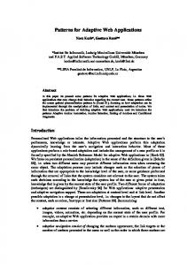
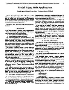
Following the Unified Process [9], the functional requirements of web-enabled applications are captured by use cases where interesting scenarios are detailed by means of sequence diagrams. As a running example throughout the paper we use the model of an online shop. As shown by the use case diagram in Fig. 1, a client of the online shop can query products, order a product, or pay for an order. If the client wants to pay, for example by credit card, his credit card data has to be verified before he gets an acknowledgement. Therefore, the online shop uses the service of a credit card company to verify credit card data. Sequence diagrams are used to model scenarios like this in a more formal way as sequences of messages exchanged, in this case, between the client, the online shop, and the credit card company. Variants can be expressed by different sequence diagrams associated with the same use case. Figure 2 shows two sequence diagrams detailing the use case pay order. The initial segments of both scenarios are identical: The client who triggers the use case is asked by the online shop to enter his preferred method of payment, e.g., by automatic debit from the client’s bank account or by credit card. In our sample scenarios the client chooses to pay by credit card, which requires the transmission of the credit card data, e.g., the name of the credit card company, the credit card number, etc. The online shop sends the data to a credit card company for validation. The client gets a positive or negative feedback, depending on whether the credit card check has been successful or not. That means, we have one success and one failure scenario.
Online-Shop �
�
�
�
�
�
�
�
�
�
�
�
�
�
�
�
�
�
�
�
�
�
�
�
�
�
�
�
�
�
� �
�
�
�
�
�
�
Fig. 1. Use case diagram of the shop example
Model-Based Development of Web Applications
Online-Shop
CC-Company
Client
Online-Shop
173
CC-Company
Client payOrder()
payOrder
paymentMethod? selectPaymentMethod(byCCard)
paymentMethod? selectPaymentMethod(byCCard)
creditCardData? enterCreditCardData(CCData)
creditCardData? enerCreditCardData(CCData) validateCCData(CCData)
validateCCData(CCData)
validationResult=ok feedback(success) Pay by credit card - success
validationResult=notOk feedback(fault) Pay by credit card - failure
Fig. 2. Two scenarios describing the use case pay order
3
Platform-Independent Design
The requirements specification presented in Sect. 2 focuses on specific scenarios of the externally visible behavior of the application. In this section, we will complement this view, first moving from specific examples to general specifications and then from external requirements to the internal realization. The first step, called architectural design, describes the involved components and their possible interactions. This model is refined in the detailed design adding internal data state transformations. 3.1
Architectural Design
The structural view of the architectural design describes the components and interfaces of the online shop. We provide an interface for every use case, which is later implemented by a control class to execute the use case. Figure 3 shows the three components of our online shop. The online shop itself is a component with three interfaces for the three use cases in the diagram of Fig. 1. For each interface we can list the operations of the online shop that can be called by a client through that interface. In Fig. 3 we have only detailed the interfaces for the use case pay order and for the card validation use case of the credit card company. The data objects exchanged as parameters of operation calls between client and online shop as well as between online shop and credit card company are specified in a class diagram. We are qualifying the corresponding classes with stereotypes, one of the extensibility mechanisms of UML. The general notation for the use of stereotype is to enclose it in guillemots (��). We are using the stereotype boundary defined within the Unified Process [9] which is intended to designate GUI classes or forms that model the interaction between the system and its actors.
174
R. Heckel and M. Lohmann
Fig. 3. Components of the online shop example
Fig. 4. Boundary classes describing the exchanged data
Fig. 5. Protocol statechart for the component online shop
Whereas sequence diagrams are used to describe single scenarios from a global point of view, protocol statecharts are used to specify the sequences of requests individual components are willing to accept. Figure 5 shows the statechart for the interface payOrder corresponding to the use case pay order. The states are named according to the boundary classes whose instances are transferred to the client in response to the previous request. 3.2
Detailed Design
After having described components from an outside perspective, in this section their data structures and computations are modelled. Class diagrams are used to represent static aspects. Figure 6 shows the result of detailing the use case pay order. Beside the stereotype boundary introduced above, control and entity stereotypes are used (cf. again [9]): Each of these
Model-Based Development of Web Applications «control»
«boundary»
PayOrder
SelectPaymentData
+PayOrder() : SelectPaymentData +selectPaymentMethod(in p1 : SelectPaymentData) : BoundaryData +enterCreditCard(in p1 : bankAccountForm) : AcknowlegeData 0..1
0..1
0..*
«entity»
Order
-number -prize
0..1 «entity»
0..*
0..1 «entity»
Client
0..* 1
-name
175
1
CreditCard
-company -number
-paymentMethod «boundary»
CreditCardData -company -number
«boundary»
FeedbackData
-proofResult
0..*
Fig. 6. Platform-independent class diagram for online shop
stereotypes expresses a different role of a class in the implementation. Instances of control classes coordinate other objects, encapsulating the control related to a specific use case. Boundary classes are used to model interactions between the system and its actors. Entity classes model long-lived or persistent information. In addition to the static and dynamic diagrams of our models we now introduce a functional view integrating the other two by describing the effect of an operation on the data. This requires to move the focus both from sequences to single operations and from the externally visible behavior to its internal realization. To simplify this transition, we first take an operation-wise view on the externally visible behavior. To this aim we introduce for each operation abstract reaction rules, which are derived from the sequence diagrams. For example, Fig. 7 shows the abstract reaction rules for the success scenario of Fig. 2. The left-hand side of the rule contains the method call on the component as part of the precondition of the operation. The right-hand side shows the visible effects, i.e., a message sent to another component. Next, the internal data state transformation associated with this operation is described. Figure 8 shows the refinement of the lower right abstract reaction rule of Fig. 7. The left-hand side of the diagram represents the precondition of the rule, i.e., that the validation of the credit card has been successful. The right-hand side shows the desired effect of the execution: A new boundary object with an acknowledgement is created. One benefit of this form of specification integrating static and dynamic models is that it provides a detailed and precise enough specification to allow automatic code generation (cf. [3]) which is an essential for the goal of model-driven development. To stick with standard UML notation, reaction rules can be expressed as collaboration diagrams where pre- and post-conditions are jointly represented in one diagram. In order to distinguish objects that are created or deleted, the stan-
176
R. Heckel and M. Lohmann
Fig. 7. Abstract reaction rules
Fig. 8. Refinement of lower right abstract reaction rule of Fig. 7
dard constraints new and destroyed are used. As an example, Fig. 9 shows the corresponding representation of the reaction rule of Fig. 7. This correspondence between collaboration diagrams and graph transformation rules can be extended to more sophisticated cases where complex scenarios are modelled within one diagram [6]. In this case, rather than a single rule, a graph process is required, i.e., a partially ordered set of interrelated rules each modeling a single step of the interaction.
Model-Based Development of Web Applications
177
Fig. 9. Reaction rule of Fig. 8 expressed with collaboration diagram
4
Integrating Platform-Independent and Platform-Specific Models
In the next two subsections we show how to map the platform-independent models developed in the previous section on platforms like HTML or SOAP which realize the request-query/update-response pattern. Model information required for this mapping is captured in the platform-specific design. The aim is to deploy code generated from platform-independent models on a specific middleware while keeping platform-independent and platform-specific models separated. 4.1
Platform-Specific Design
In many web-enabled applications a middleware serves as a link between clients and back-end services. This middleware is normally responsible for the implementation of the chosen base technology. For example you can use a web server which implements the Java Servlet technology [18] to implement an HTML application or you can use a SOAP server to implement a SOAP-based [19] application. In both cases a client doesn’t send a request directly to the application. Instead a client addresses the middleware and this middleware requests the application with pre-defined interfaces. Figure 10 shows an abstract overview how a web application realized with the Java Servlet technology works. A user normally fills in an HTML form on the client and by clicking the Submit button the form data is send to the server (1). The server locates the requested application, more exactly he locates an
178
R. Heckel and M. Lohmann
2: procedure call
1: request