Certification of Development Tool-chains *. B. Polgár, I. Ráth, Z. Szatmári, Ã. Horváth, and I. Majzik. Department of Measurement and Information Systems,.
Model-based Integration, Execution and Certification of Development Tool-chains ? ´ Horv´ath, and I. Majzik B. Polg´ ar, I. R´ ath, Z. Szatm´ari, A. Department of Measurement and Information Systems, Budapest University of Technology and Economics Magyar Tud´ osok krt. 2, Budapest, Hungary, H-1117 {polgar,rath,szatmari,majzik}@mit.bme.hu
Abstract. Software development processes are typically supported by a set of different tools that assist the designer in various phases of development like modeling, verification, source code generation, testing. Tool-chains can be formed by the integration of tools that are related to the subsequent steps of the process. In this paper, we present a tool integration framework which applies metamodel-driven and process-centric design patterns. Motivated by our research activities in various projects, our framework is based on standard process models, which allows the re-use of tool integration patterns as well as automated checking of the conformance of tool-chains to development standards. We make use of the state-of-the-art Rational Jazz platform as a technological basis.
1
Introduction
Motivation. During system development – especially in the development of safety-critical systems, e.g., in the field of automotive, avionics or railway – several tools are used for the different aspects, i.e., for modeling, transformation, verification, testing, analysis and code generation. We faced the challenge in several of our projects to integrate these tools. For instance, the DIANA project [1] aims at the implementation of an enhanced avionics platform, named AIDA (Architecture for Independent Distributed Avionics, [2]). Along with this objective, a primary research goal is to develop a tool chain to be used for AIDA, which incorporates standard modeling tools for SysML, OCL, JML and various other domain-specific languages. Within the framework of this project, our efforts are concentrated on designing and implementing the integrated end-to-end design tools with transparent transformations which are used to automatically map the design and specification models to analysis and validation domains for a thorough verification and validation process. The goal of the MOGENTES project [3] is to significantly enhance testing and verification of dependable embedded systems by means of automated generation of efficient test cases from engineering models. In the project the ?
This work was partially supported by the European Union as part of the FP7-STREP MOGENTES (216679).
newly developed test generation technologies should be integrated with existing modeling tools and with the test environment of the industrial partners. The integration should be realized in a seamless way, i.e., domain experts with limited knowledge and experience in usage of formal methods (that will be used for test generation) should also be able to use them with minimal learning effort. Related Work. Tool integration has been a hot research topic over the past years. There have been a number of early attempts (such as [4]) at integrating development tools within the context of a well-defined process. With a tendency to use non-standard technologies for various critical components, they were rather suited for a particular type of application rather than being generally usable. However, the experience from these approaches has been collected and synthesized into design patterns [5] which are common to most tool integration approaches of today. An important class is metamodel-driven tool integration [6], which is based on the idea of a model bus, a data repository which captures semantic information on the data that is exchanged between the tools and provides uniform persistence support. Recent initiatives ([7, 8]) target advanced features such as model difference computation and model merging, but their scalability to industrial model sizes (a few million model elements) is yet to be evaluated. The workflow-based approach [9] has been (partially) implemented in a number of tools. The SENSORIA Development Environment [10] offers Eclipse-based integration interfaces and a simple orchestration language in which small tool integration processes can be described. jETI [11], a similar tool integration framework, is targeted at remote invocations for Eclipse-based tools using Web Services technology. With the increasing emphasis on organized collaborative work in software development, high-level team management tools such as Rational Jazz [12] are emerging, driven by precise process models exported from modeling environments like the Rational Method Composer or its open source variant, the Eclipse Process Framework Composer [13]. Goals. In our solution we did not want to develop a completely new framework rather to achieve our goals by reusing and combining existing technologies and extending them if necessary. Thus, our approach is targeted as a complementary contribution to high-level collaboration integration environments. We apply both the metamodel-driven and the process-driven tool integration patterns with a special focus on certifiability, and integrate low-level tool integration workflows with high-level process descriptions. With our solution we address the following properties: – Definition of a flexible framework. In the architecture key components are identified independently of the underlying technology. For the implementation of the components high level, modern technologies having strong industrial support are used if possible. Between the components well-defined interfaces are defined in order to be able to change the implementation technology.
– Model-based construction and execution of tool-chains. The integration of tools required for a given activity is specified using a process model that includes the tasks, the supporting tools, and the input/output artefacts. The process models will directly form the basis of executing the corresponding tool-chains, this way the domain expert is able to focus on the semantics of the tool-chain without dealing with specific lower level notations and configuration options of the process execution engine. The process model is mapped automatically to the input language of a process execution engine that invokes the tools specified in the process model and ensures the proper handling of the related artefacts. – Data integration. The artefacts processed and generated by a tool-chain are stored in a persistent data repository, where meta-information can be assigned that supports version control, traceability and other related tasks. – Certification of Processes. To reduce the risks of software design failures, the software development processes are more and more subject to regulations fixed in (domain-specific) standards that define criteria for the selection of techniques and measures. An automatic assessment process for development tool-chains is proposed based on logic-based description of requirements stated in the standards. The standards for safety-critical systems define safety integrity levels (SIL) for development processes and describe methods that can be applied to the tool-chains. An ontology based representation of these requirements and the development process is constructed and the certification using a reasoner tool is performed. The paper is organized as follows: the architecture with key components are described in the next section. Section 3 discusses in more details the approaches for process modeling and process certification, while Sec. 4 demonstrates the concepts in a case study that contains details about a prototype implementation. Finally we conclude our recent work and sketch the future work.
2
Architecture
Based on our research and development experience and on the related works in the field we have identified the key components that are needed to fulfil the goals described in the introduction. The architecture composed of these components can be seen in Fig. 1. Process Modeling. The basis of the framework is the Process Model created and edited by the Process Editor: it contains the information about who does what, on which artefact, with which tool. This model describes (i) tasks, i.e., the modeling, analysis, verification and other steps of the development process, (ii) tools that are used to create, modify, test, generate, verify, transform, etc. some of the handled artefacts, (iii) artefacts that can be models, files or anything that contain information handled during the process, and (iv) roles of acting persons. Process modeling can be performed on different levels with different Process Editors; this is discussed in more details in Sec. 3.1.
Fig. 1. Framework architecture
Tool Management. A Tool represents an executable program that performs one or more tasks during the development. Tools are independent of the framework and can be implemented in different languages (e.g., in Java or in C) and according to different technologies (e.g., as standalone program or as web service). The only requirement is to be programmatically invocable, i.e., have the business functionality exposed to a well-defined interface which is externally accessible (ranging from command line interfaces to library functions). Connectors are the components that provide uniform interface of the tools for the framework. These invoke the tools, where the invocation can be anything: function invocation, remote procedure call, command line execution, web service invocation, etc. These may provide multiple interfaces — and thus multiple functionalities — of single tools. Upon invocation the connector retrieves the input artefacts needed by the tool from the Data Repository, and uploads the output artefacts provided by the tool to there (both through the Artefact Manager). It may also derive traceability information from the input and output artefacts. The Tool Manager manages the tools through the connectors. This way the heterogeneity of the tools are handled by the connectors and the Tool Manager needs to handle only components (the connectors) that have uniform ’appearance’. The instances of these uniform components are stored in the Tool Repository. The Tool Manager shall provide a mechanism for the registration of connectors and it is responsible also for the initialization and finalization of them. Data Management. Models and other data files (i.e., artefacts) that are handled during the development process (especially in the tool-chains) are described in the Process Model. These are input and output data of the tools and the purpose of data management is to handle these in a uniform way and storing these in a central repository (or in distributed repositories) extended with version, traceability and other information (e.g., type, related dates, creator). The Artefact Manager is the component that provides data handling and traceability related services to the other components of the framework (to the
Connectors and to the Process Execution User Interface). The handled information is stored in the Data Repository component. Process Execution. The purpose of the process execution is to manage and trace the execution of workflows (tool-chains) defined in the platform-specific process model that comprises tools contained by the Tool Repository and references data contained in the Data Repository. The execution can be initiated and supervised on the Process Execution User Interface and it is performed by the Process Execution Engine. The Process Execution User Interface provides a control panel for the users where (i) execution of tasks defined in the platform-specific process model can be initiated, (ii) state of execution can be traced, and (iii) versions of artefact instances and their related metadata can be managed and traced. The Process Execution Engine is responsible for the execution of the steps defined in the Process Model. When execution is initiated tool instances (connectors) associated to steps in the Process Model are retrieved from the Tool Repository through the Tool Manager and their services are invoked. When invoking services, references to the input data are provided to the connectors, which then retrieve these from the Data Repository and invoke the external tools with them. After the execution has finished the engine feeds back the status information to the supervisory interface (Process Execution User Interface).
3 3.1
Modeling and Certification of Processes Process Modeling
In our work those steps of the development process are of special interest that refer to the execution of tools and even those parts where these steps form a sequence — hence the related tools form a tool-chain — and this can be executed (semi-)automatically. Thus the aim of the process modeling can be conceived as to have a description of the tool-chains that have to be executed at given points in the development process. Based on this model we have the following goals: (i) derive deployment models as automatically as possible (ii) enable the certification of processes by proving its correspondence to the requirements of development standards. The Process Model is constructed according to the MDA concepts: it has a platform-independent version, which is a logical model where tools appear only on abstract level (e.g. as an abstract tool or defined in a task by referring the execution of a given tool) and it has a platform-specific version, which is an instrumented model where all execution related information about the tools are present. The creation of the platform-independent process model can be supported by design patterns in the editor, which patterns shall be constructed on the basis of standards, related domain requirements or best practices.
The platform-specific model is created from the platform-independent one: this step consists of the binding of concrete tools contained by the Tool Repository to the abstract tools. Two types of deployment models are generated from the platform-specific model: (i) the Workflow Model contains the description of the tool-chain to be executed in the format that can be executed by the Process Execution Engine, (ii) the Storage Model is the description of the data structure in a format that is needed to configure the Data Repository. These components and their relations are depicted in Fig. 2 extended with some implementation related information that is discussed in Sec. 4.
Fig. 2. Models and their relations used in process modeling and execution
3.2
Process Certification
The certification process necessitates the following tasks: – Formalization of the requirements (criteria) in standards that concern the selection of methods and tools. – Definition (or adaptation) of modeling techniques to describe the relation of methods, the capabilities of tools, and the construction of (domain-specific) development processes. – Elaboration of techniques that check the compliance of concrete development processes (constructed by process designers) to the requirements. In the standards the methods are refined hierarchically, i.e., several high level methods are decomposed into alternative combinations of lower level ones, and sufficient conditions for every SIL are formulated using various combinations of the applied methods. A formal representation of the hierarchical structure of methods is provided by defining an ontology [14]. Here concepts refer to the development methods and their relations include the refinement. The next step of the formalization process is the categorization of the tools in the tool repository. Each available tool in the tool repository is classified on the basis of the concepts defined in the ontology, according to the supported methods. Finally, the (domain-specific) development process model is mapped automatically to an ontological representation, in order to support the logical reasoning. According to the approach described above, all of the tasks, the tools and thus the development processes are characterized using the concepts represented
in the ontology. Using these concepts, the necessary and sufficient conditions for the selection of methods and the dependency on the safety integrity level are represented using ontology queries [15]. This way the standard conformance of the selection of methods and their supporting tools in the development process can be checked using an ontology reasoner. In our research we used the Protege [16] ontology modeling tool and the Racer Semantic Web Reasoning System [17].
Fig. 3. The certification process
In Fig. 3 the assessment process is depicted. Based on the domain specific standard the Methods Ontology and the Requirements can be constructed. The development process can be modeled using the process model of OMG (SPEM – Software Process Engineering Metamodel) and this Process Model should be transformed into an ontology model. Finally, the standard conformance of the development process can be checked using the reasoner tool.
4
Case Study
Prototype Implementation. To support the goals outlined in Sec. 1, we have designed and implemented a prototype framework. Our prototype implementation is composed of the following software systems: 1. Platform-independent Process modeling is carried out with the Eclipse Process Framework Composer [18] (ver. 1.5) (which is essentially the same as Rational Method Composer 7.5) that is based on the SPEM metamodel. Platform-specific process models are designed with a domain-specific language and editor developed with the ViatraDSM tool [19]. 2. Model transformations between platform-independent and platform-specific process models, as well as storage and executable process models are implemented as VIATRA2 [20] transformation plugins. 3. Tool management is performed by the Rational Jazz Platform (ver. 0.6). Tool connectors are implemented as Jazz service plugins. For data management, we use the Jazz’s data repository [21]. Artefact management services are provided by Jazz Services working on EMF-based storage models, and the Apache Derby relational database management system is used as the underlying Data Repository.
4. Finally, we integrated the JBoss jBPM workflow engine as a Jazz service [22] (ver 3.2) to be used for process execution and monitoring. To allow the jBPM engine to invoke tools through connector interfaces, we implemented lightweight action adaptors which serve as plug-ins to the jBPM environment. Description of the example. The example is taken from the MOGENTES project [3], where the goal is the model-based generation of efficient test cases. Let’s consider a usual development process where the system is modeled in UML using state charts for defining the behavior of objects. During structural testing, the test goal is to have full state and transition coverage with a possibly minimal number of tests. For this reason, the state chart model is transformed to the language of the SAL model checker [23] and test sequences are generated with the SAL-ATG tool [24].
(a)
(b)
Fig. 4. Views of the Process Model in EPF Composer a) Activity Diagram b) Detailed Activity Diagram
Originally, this process is captured as an iterative procedure, where the test cases are executed until all test requirements are fulfilled (the results from testing are used as feedback for the modification of the models). For the sake of simplicity, we use a simplified version of this process where no iteration cycles are involved. Thus, the test generation workflow appears in the process model with two tasks: it is composed of a transformation task and a test generation task. Both are realized as the execution of a tool, thus it forms a small tool-chain which is executed by the test engineer. In the following, we demonstrate how the goals formulated in the introduction are fulfilled by the framework described above. 4.1
Process Modeling
Platform-independent process model. The first step is the construction of the tool-chain as a high level EPF process model. We may start with high level
design patterns but the goal is to create a detailed process model where all necessary tasks are concretized (with associated roles, tools and work items); see Fig. 4. Platform-specific process model. The platform-specific process model can be derived from the high level EPF model by an automated model transformation in VIATRA2. The model is augmented with platform-specific information (such as tool IDs, tool interface function invocation parameter mappings, and work item metadata) in a domain-specific editor, implemented in ViatraDSM (Fig. 5(a)).
(a) Platform-specific process model
(b) jPDL workflow model
(c) Storage model for the IBM Rational Jazz Platform Fig. 5. Platform-specific models
4.2
Process execution
Workflow deployment model. We use the platform-specific models to derive deployment models for process execution and data management. For process execution, we use an annotated JPDL model which can be directly interpreted by the JBoss jBPM engine (Fig. 5(b)). The JPDL description includes invocation information and parameter passing mapped to process variables, which are used by our process plug-ins at run-time to facilitate the execution of tools with proper data. Data deployment model. For data management, we use the Data Repository component of the Rational Jazz Platform. It uses an EMF-driven metadatabased object repository, where the “schema” is specified by a storage model (defined as an annotated EMF model, Fig. 5(c)). This model is automatically
created from the platform-specific models and contains information about the relationships between various artefact types (such as containment, cross references) and metadata attributes. The actual data items that are used in the workflow are stored as BLOB attributes in the storage model, with metamodel-based versioning management support (elements derived from the Auditable type are automatically versioned by Jazz). Execution. The data management system and all tool connectors are implemented as Jazz Services, which can be invoked through Java function calls (locally) and Java RPC (remotely)1 . Tools along with connectors are deployed on the tool integration server, which is accessible to clients (workstations). In the example scenario, the system consists of the following Jazz services: – tool services: the UML2SAL model transformation, and the SAL-ATG test generator are deployed as stand-alone services on the Jazz server; – the data access service is generated for the storage metamodel (supporting specific queries) and deployed on the Jazz server; – the integration workflow service makes use of the workflow execution infrastructure service (the JBoss jBPM executor in the prototype) and exposes a separate Jazz service for the invocation of the entire workflow. For instance, if a test engineer wishes to execute the test generation process, she may connect to the Jazz server from within her Eclipse workbench, create the UML statechart models, upload the models to the repository, invoke the integration workflow service (with proper parameter passing) and retrieve the resulting test cases from the repository. 4.3
Certification
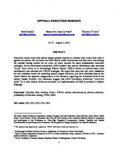
The assessment of the process can be executed on the basis of a required standard. In this example we refer to the EN50128 standard [25]. In Fig. 6 the hierarchy of the methods described in the Verification and Testing step of this standard is presented. For every method the recommendation level is indicated (mandatory (M), highly recommended (HR), recommended (R) and not recommended (NR)) and the combination of the required methods is expressed as a logical condition. Based on the hierarchy of methods an ontology is constructed as mentioned in Sec. 3.2. Both the tools and tasks described in the tool level and task level process model are categorized using the concepts of the ontology and tool-chain patterns are proposed in order to support high level methods in the development process. For example, Structure-Based Testing (which is a Dynamic Analysis and Testing method) can be supported by the following tool-chain: 1
While Jazz supports remote calls through RESTful web services, at this implementation stage we have not used that functionality.
Fig. 6. Methods hierarchy in the Verification and Testing step
1. Model transformation from UML2 statechart model to the input format of the SAL model checker. 2. Test generation for a given coverage criteria using the SAL-ATG [24] tool. 3. Mapping abstract test cases to executable test cases. 4. Execution of test cases and measuring coverage by Rational RealTime. The process model that includes this tool-chain can be validated using the ontology reasoner according to the hierarchy of methods presented in Fig. 6. It turns out that in order to satisfy the requirements for SIL3 and SIL4, other methods (and supporting tools) are also necessary.
5
Conclusions
The tool integration framework presented in this paper supports the goals targeted in the introduction: (i) the different tasks arising during tool integration — namely process modeling, process execution, tool management and data management — are supported by the framework, (ii) these tasks are separated on component level, (iii) for the implementation of these components widely supported technologies are used, e.g., Jazz, EPF Composer, Apache Derby, jBPM, domain specific modeling, (iv) construction of process models that conforms to development standards are supported by the application of process design patterns, (v) certification of development processes is supported by an automated approach that check the conformance of the processes to standards using ontologies. The feasibility of our approach was demonstrated by a prototype implementation and was illustrated on a case study.
References 1. The DIANA Project Consortium: DIANA (Distributed, equipment Independent environment for Advanced avioNic Application) EU FP6 Research Project http: //dianaproject.com. 2. Skysoft, Inc.: The AIDA System (DIANA Project White Paper). Technical report, The DIANA Project, EU FP6 (2008) http://diana.skysoft.pt. 3. The MOGENTES Project : MOGENTES (Model-based Generation of Tests for Dependable Embedded Systems) EU FP7 Research Project http://mogentes.eu.
4. Einar W. Karlsen: The UniForM WorkBench: A Higher Order Tool Integration Framework. Lecture Notes In Computer Science 1641/1999 (1999) 266–280 DOI 10.1007/3-540-48257-1 17. 5. G´ abor Karsai, Andr´ as Lang, Sandeep Neema: Design patterns for open tool integration. Software and Systems Modeling 4(2) (2004) 157–170 DOI 10.1007/s10270004-0073-y. 6. Carsten Amelunxen, Felix Klar, Alexander K¨ onigs, Tobias R¨ otschke, Andy Sch¨ urr: Metamodel-based Tool Integration with MOFLON. In: International Conference on Software Engineering, ACM (2008) 807–810 DOI 10.1145/1368088.1368206. 7. Rick Salay et al.: An Eclipse-based Tool Framework for Software Model Management. In: OOPSLA Workshop on Eclipse Technology eXchange, ACM (2007) 55–59 DOI 10.1145/1328279.1328291. 8. Elisabeth Kapsammer et al.: On Models and Ontologies - A Layered Approach for Model-based Tool Integration. In: in Proceedings of the Modellierung 2006 (MOD2006). (2006) 11–27 9. Flavio Corradini, Leonardo Mariani, Emanuela Merelli: An agent-based approach for tool integration. International Journal on Software Tools for Technology Transfer 6(3) (2004) 231–244 DOI 10.1007/s10009-004-0158-5. 10. Howard Foster, Philip Mayer: Leveraging Integrated Tools for Model-Based Analysis of Service Compositions. In: 3rd International Conference on Internet and Web Applications and Services. (2008) DOI 10.1109/ICIW.2008.103. 11. Tiziana Margaria, Ralf Nagel, Bernhard Steffen: jETI: A Tool for Remote Tool Integration. Lecture Notes in Computer Science 2440/2005 (2005) 557–562 DOI 10.1007/b107194. 12. IBM Rational: Jazz Community Site http://jazz.net/. 13. Peter Haumer: Increasing Development Knowledge with Eclipse Process Framework Composer. Eclipse Review (2006) 14. S. Bechhofer: OWL reference. W3C recommendation. (2004) 15. Karvounarakis, G., Alexaki, S., Christophides, V., Plexousakis, D., Scholl, M.: Rql: A declarative query language for rdf. In: Proceedings of the eleventh international conference on World Wide Web. (2002) 592–603 16. Protege: Protege ontology editor http://protege.stanford.edu/. 17. Racer Systems Gmbh: Racer Semantic Web Reasoning System and Information Repository http://www.racer-systems.com/. 18. The EPF Project: website http://www.eclipse.org/epf/. 19. R´ ath, I., V´ ag´ o, D., Varr´ o, D.: Design-time Simulation of Domain-specific Models By Incremental Pattern Matching. In: 2008 IEEE Symposium on Visual Languages and Human-Centric Computing (VL/HCC). (2008) 20. Varr´ o, D., Balogh, A.: The model transformation language of the VIATRA2 framework. Science of Computer Programming 68(3) (October 2007) 214–234 21. R. Frost: Jazz and the Eclipse Way of Collaboration. IEEE Software 24(6) (2007) 114–117 Digital Object Identifier: 10.1109/MS.2007.170. 22. John Koenig: JBoss jBPM White Paper. Technical report, The JBoss Group / Riseforth.com (2004) http://jbossgroup.com/pdf/jbpm\_whitepaper.pdf. 23. SAL: Symbolic Analysis Laboratory (web site) http://sal.csl.sri.com. 24. Gr´egoire Hamon, Leonardo de Moura, John Rushby: Automated Test Generation with SAL. Technical report, SRI International, Menlo Park CA 94025 USA (2005) http://www.csl.sri.com/users/rushby/papers/salatg.pdf. 25. CENELEC: EN 50128: Railway applications - Communication, signalling and processing systems - Software for railway control and protection systems. http: //www.cenelec.eu.