Distribution patterns, Web services, compositions, decen- tralisation, MDA .... Deployed. Executable. System. Interaction Logic/. Interfaces/. Deployment. Descriptors .... Table 1: Detailed description of DPLProfile stereotypes attributes. Attribute.
Model Driven Distribution Pattern Design for Dynamic Web Service Compositions Ronan Barrett, Claus Pahl
Lucian M. Patcas, John Murphy
School of Computing Dublin City University Dublin 9, Ireland
School of Computer Science and Informatics University College Dublin Belfield, Dublin 4, Ireland
{rbarrett|cpahl}@computing.dcu.ie
{lucian.patcas|j.murphy}@ucd.ie
ABSTRACT Web service compositions are often used to realise servicebased enterprise applications. These enterprise systems are built from many existing discrete applications, often legacy applications exposed using Web service interfaces. Acceptance of these systems is often constrained by non-functional aspects, such as Quality of Service (QoS). A number of factors affect the QoS of an enterprise system, including availability, scalability and performance. There are a number of architectural configurations or distribution patterns, which express how a composed system is to be deployed. These distribution patterns have a direct impact upon the QoS of the composition. However, the amount of code required to realise these distribution patterns is considerable. Additionally, there is an increased deployment time associated with setting up different distribution patterns. We therefore propose a novel approach which combines a Model Driven Architecture using UML 2.0 for modeling and subsequently generating Web service compositions, with a method for achieving dynamic decentralised interaction amongst services with reduced deployment overheads. These approaches combined provide for the generation of dynamic Web service compositions driven by a distribution pattern model.
Categories and Subject Descriptors D.2.11 [Software Engineering]: Software Architectures— languages, patterns
General Terms Design, Management, Performance, Reliability
Keywords Distribution patterns, Web services, compositions, decentralisation, MDA
1.
INTRODUCTION
Service-based enterprise applications are often realised by composing a number of Web services. The development of such composite Web services is often ad-hoc, without regard for non-functional requirements, and requires considCopyright is held by the author/owner(s). ICWE’06, July 11-14, 2006, Palo Alto, California, USA. ACM 1-59593-352-2/06/0007.
erable low level coding effort for realisation [1]. We address these issues with a modeling approach, a non-intrusive decentralised interaction mechanism, and a solution for dynamic deployment of the composition, to address these issues. Our novel approach combines a Model Driven Architecture using UML 2.0, for modeling and subsequently generating Web service compositions, with a method for achieving decentralised communication amongst services. We also provide a Web service based facility for enabling the dynamic deployment of compositions. Our modeling approach suggests that Web service compositions have three modeling aspects. Two aspects, service modeling and workflow modeling, are considered by [18]. Service modeling expresses interfaces and operations while workflow modeling expresses the control and data flow from one service to another. We consider an additional aspect, distribution pattern modeling [21], which expresses how the composed system is to be deployed. Distribution patterns are an abstraction mechanism useful for achieving non-functional requirements or QoS [2]. Patterns express proven techniques, which make it easier to reuse successful designs and architectures [9]. Having the ability to model, and thus alter the distribution pattern, allows an enterprise to utilise distribution patterns which meet their QoS requirements. Two well known patterns are centralised and peer-to-peer, both of which offer different QoS characteristics. For example centralised patterns express high maintainability, but exhibit poor performance and scalability when compared to peer-to-peer patterns, due to a central message bottleneck [4]. We base our development approach on the OMG’s Model Driven Architecture (MDA) [8]. MDA considers models as formal specifications of the structure or function of a system where the modeling language is in fact the programming language. Having rich, well specified, high level models allows for the auto-generation of a fully executable system based entirely on the model. Our models will be generated based on existing Web service interfaces, requiring only limited intervention from a software architect, who defines the distribution pattern, to complete the model. Our approach provides a high level model which intuitively expresses, and subsequently generates, the system’s distribution pattern using a UML 2.0 based Activity diagram [7]. Some associated benefits of our modeling approach are isolation from the instability of unstandardised web composition technologies, as well as fast and flexible development of compositions. Motivated by these concerns,
we have devised an approach, a technique and an implementation, for the model driven design of distribution patterns. There is however additional deployment time overheads associated with enabling different distribution patterns. This effort is increased in proportion to the number of Web services in a composition or by a requirement for composition participants to be flexible [3]. Distribution patterns such as peer-to-peer have considerable QoS advantages, discussed in the following section, but have a large deployment overhead when compared to centralised approaches. We propose a mechanism which allows documents, necessary to describe decentralised interactions, to be passed for deployment and subsequent enactment to each participant in a composition. This approach enhances the service container of each participant to enable decentralised composition, while preserving the existing functionality of these services. The paper is structured as follows: section two discusses our modeling approach, some distribution patterns and decentralised composition issues; section three investigates our modeling and transformation technique, as well as a motivating case study; section four introduces our tool implementation; section five evaluates our approach; section six presents some related work; finally, section seven considers future work and concludes the paper.
2.
BACKGROUND
In this section, we provide some background to existing modeling approaches, present some distribution patterns and introduce some issues related to decentralised composition. There is a subtle difference between two of the modeling aspects within a Web service composition, namely workflows and distribution patterns [21]. Both aspects refer to the high level cooperation of components, termed a collaboration, to achieve some compound novel task [17]. Here, we consider workflows as compositional orchestrations, whereby the internal and external messages to and from services are modeled, as well as the business logic, from the perspective of only one of the participants in the composition. In contrast, distribution patterns are considered compositional choreographies, where only the external messages between services are modeled. Distribution patterns, as a compositional choreography, consider only the message flow between services. As such, a choreography can express how a system would be deployed. The compositional orchestration of these services are not modeled here, as there are many existing approaches [6, 10]. In fact the two approaches could be combined to provide a more complete model of the composition from both the workflow and distribution pattern perspectives. Distribution patterns in MDA terms are a form of platformindependent model (PIM), because the patterns are not tied to any specific workflow specification language. We consider there to be four basic distribution patterns, which are listed below and elaborated in [5]. • Centralised • Decentralised or Peer-to-Peer • Ring • Hierarchical
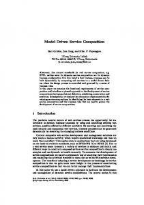
In order to exploit the potential of pattern-driven choreography definition, the consideration of a variety of patterns is beneficial, see Figure 1. Each pattern presents different QoS characteristics, such as varying levels of autonomy, performance, scalability and availability.
Centralised Pattern
Ring Pattern
Peer-to-Peer Pattern
Hierarchical Pattern
Figure 1: Examples of distribution patterns In a centralised pattern, a composition is managed in a single location by the enterprise initiating the composition. This pattern is the most widespread and is appropriate for compositions that only span a single enterprise. The advantages are ease of implementation and low deployment overhead, as only one controller is required to manage the composition. However, this pattern suffers from a communication bottleneck at the central controller. This represents a scalability and availability issue for larger enterprises [3]. The peer-to-peer pattern [21] addresses many of the shortcomings of the centralised pattern by distributing the management of the composition amongst its participants, resulting in improved scalability, availability and performance [3][14]. This pattern allows a composed system to span multiple enterprises while providing each enterprise with autonomy [20]. It is most important for security that each business acts upon its private data but only reveals what is necessary to be a compositional partner. In a peer-to-peer pattern, the initiating peer is only privy to the initial input data and final output data of a composition. It is not aware of any of the intermediate participant values, unlike a centralised pattern. The disadvantages of a peer-to-peer pattern are increased development complexity and additional deployment overheads. The ring pattern, is an enhancement of the centralised pattern. It features a cluster of computational resources providing load balancing and high availability. There is no longer a single point of failure or bottleneck as the load is spread across the entire ring, however all the participants are normally at the same physical site. Each of the participants in this pattern perform an identical function. The hierarchical pattern facilitates organisations whose management structure consists of a number of levels, by providing a number of controller hubs. This partitioning of the system allows for the delegation of work to departments, providing for security of data as well as scalability, as more controllers manage the compositions as the system scales up. The hierarchical pattern is easily extended by adding additional controlling hubs. The disadvantage of this pattern is
Step # 1
Step # 2
WSDL
Step # 3
Step # 4
Step # 5
Step # 6
UML 2.0 Model
DPL
Valid DPL
Interaction Logic/ Interfaces/ Deployment Descriptors
Actor
UML 2.0 Model
Distribution Pattern
Distribution Pattern
Distribution Pattern
Executable System
Deployment
Generator
Definition
Generator
Validator
Generator
Engine
UML 2.0 Model
UML 2.0 Model
DPL
Valid DPL or DPL errors
Interaction Logic/ Interfaces/ Deployment Descriptors
Deployed Executable System
Figure 2: Overview of modeling approach that there is a single point of failure at the root controller. If this controller fails the entire composition will fail. There are also complex variations of these distribution patterns, where a mix of two or more patterns are combined. Complex patterns are useful in that the combination of patterns often results in the elimination of a weakness found in a basic pattern. An example of a complex pattern is a “ring + centralised pattern”, which provides clustering for a highly loaded central controller. We also consider two other distribution pattern variants, dedicated hub and dedicated peer, which may be applied to the first two distribution patterns and their complex derivatives. For example, the addition of a dedicated hub to a centralised distribution pattern allows a composition to be initiated by a participant external to a composition. A similar scenario is where an additional peer is added to a decentralised pattern to initiate a composition. Web services, as passive participants within a composition often require mediation. This facet makes decentralised composition, necessary for some distribution patterns such as peer-to-peer, hard to achieve. However, the mediation or interaction logic, can be modeled centrally, and subsequently deployed to participants, provided that the runtime infrastructure of the participants supports enactment of the interaction logic[16]. Such characteristics, as well as the additional deployment overheads of decentralisation, should be addressed when attempting to enable decentralised compositions.
3.
MODELING AND TRANSFORMATION TECHNIQUE
In this section, we introduce the techniques we have developed for our distribution pattern modeling and transformational approach. There are four specific techniques listed below and elaborated in the six specific steps that follow. Each step is illustrated in Figure 2. • UML activity diagram/Profile extension (step 1,2) • DPL/DPL validator (step 3,4) • Generators (step 1,3,5) • Deployment Engine (step 6)
Our technique is motivated by a case study. The case study is an enterprise banking system with three interacting business processes. We choose an enterprise banking system as banks have specific QoS requirements, such as stringent controls over data management, as well as specific scalability and performance requirements, all of which are important factors when choosing a distribution pattern. Banks are also susceptible to changes in organisational structure, which necessitates a flexible distribution pattern. The scenario involves a bank customer requesting a credit card facility. The customer applies to the bank for a credit card, the bank checks the customer’s credit rating with a risk assessment agency before passing the credit rating on to a credit card agency for processing. The customer’s credit card application is subsequently approved or declined.
3.1 Step 1 - From Interface To Model The initial step takes a number of Web service interfaces as input. These interfaces represent the services which are to be composed. As Web services’ WSDL interfaces are constrained by XML Schemas, their structure is well defined. This allows us to transform the interfaces, using the UML 2.0 model generator, into a UML 2.0 activity diagram, an approach also considered by [6]. The UML model generated contains many of the new features of UML 2.0, such as Pins, CallBehaviorActions and ControlFlows [13]. A UML activity diagram is chosen to model the distribution pattern as it provides a number of constructs which assist in clearly illustrating the distribution pattern, while providing sufficient information to drive the generation of the executable system. Activity diagrams show the sequential flow of actions, which are the basic unit of behaviour, within a system and are typically used to illustrate workflows. UML ActivityPartitions, also known as swim-lanes are used to group a number of actions within an activity diagram. In our model, these actions will represent WSDL operations. Any given interface has one or more ports that will have one or more operations, all of which will reside in a single swim-lane. To provide for a rich model, we use a particular type of UML action to model the operations of the WSDL interface. These actions, called CallBehaviorActions, model process invocations and have an additional modeling
DPLProfile
Activity
ActivityPartition
CallBehaviorAction
InputPin
OutputPin
DPLMetadata
DPLPartition
DPLParticipant
+collaboration_language: CollaborationLanguage +distribution_pattern: DistributionPattern +service_name: String +base_namespace: String +namespace_prefix: String +operation_name: String
+ns: String +interface_uri: String +engine_uri: String
+name: String +role: Role +returns: Boolean
CollaborationLanguage
DistributionPattern
+WS-BPEL +WS-CDL
+centralised +peer_to_peer +ring +hierarchical +mesh +hybrid
DPLMessage +message_name: String +is_correlation_variable: Boolean
Role +peer +hub +spoke
Figure 3: UML profile for modeling distribution patterns constructs called pins. There are two types of pins, InputPins and OutputPins, which map directly to the parts of the WSDL messages going into and out of a WSDL operation. For our UML activity diagram to effectively model distribution patterns, we require the model to be more descriptive than the standard UML constructs allow. We use a standard extension mechanism of UML, called a profile [8]. Profiles define stereotypes and subsequently tagged values that extend a number of UML constructs. Each time one of these derived constructs is used in our model we may assign values to its tagged values. An overview of our profile can be seen in Figure 3, while the individual tagged values are described in detail in Table 1. The profile extends the Activity, ActivityPartition, CallBehaviorAction, InputPin and OutputPin UML constructs. This extension allows distribution pattern metadata to be applied to the constructs via the tagged values. For example, the distribution pattern is chosen by selecting a pattern from the DistributionPattern enumeration and assigning it to the distribution pattern tagged value on the DPLMetadata construct. The banking case study provides three WSDL interfaces as input to the UML 2.0 model generator. These interfaces represent the bank (CoreBanking), the risk assessment agency (RiskManagement) and the credit card agency (CreditCard). All three are represented in the generated UML activity diagram, albeit without any connections between them. A swim-lane is provided for each interface. Each interface has one operation, represented as a CallBehaviorAction, which is placed in the appropriate swim-lane. The message parts associated with each operation are represented as InputPins and OutputPins. These pins are placed on the appropriate CallBehaviorAction. No model intervention from the software architect is required at this step.
3.2 Step 2 - Distribution Pattern Definition The UML model produced in step 1, requires additional modeling. First the architect selects a distribution pattern and then assigns appropriate values to the tagged values of the stereotypes. The software architect must then define the sequence of actions by connecting CallBehaviorActions to one another, using UML ControlFlow connectors, guided by the chosen distribution pattern. The architect
must also connect up the UML InputPins and OutputPins of the model, using UML ObjectFlows connectors, so data is passed through the composition. Returning to the case study, we must connect up the three Web services to realise a distribution pattern. Before we do this, however, the architect must select a distribution pattern appropriate to the bank’s QoS requirements by applying values to the tagged values of the stereotypes. Some appropriate values can be seen in Table 1. The peer-topeer distribution pattern is appropriate as the bank requires credit rating information from a third party and does not wish to reveal any of the intermediate participant values of the composition. Also, the bank anticipates a high number of credit card applications, so the load must be distributed to avoid availability issues. Other scenarios would demand the use of other distribution patterns. The pattern is applied by connecting the CoreBanking and RiskManagement CallBehaviorActions together and subsequently connecting the RiskManagement and CreditCard CallBehaviorActions constructs together, using ControlFlow connectors, as in Figure 4. A dedicated peer is not used as the entry point to the composition, although this option is available. The InputPins and OutputPins of the CallBehaviorActions are connected together using ObjectFlow connectors, to allow the message parts propagate through the distribution pattern. An extra OutputPin, accountName, must be added to the RiskManagement CallBehaviorAction, to provide data for an InputPin, accoutName, to the CreditCard CallBehaviorAction.
3.3 Step 3 - From Model to DPL Using the model generated in step 2 as input, the model is transformed to a Distribution Pattern Language (DPL) document instance, using the distribution pattern generator. This document, which is at the same level of abstraction as the UML model, is an internal representation of the distribution pattern which can be validated. The DPL specification, written in XML Schema, and the document instance, an XML file, have no reliance on UML and so provide for interoperability with other modeling techniques. With regard to our case study, the ControlFlow connectors previously defined between the CallBehaviorActions are
Figure 4: Generated model with connections defined by software architect, viewed in IBM RSA
Attribute
Table 1: Detailed description of DPLProfile stereotypes attributes Description Example Value
collaboration language
Choice of collaboration language
WS-BPEL
distribution pattern
Choice of distribution pattern
peer-to-peer
service name
Name used by clients to consume the composition
BankingPeerToPeer
base namespace
Namespace URI for the composition, avoids name clashes
http://foo.com/wsdl/
namespace prefix
Namespace alias for the composition, avoids name clashes
BankingPeerToPeer
operation name
Operation name used by clients to consume the service
applyForCC
ns
Namespace URI of the participant, avoids name clashes
http://RiskManagement
interface uri
URI specifying the location of the participant’s interface
http://localhost/RM?WSDL
engine uri
URI specifying the location of the enactment engine
http://localhost/services/
name
Name of the participant in the composition
RiskManagement
role
Choice of roles for the participant from the Role enumeration
peer
returns
Last participant in the composition or not
false
message name
Name of the message from which the pin gets or puts its data
getAccountNameResponse
is correlation variable
Unique identifier field for a composition
false
used to assign an order value to the participant’s operations, which themselves are derived from the CallBehaviorActions (getAccountName, getRiskAssessment and getCreditCard) in the UML model. The ObjectFlow connectors between the InputPins and OutputPins are used to define the mappings between participants. The first participant does not require any explicit ObjectFlow connectors as the initial values passed into the system are used as its input automatically.
3.4 Step 4 - Model Validation The DPL document instance, representing the distribution pattern modeled by the software architect, is verified at this step by the distribution pattern validator, to ensure the values entered in step 2 are valid. The verification process ensures the distribution pattern selected by the software architect is compatible with the model settings. If incorrect values have been entered, the architect must correct these values, before proceeding to the next step. For example, in our case study, as the peer-to-peer distribution pattern has been chosen, there must be at least two participants with
a peer role and there must not be any participants with a hub role. If any errors are detected they must be corrected by the software architect by returning to step 2. Validation of the distribution pattern instance is essential to avoid the generation of an invalid system.
3.5 Step 5 - DPL to Interaction Logic The executable system generator takes the validated DPL document instance and generates all the interaction logic required to realise the distribution pattern. The generator creates the interaction logic documents based on the collaboration language setting. Interaction logic documents describe the message flow between the participants in the distribution pattern as well as input and output variable mappings. The generator also creates interfaces which expose the new interaction logic processing capability as a wrapper to the existing Web service functionality of the participant. A deployment descriptor document, describing the participants of the composition is also created for each participant. These documents are generated by parsing the DPL document instance and the WSDL interfaces associated with each par-
ticipant. Once deployed, these documents will realise the Web service composition, driven by the distribution pattern applied by the software architect. In our case study example, three WS-BPEL workflow documents are created to represent the interaction logic between the three peers in the distribution pattern. Three WSDL interfaces and three deployment descriptor documents are also created, all that remains is for the system to be deployed.
interaction logic. An ILDP can have any number of composition runtime interfaces enabling the participant to take part in many distribution pattern based compositions. ILDP engines realise a distribution pattern by enacting interaction logic documents and by communicating to each other using the composition runtime interface, if necessitated by the distribution pattern guiding the composition. Step #2
Step # 1
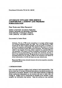
3.6 Step 6 - Interaction Logic to Deployed Executable System In the final step, the interaction logic, interface and deployment descriptor documents generated in the previous step are automatically passed to the participant services, by the deployment engine. We consider a novel enhancement to the container of each participant called Interaction Logic Document Processor (ILDP), see Figure 5(a). The ILDP enhancement must be installed on each participant, however this is a once off installation. ILDP enhanced participants are exposed as Web services, capable of receiving, processing and deploying these documents, see Figure 5(b). These enhanced participants can receive documents from the deployment engine. Subsequently the documents are processed by ILDP to ensure they are valid before storing them on the participant. Finally the stored documents are deployed by ILDP on the participant and exposed for composition by a composition runtime interface. An enactment engine, independent of ILDP, is responsible for enacting the interaction logic and subsequently invoking the participant services, facilitating decentralised interaction amongst the participant services. This approach negates any requirement of manually deploying documents to participant services. Moreover, as the mechanism enhances the container capability, it is non-intrusive to the existing Web service implementation or to the existing interfaces of the participant services. Deployment Engine Participant Services
Step # 3
ILDP Interface
ILDP Interface
Existing Interface
Existing Interface
Composition Runtime Interface
Figure 6: Participant interface evolution With regards to our case study, all three participant services, CoreBanking, RiskManagement and CreditCard will be contacted by the deployment engine. The engine will pass the relevant interaction logic, interface and deployment descriptor documents to the participant services. We assume each of the participant service containers has the ILDP enhancement installed, and is therefore capable of receiving, processing and deploying these documents at runtime, as well as subsequently enacting the interaction logic.
4. IMPLEMENTATION TOPMAN (TOPology MANager) is our solution to enabling distribution pattern modeling using UML 2.0 and subsequent dynamic Web service composition generation. The only technologies required by the tool are the Java runtime and both an XML and XSLT parser. The tool implementation is illustrated in Figure 7. UML 2.0 Model Generator
Send Documents Install ILDP on Participants
Expose ILDP as Web Service Interface
Model as XMI Profile as XMI
WSDL
RSA Manipulate UML2
XSLT/DOM
Receive Documents
Process Documents
XSLT/DOM
Deploy Documents SOAP Messages
(b)
Figure 5: ILDP Deployment The evolution of the participant’s interface can be seen in Figure 6. In step 1 the original Web service interface of the participant is visible. In step 2 the ILDP is installed and an additional interface is exposed by ILDP so it can receive interaction logic, interface and deployment descriptor documents. Finally in step 3, on receipt of documents, ILDP creates a composition runtime interface for participants in a particular composition to communicate to each other, using
Actor
Distribution Pattern Generator
Deployment Engine
(a)
Existing Interface
WS-BPEL(s) WSDL(s) PDD(s)
Distribution Pattern Validator
Executable System Generator DPL as XML XSLT/DOM
DPL XML Schema
Figure 7: Overview of TOPMAN tool The UML 2.0 model generator uses XSLT to transform the WSDL interfaces of the Web services participating in the composition, to a UML 2.0 activity diagram, which generates, using XML DOM, an XMI 2.0 [11] document. XMI is the XML serialisation format for UML models. The model generated includes a reference to our predefined UML profile for distribution patterns, which is also serialised to XMI 2.0. A number of tools may be used to describe the distribution pattern. IBM’s commercial tool Rational Software Architect (RSA) is compatible with XMI 2.0 and supports many of the UML 2.0 features. The tool has a GUI which
allows the software architect to define the distribution pattern. Upon completion, the model can be exported back to XMI for further processing by TOPMAN. An alternative to IBM’s commercial tool is UML2, an open source tool supporting UML 2.0, which allows the model to be viewed and manipulated in an editor. The distribution pattern generator uses XSLT to transform the UML 2.0 model to a DPL instance document. The DPL document instance is then verified by an XML validating parser. Finally the DPL document instance is used to drive the executable system generator. The executable system generator creates three distinct types of documents. XSLT and XML DOM are used to generate the interaction logic (realised here using WS-BPEL). WSDL interfaces and ILDP engine specific deployment descriptor documents, required by an ILDP compatible engine to participate in a composition, are also generated. Each participant in the composition must have an ILDP engine installed to enact interaction logic. Finally, depending on the distribution pattern chosen, the generated interaction logic, interface and deployment descriptor documents are distributed to the participants in the composition by the deployment engine. The deployment engine creates SOAP messages containing these documents and sends them to the ILDP enhanced service container, via the ILDP interface of each participant. Here we use WS-BPEL to implement the interaction logic, WSDL to implement a wrapper which exposes the interaction logic processing capabilities, and the ActiveBPEL specific Process Deployment Descriptor (PDD) to describe the composition participants. The ActiveBPEL workflow engine is used as the enactment engine which processes the interaction logic.
5.
EVALUATION
We assess our approach using the criteria set out in [18], along with some of our own criteria. • Pattern expression - We have identified a number of reusable distribution patterns and have shown how patterns can be expressed using UML with our DPLProfile extension and in XML, using our novel DPL specification. Different distribution patterns have different QoS characteristics such as availability, scalability and performance, as set out in section 2. • Readability - Our modeling approach, which visualises the distribution pattern, should be intelligible to software architects. As the model is at the PIM level, clutter from implementation details is avoided. • Executable - Our UML model and associated profile is sufficiently rich to generate a DPL document instance and subsequently all the interaction logic, interface and deployment descriptor documents needed to create an executable system. • Independence of technologies - As both our UML model and DPL instance document are modeled at the PIM level, there is no reliance on any particular workflow language. Also the container enhancement, ILDP, is not bound to any interaction logic or workflow languages such as WS-BPEL. • Maintenance overhead - Our MDA approach, using UML provides for easy manipulation of the system’s
distribution pattern. Additionally, the container enhancement we propose allows for increased flexibility to changes. Changes made to the distribution pattern after deployment time, have significantly reduced redeployment overheads, when compared with the manual deployment of interaction logic, interface, and deployment descriptor documents. Our ILDP enhancement, applied to the participant services, provides for dynamic deployment and enactment of the interaction logic documents. However, each participant within the composition must support this enhancement technology.
6. RELATED WORK Two workflow management systems motivate and provide concrete implementations for two of the distribution patterns explored in this paper. However, neither system provides a standards-based modeling solution to drive the realisation of the chosen distribution pattern. The first system DECS [21], is a workflow management system, which supports both centralised and peer-to-peer distribution patterns, albeit without any code generation element. DECS defines elementary services as tasks whose execution is managed by a coordinator at the same location. The solution is based on OPENFlow [12] which has a GUI for workflow management and is CORBA based. The second system SELF-SERV [20], proposes a declarative language for composing services based on UML 1.x statecharts. SELFSERV provides an environment for visually creating a UML statechart which can subsequently drive the generation of a proprietary XML routing table document. Pre- and postconditions for successful service execution are generated based on the statechart inputs and outputs. A related paper [3] provides some interesting performance metrics to confirm the advantages of peer-to-peer execution over centralised execution. From the modeling perspective Grønmo et al. [18, 6], consider the modeling and building of compositions from existing Web services using MDA, an approach similar to ours. However, they consider only two modeling aspects, service (interface and operations) and workflow models (control and data flow concerns). The system’s distribution pattern is not modeled, resulting in a fixed centralised distribution pattern for all compositions. Their modeling effort begins with the transformation of WSDL documents to UML, followed by the creation of a workflow engine-independent UML 1.4 activity diagram (PIM), which drives the generation of an executable composition. Additional information required to aid the generation of the executable composition is applied to the model using UML profiles. A tool called UMT [19] is provided to support their technique. Enabling distribution patterns such as peer-to-peer requires considerable work. A strategy, utilised by us, is introduced in [4] and described in [15], where workflow agents (ILDPs in our approach) are placed as proxies, at each participant to manage the distributed composition. These workflow agents manage the distributed composition by communicating directly to each other. The authors also consider build time and runtime issues of decentralisation. However, the problem of deploying decentralised compositions is left open, resulting in considerable deploy time overheads. We propose a mechanism for facilitating the dynamic deployment of decentralised compositions.
7.
CONCLUSION AND FUTURE WORK
A software engineering approach to the composition of service-based software systems is necessary. We have introduced techniques based on architectural modeling and pattern-based development. Our contribution is a modeling and transformation approach, technique and implementation for expressing the distribution pattern of a Web service composition. Our novel modeling aspect, distribution patterns, expresses how a composed system is to be deployed, providing for improved maintainability, comprehensibility, and varying QoS characteristics depending on the pattern chosen. Four modeling and transformation techniques were introduced, along with a tool (TOPMAN) which assists in the generation of an executable system. We have also contributed a mechanism for the dynamic deployment of decentralised compositions. Our novel mechanism ILDP, preserves the autonomy of services, by enhancing the service container of each participant. This approach results in significantly reduced deployment overheads and provides a mechanism to realise distribution patterns. However, we foresee replacing WS-BPEL as our interaction logic language, as it is overly complex for our interaction logic requirements. Instead we envisage a more concise interaction logic language, possibly a subset of WS-BPEL, and a compatible interaction logic document processor. Extensions to our modelling approach are being considered, based on integrating our approach with existing service and workflow modelling efforts [18], which could enable us to model more complex Web service compositions. We also envisage using semantics, which could reduce the software architects workload. Currently the connections and mappings between Web services must be made manually using our modeling technique. However if semantics were present the architect would simply choose a distribution pattern, possibly from a pattern repository, and the connections and mappings would be made automatically.
8.
ACKNOWLEDGMENTS
[7] [8] [9]
[10]
[11] [12]
[13]
[14]
[15]
[16]
This research is supported by the Irish Research Council for Science, Engineering and Technology (IRCSET) and the Advanced Technology Research Programme (ATRP), from the Informatics Research Initiative of Enterprise Ireland.
[17]
9.
[18]
REFERENCES
[1] G. Alonso, F. Casati, H. Kuno, and V. Machiraju. Web Services: Concepts, Architecture and Applications. Springer Verlag, 2004. [2] M. Barbacci. Quality Attributes. Technical report, CMU/SEI-95-TR-021, 1995. [3] B. Benatallah, Q. Z. Sheng, and M. Dumas. The self-serv environment for web services composition. IEEE Internet Computing, 7:40–48, 2003. [4] G. B. Chafle, S. Chandra, V. Mann, and M. G. Nanda. Decentralized orchestration of composite web services. In Proc. of the 13th international World Wide Web conference, pages 134 – 143, New York, NY, USA, May 2004. [5] D. Choon-Hoong, S. Nutanong, and R. Buyya. Peer-to-Peer Computing: Evolution of a Disruptive Technology. Idea Group Publisher, 2005. [6] D. Skogan and R. Grønmo and I. Solheim. Web service composition in uml. In Proc. 8th International IEEE
[19]
[20]
[21]
Enterprise Distributed Object Computing Conference, pages 47–57, Monterey, California, September 2004. H. E. Eriksson, M. Penker, B. Lyons, and D. Fado. UML 2 Toolkit. Wiley, 2003. D. S. Frankel. Model Driven Architecture: Applying MDA to Enterprise Computing. Wiley, 2004. E. Gamma, R. Helm, R. Johnson, and J. Vlissides. Design Patterns:Elements of Reusable Object-Oriented Software. Addison-Wesley, 1995. T. Gardner. Uml modeling of automated business processes with a mapping to bpel4ws. In Proc. First European Workshop on Object Orientation and Web Service (EOOWS), Darmstadt, Germany, July 2003. T. J. Grose. Mastering XMI: Java Programming with XMI, XML, and UML. Wiley, 2002. J. Halliday, S. K. Shrivastava, and S. M. Wheater. Flexible workflow management in the openflow system. In Proc. 5th IEEE/OMG International Enterprise Distributed Object Computing Conference, pages 82–92, Seattle, Washington, September 2001. G. Kramler, E. Kapsammer, W. Retschitzegger, and G. Kappel. Towards using uml 2 for modelling web service collaboration protocols. In Proc. First Interoperability of Enterprise Software and Applications, Geneva, Switzerland, February 2005. D. Liu, K. H. Law, and G. Wiederhold. Analysis of integration models for service composition. In Proc. 3rd international workshop on Software and Performance, pages 158–165, New York, NY, USA, 2002. ACM Press. M. G. Nanda, S. Chandra, and V. Sarkar. Decentralizing execution of composite web services. In Proc. 19th annual ACM SIGPLAN Conference on Object-oriented programming, systems, languages, and applications, pages 170–187, New York, NY, USA, 2004. ACM Press. L. M. Patcas, J. Murphy, and G. M. Muntean. Middleware support for data-flow distribution in web services composition. In The PhDOOS Workshop and Doctoral Symposium, ECOOP, Glasgow, UK, July 2005. C. Peltz. Web services orchestration and choreography. IEEE Computer, 36, 2003. R. Grønmo and I. Solheim. Towards modeling web service composition in uml. In Proc. 2nd International Workshop on Web Services: Modeling, Architecture and Infrastructure (WSMAI-2004), pages 72–86, Porto, Portugal, April 2004. R. Grønmo and J. Oldevik. An empirical study of the uml model transformation tool (umt). In Proc. First Interoperability of Enterprise Software and Applications, Geneva, Switzerland, February 2005. Q. Z. Sheng, B. Benatallah, and M. Dumas. Self-serv: A platform for rapid composition of web services in a peer-to-peer environment. In Proc. 28th International Conference on Very Large Data Bases, pages 1051–1054, Hong Kong, China, August 2002. S. J. Woodman, D. J. Palmer, S. K. Shrivastava, and S. M. Wheater. A system for distributed enactment of composite web services. In Work in progress report, Int. Conf. on Service Oriented Computing, Trento, Italy, December 2003.