In between the glue parts to transform the signals between ... 2http://www.chiastek.com/products/cosimate.html columns ... code generation, like timing information, converting to and ..... our lab, namely a mockup of a production cell, consisting.
Model-Driven Robot-Software Design using integrated Models and Co-Simulation Jan F. Broenink and Yunyun Ni*
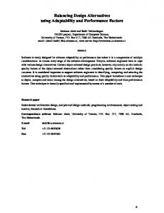
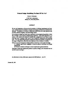
II. BACKGROUND A. Existing approach Fig. 1 shows a typical overview of an architecture used for robotic systems, containing the physical / mechanical plant (robot) at the right and the (embedded) control software at the left. In between the glue parts to transform the signals between the two domains are shown. In this paper, we concentrate on the embedded control software, although structuring of the other parts is also discussed.
* The authors are member of the Robotics and Mechatronics group (formerly Control Engineering), CTIT institute, faculty of Electrical Engineering, Mathematics and Computer Science, University of Twente, The Netherlands. E-mail: {j.f.broenink, y.ni} @utwente.nl
978-1-4673-2297-3/12/$31.00 ©2012 IEEE
339
Fig. 1.
Safety layer
Hard real-time
Loop control
Soft real-time
Sequence control
Non real-time
I/O hardware
Meas. & Act.
Embedded control software
Supervisory control & Interaction
I. I NTRODUCTION Robots, being a specific class of mechatronic systems, and being also a specific class of cyber-physical systems, are actually safety-critical cyber-physical systems. This calls for the total system, i.e. the cyber (computing) part and the physical part need to be described integrally, as both parts influence each other. Therefore, separate descriptions and treatment of the cyber and physical part do not suffice. Often, while developing embedded control software for robotic products, Model-Driven Development (MDD) [1] is used. However, mostly these existing MDD approaches are too much inclined to one discipline, either from a cyber / software engineering point of view, or from a physical / control point of view. To describe these two different parts (i.e. the cyber and the physical parts), two main Models of Computation (MoC) are used: a continuous time MoC (dynamic system (plant)) and a discrete event MoC (embedded control software). The modelling language used for the continuous-time MoC is the bond-graph notation, which is a domain-independent
notation for describing dynamic system behaviour [2], [3]. The modelling formalism used for the discrete event MoC is VDM (the Vienna Development Method), a formal specification language, with object-oriented and timing extensions (VDM++ and VDM-RT) to describe object-oriented and concurrent systems, and real-time systems [4], [5]. For comodeling and co-simulation of the combined models we use DESTECS1 [6] Besides, a sophisticated way of working is needed, which supports stepwise refinement from coarse-grained, global models to more detailed models, from which the embedded control software can be generated. To prevent design mistakes during this refinement, a tool chain that covers this refinement process completely is necessary to have. A manual step might compromise the correctness of the transformation done by hand, such that the quality of the resulting code cannot be guaranteed. This paper discusses a refinement method using integral models and co-simulation to support design of embedded control software in a Model-Driven way, such that the code generated at the end runs right the first time on the target embedded processor. Sec. II discusses the existing approach we use as starting point and some related work. Sec. III presents the method consisting of four steps. Sec. IV presents a case study, using a text-book like example. Sec. V draws conclusion.
User interface
Abstract— The work presented here is on a methodology for design of hard real-time embedded control software for robots, i.e. mechatronic products. The behavior of the total robot system (machine, control, software and I/O) is relevant, because the dynamics of the machine influences the robot software. Therefore, we use two appropriate Models of Computation, which represent continuous-time equations for the machine / robot part, and discrete event / discrete time equations for the control software part. To compute (simulate) such combined models, co-simulation of these models is used. The design work can be done as a stepwise refinement process, whereby each step is verified via co-simulation. This in general yields a shorter design time, and a better quality product. The tools pass model-specific information between each other via parametrized tokens in the generated, high-level code to get a better separation of design steps. This allows for better quality of the models and more reuse, thus enhancing the efficiency of model-driven design for the (industrial) end user. The method is illustrated with a case study using the tools, some of which are at the prototype level. Especially the structuring of the models and regularly doing simulations (of which some can be ’repeated’ as real experiments), is beneficial, shortening the development time and producing better models. Future work is to test the method on more complex cases, and to extend the method by detailing out the electronics and mechanics sub design flows.
D/A
Pl ant Power amplifier
Actuators Physical system
A/D
Filtering/ Scaling
Sensors
Software architecture for embedded systems
1 www.destecs.org
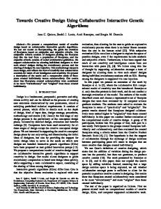
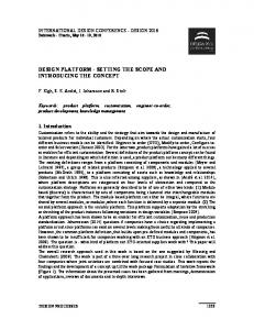
The embedded software part is structured in layers: • The Loop control block contains the control algorithms controlling the actuators. This needs to be hard realtime in order to make sure that the actuators are fed with new steering values each sampling period. • The Sequence control block is a kind of task level controller: it commands the loop controllers, by computing the set points of the control algorithms, and if applicable, enabling them and adapting parameters. The Sequence control block can be soft-real time. • The Supervisory control block is a strategy controller: calculations, often taking considerable amount of computing time (relative to the sampling period), that instruct the Sequence controller to determine its next task. Path planning or environment mapping are typically supervisory tasks. • The Safety layer block checks all signals going to the hardware. Safety issues are on all controller levels, shown by its U-form shape in the figure. For instance, obstacle avoidance is on the level of the loop controller, while graceful degradation is on higher levels. • The Measurement & Actuation block of the embedded control software denotes filtering and scaling to adapt the value ranges of the variables to the signal levels in the hardware. B. Related work Other co-simulation tools and approaches exist, like Cosimate2 , which provides a framework connecting different simulators. Cosimate has been tried out on the control of a mechatronic test set up [7]. It was concluded that the two models involved have to be connected in a rather cumbersome way. For Cosimate, the focus is on co-simulation tools coupling and not on the top-level architecture. Ptolemy II [8] has a heterogeneous simulation framework for modelling discrete event parts and continuous time parts (i.e. controllers and plant) within one model; however, it is not as domain specific as we are pursuing. The Design Tools and ViewCorrect projects developed the graphical tool gCSP [9]. This tool is capable of graphical modelling concurrent process-oriented software based on the CSP formalism [10]. Co-simulation of networked control systems has been tried out [11], but the tool never reached maturity. III. M ETHODS / A PPROACH In this section, a way of working (WoW) of embedded control software design using MDD techniques is described. It starts with a abstract model and ends with the code that can be executed on the embedded control computer, thus controlling the robot. A. Overview Fig. 2 gives an overview of the design flow; earlier versions are presented in [12], [13], [14]. In the figure, the
columns Electronics design and Mechanics design are greyed out, as the focus is on the embedded control software design, the middle three columns. However, some relations between the middle three and outer two columns are indicated. The figure shows four steps (numbered 1 to 4): 1) Global Architecture and Physical System Modelling, i.e. overall system structure and modelling of the plant. 2) Control Law Design, using the models obtained in the previous step. 3) Embedded Control System Implementation: the control software is designed via refinement of the control law(s). 4) Realization of the embedded software via an ongoing refinement process. Step 1 and 2 comprise the functional design, testing the embedded control software design against a dynamic model of the plant (called a virtual prototype). Step 3 and 4 deal with adding further implementation details, which are required for code generation, like timing information, converting to and from real signals, and running the code on the final target. B. Step 1: Global Architecture and Plant Model One can start with this step at different points: the overall software architecture (b in Fig. 2) or modelling of the plant (d in Fig. 2). It depends on the problem at hand (complex sequence / supervisory controllers versus complex plant dynamics / complex loop controllers) or the experience / background of the modeller, at which of the two entries one starts in this step. When starting at one side, the other side may be worked on in parallel, or incorporated in step 2. ECS software architecture is to construct the overall architecture of the embedded control software, and to build a structure in which control law implementations can be placed in Step 2. However, first versions of the supervisory and sequence controllers, consisting of reasoning and decisions, can be designed and tested here. When in this stage plant behaviour is needed, it suffices to mimic the plant by a stub that later will be exchanged by a connection to the plant model. Tooling and MoC must support a discrete event formalism to describe systems. In our case study, we use the Overture tool3 , implementing the VDM language. Plant dynamics modelling is obviously to create a competent model of the dynamic behaviour of the plant. So, only relevant and dominant aspects with respect to the purpose of the model need to be considered. Note, three main modelling purposes are the case here: • Design support, checking feasibility of the modelled solutions. • Derive control laws. • Test the system, using the model as a virtual prototype, so the control software is tested against the plant model instead of the real plant. These purposes demand different levels of detail of the model, and thus allow for a refinement throughout the whole
2 http://www.chiastek.com/products/cosimate.html
3 http://www.overture.org
340
Fig. 2.
Overview of the design flow
design trajectory. Actually, each of the Steps needs its own model. Feedback on correctness and competence of the model does not only come from verification via simulation, but also from other design Steps. In general, plant modelling starts with putting essential parts in the model. These initial models are verified via simulations. Then, the model is extended until it is satisfactorily competent, as indicated by the goal of the model. Tooling and MoC must support continuous-time and discrete-time way of describing systems. In our case, we use 20-sim4 and bond graphs [2], [15], [16]. The link between Plant dynamics and Mechanics design in Fig. 2 is to indicate that both structure of the dynamics model and values of parameters (like masses, springs) can be derived from the mechanics design (CAD) drawings. Methods and tools cover this, but we do not (yet) use this, as our focus is on the embedded control software. This approach allows for decoupling of the two disciplines involved, which appears to be advantageous in the beginning of design projects. C. Step 2: Controller design Obviously, one enters this step from the two distinct paths of step 1: working on the supervisory and sequence controller logic (b in Fig. 2) or developing and tuning the loop control laws, using the dynamic model of the plant (c in Fig. 2). The Software design flow focuses now explicitly on supervisory and sequence control logic and higher-level safety issues (like graceful degradation), so filling in details in the software architecture. Interfacing to the plant is still via stubs mimicking the plant’s input - output behaviour. The link between columns b and a in Fig. 2, is to indicate that for the detailed design of the software, one needs to know about facilities of the electronics. For instance, the 4 http://www.20sim.com
safety software depends on what facilities the (electronic) interface has: can the motors be switched off with just one signal? can the motors be short circuited to let the robot faster come to a halt? On the other hand, the software design work can pose requirements to the electronic design. When the global plant behaviour is not competent any more, one has to move to Step 3. The Loop control law design part focuses on designing and tuning the loop controllers. As the control laws will be realised on digital computers, the end result must be a discrete-time control law (also called a Time-Triggered control law. One can start directly with designing discretetime control laws, or start in the continuous time domain to derive a control law (i.e. using classical control theory), and convert the result to discrete time, whereby mostly retuning is necessary. The sample time Ts is generally chosen to be 10 times smaller than the dominant time constant of the plant to achieve a stable controlled system (i.e. no instability caused by the sampling). The control law is verified by simulating it, while controlling the detailed plant model achieved in step 1. The work here follows the existing approaches common in control theory and control law design. It might be necessary to simplify or linearise the plant model, as only a competent transfer function between actuation and sensing is needed. It may be necessary that more than one simplified model is needed to cover the whole working area of the controlled system. For each simplified model, a control law can then be designed. Mostly, more than one loop controller is needed, to cover all situations, for example, start-up, normal operation, exception handling. The co-operation between these different control laws need be taken care of in the sequence or supervisory controllers. Note that this is an example of co-design: easier work in the control law design part causes some extra work in the sequence controller design part.
341
D. Step 3: Embedded Control System Implementation In this Step, the two different flows of the early part of the design trajectory come together. In the 2 earlier steps, the functional design of the system has been made, and from Step 3 onwards, the focus is on adding further details to eventually generate the code for the target, and allowing the first-time right principle. This saves on-target debugging, which is harder than debugging while verifying the model using simulations and in a test environment. Traditionally, this implementation-preparation work is not done explicitly, and the results of Step 2 are often directly implemented, resulting in too much work in the final integration phase. This then leaves all modelling effort in the first two steps in vain. Therefore, Step 3 is a refinement process, in order to gradually enhance the functional description (software, architecture, control laws) towards a description from which the final code can be completely generated (so no handwritten glue code), such that it can be run directly on the target computer. Basically, we bring in extra descriptions to detail out the idealnesses assumed in Steps 1 and 2. Next to that, often descriptions dealing with fault handling are added here. The order to work out these details does not be followed in the way as we present it here. This gives the designer the freedom to tackle issues in an order, which fits best to the problem at hand, or to the designer’s experience. Further, iterative design is stimulated, as models and simulations are used. For the refinement towards implementation, the following issues are relevant: •
•
•
Integrate control laws. Combine the control law(s) with the sequence and supervisory controllers. Reaction to external commands, like from connected systems or from the operator, can be taken into account here. Design and test the transition from one control mode to another (bumpless transfer). Design and test functionality on machine-level, i.e. beyond what is covered by a controller alone. The implementation of these algorithms is assumed to be ideal. Capture non-ideal components. Components, especially I/O parts, in earlier step considered ideal, are now modelled in more detail. This means that more (dynamic) behaviour becomes relevant now, and thus needs to be modelled. Structuring of it can best be done phenomenologically: follow the structure of the real part. Also take into account whether parts are realized in the embedded controller part, or in electronics (or another physical domain). Estimators for those signals, which in the real system are not measurable, need to be made (i.e. add an estimator to derive an internal variable for which a sensor is not available.) Incorporate safety, error and maintenance facilities. Safety and error handling are on all levels of the layered controller structure. Safety is mostly a combination of controller-specific, local computations (like obstacle
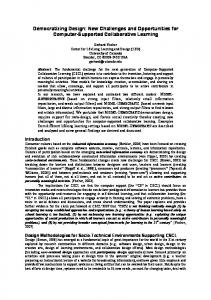
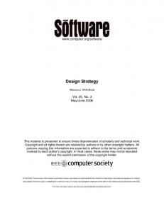
avoidance), and system-wide, global computations (like graceful degradation). Centralizing eases assessment of these safety measures, but for high-reactive parts, the safety block needs to be put local. Maintenance processing elements can also be added here. • Effects due to non-idealness of the computer hardware. Add the control computer hardware non-idealness and software architecture. Effects of latency and jitter can be checked. Scheduling techniques and / or algorithm optimization techniques may be used to optimize the realisation. Enhancements as indicated above concern the software parts, and not so much the control algorithms. Traditional tools for control law design and tuning are not sufficient anymore to include these enhancements. At this point in the method, it makes sense to move the control algorithms to the software development tool. This is illustrated in Fig. 2, where in Step 3a lines b and c are combined. This implies that co-simulation is needed. In this paper we use Overture and 20-sim, and its combined co-simulation with the DESTECS tool. All parts resulting in software go to the discrete part, and the plant dynamics stay in the continuous time part. This is especially relevant for the I/O components, as these are divided over the embedded control and physical parts. In the (co-)simulation models, the division between embedded control part and physical part is indicated by the discretisation blocks, i.e. A/D, D/A converters, Samplers, Zero-Order Holds. It is best to move to a co-simulation after all loop controllers have been tuned. When the model is enhanced enough, the next step (3b) is to check whether the envisaged target embedded computer can run the embedded software with respect to the timing constraints. When computation time can be sufficiently accurately predicted, one can check timing using these predictions. VDM-RT, i.e. VDM with timing information can be used for this. After that, a real-time simulation, or Hardware-in-the-Loop simulation can be performed: the plant is simulated, and the embedded control software runs on the target processor (or a comparable, more powerful variant to allow room for monitoring and debugging). Doing so, the work in step 4 is less. E. Step 4: Realization This Step basically is to exchange the virtual plant with the real plant / hardware. Note that for this action, during Step 3, the I/O must be partitioned such that the modelled hardware part can be decoupled, such that interface at this decoupling is exactly the interface to the real hardware, see Fig. 3. This also implies that in the virtual prototype, the interfaces at the physical hardware side need to be simulated. The dashed line at the lower left part in Fig. 2 represents that the result of a (Electronics design) results in the I/O hardware. The embedded control computer normally is a commercial off-the-shelf component. The dashed line at the lower right part if Fig. 2 represents the result of e) (Mechanics design) being the plant.
342
Embedded Control System Signal conditioning Electrical
Output driver
Controller
interface
Electrical
D/A, encoder, etc.
Sensor simulation
interface
A/D, PWM, etc.
Model of the plant
Actuator simulation
Fig. 5.
Detailed components of the whole system – Step 2
Hardware-In-the-Loop simulator
Fig. 3.
Typical model for use in a HIL setup
Fig. 6.
Fig. 4.
Co-simulation – Step 3
IOInterface block can be detailed out as D/A and A/D converters.
Top-level architecture of the system – Step 1
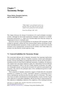
Obviously, when in Step 3b the embedded control software does not yet run on the target processor(s), the software has to be moved there. One can test this first against the virtual prototype. However, when performance test using the more powerful development machine indicate that the final target processor can handle the software, this test can be skipped. When Step 3 has been worked on thoroughly, the total system should work right the first time. IV. C ASE E XAMPLE Based on the approach proposed above, a case example of modelling and implementation of a second order dynamic system is demonstrated here. Although this is a textbook example, it is enough to indicate the approach introduced in this paper. A. Step 1: Global Architecture and Physical System Modelling Following the method of Sec. III, first the overall model structure of the CPS is given in Fig. 4. Having a top-level architecture representing the system helps for each component’s later refinement. The coloured backgroud shades indicate which part is the discrete-event part ultimately implemented on a control computer, the left-hand side, and which part is realized in physics (i.e. electrical, mechanica, pneumatic, hydraulic domains), the right-hand side. This is Step 1 b) in Fig. 2. Step 1 d) is shown in the right-hand side of Fig. 5, namely the bond-graph model. B. Step 2: Control law design As shown in Fig. 5, the Controller block in Fig. 4 can be detailed out as a standard PID controller, implemented as a discrete-time controller. The left-hand side in Fig. 5 represents the design of the control law, which can be done by standard PID controller parameter tuning. The
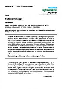
C. Step 3: Embedded Control System implementation After the PID controller tuning in step 2, a co-simulation is needed to verify the design of this step. This is exactly what Step 3 a) illustrated in Fig. 2. Fig. 6 shows the controller stub, now being implemented using VDM. Fig. 7 is an example of a standard PID controller implementation in VDM. D. Step 4: Realisation Step 4 is not shown here, as we focus on modelling and co-simulation to support embedded control software design. It is beneficial to perform in this Step the same experiments as done in the previous Step. This way, one can precisely compare the final results with earlier simulations. When the previous steps have been executed precisely, Step 4 should be a first-time-right realisation of the embedded control software. Experiences by the industrial partners within the DESTECS project showed that the approach presented here is really beneficial as development time shortens, and the better quality (i.e. less errors in the models) is achieved. V. C ONCLUSIONS We conclude that the approach here is beneficial, as it helps structuring models. Parts can be reused elsewhere, as due to the structuring, the chance is higher an existing submodel fits in a new situation. Co-simulation supports the design process, as the software structure being precisely modelled, can be more extensively tested using a virtual plant (we experienced this in our lab: [7]). This, compared to testing embedded control software using stubs for inputs and outputs to the plant. We drew this conclusion from the work among others in the EU FP7 DESTECS project, which supports this research. Future work is to precisely test the method on more complex examples. To avoid IP problems due to confidentiality, we plan to use a somewhat more complex setup in
343
� class Controller instance variables -- shared variables public err: real := 0.0; public out: real := 0.0; -- PIDcontroller private pid: PID; values -- design parameters public kp: real = 3.0; public tauD: real = 0.2; public beta: real = 0.1; public tauI: real = 1.0;
operations -- constructor for controller public Controller: () ==> Controller Controller() == ( pid := new PID(kp,tauI,tauD,beta); pid.SetSampleTime(0.01) ); -- do control step public ControlStep: () ==> () ControlStep() == duration(0) ( out := pid.Output(err); ); thread -- 100Hz periodic(10E6,0,0,0)(ControlStep); end Controller
�
�
Fig. 7.
Controller model in VDM
our lab, namely a mockup of a production cell, consisting of 6 motor (PID) control loops that are synchronised by sequence and supervisory controllers, currently expressed in state machines [17]. Furthermore, we want to extend the presented design method to also cover the electronics and the mechanics part.
[6] J. F. Broenink, P. G. Larsen, M. Verhoef, C. Kleijn, D. S. Jovanovi´c, K. G. Pierce, and F. Wouters, “Design support and tooling for dependable embedded control systems,” in Proceedings of SERENE ’10, ACM. ACM Sigsoft, Apr. 2010, pp. 77 – 82. [7] M. A. Groothuis, A. S. Damstra, and J. F. Broenink, “Virtual prototyping through co-simulation of a cartesian plotter,” in Emerging Technologies and Factory Automation, 2008. ETFA 2008. IEEE International Conference on, no. 08HT8968C. IEEE Industrial Electronics Society, Sept. 2008, pp. 697–700. [8] J. Eker, J. W. Janneck, E. A. Lee, L. Jie, X. Liu, S. Ludvig, S. Neuendorffer, S. Sachs, and Y. Xiong, “Taming heterogeneity— the ptolemy approach,” in Proceedings of the IEEE, vol. 91, no. 1, Jan. 2003, pp. 127 – 144. [9] D. S. Jovanovi´c, “Designing dependable process-oriented software, a csp approach,” PhD thesis, University of Twente, Enschede, The Netherlands, 2006. [10] C. A. R. Hoare, Communicating Sequential Processes. London: Prentice-Hall, 1985. [11] M. ten Berge, B. Orlic, and J. F. Broenink, “Co-simulation of networked embedded control systems, a csp-like process-oriented approach,” in Proceedings of the IEEE Int’l Symposium on Computer Aided Control Systems Conference, CACSD 2006. IEEE Control Systems Society, 2006, pp. 434–439. [Online]. Available: http://doc.utwente.nl/57680/ [12] J. F. Broenink and G. Hilderink, “A structured approach to embedded control systems implementation,” in Proceedings of the 2001 IEEE International Conference on Control Applications, M. W. Spong, D. Repperger, and J. M. I. Zannatha, Eds. IEEE, 2001, pp. 761– 766. [13] J. F. Broenink, M. A. Groothuis, P. Visser, and B. Orlic, “A modeldriven approach to embedded control system implementation,” in Proceedings of the 2007 Western Multiconference on Computer Simulation WMC 2007, San Diego, J. Anderson and R. Huntsinger, Eds. San Diego: SCS, San Diego, January 2007, pp. 137–144. [14] J. F. Broenink, M. A. Groothuis, P. Visser, and M. M. Bezemer, “Model-driven robot-software design using template-based target descriptions,” in ICRA 2010 workshop on Innovative Robot Control Architectures for Demanding (Research) Applications, D. Kubus, K. Nilsson, and R. Johansson, Eds., IEEE. IEEE, May 2010, pp. 73 – 77. [Online]. Available: http://www.rob.cs.tu-bs.de/en/news/icra2010 [15] P. C. Breedveld, Port-Based Modeling of Engineering Systems in Terms of Bond Graphs. London, New York: Chapman & Hall, Boca Raton, 2007, pp. 26.1–26.29. [16] ——, Chapter 1: Port-Based Modeling of Dynamic Systems. Springer Verlag, 2009, pp. 1–52. [17] M. A. Groothuis and J. F. Broenink, “Hw/sw design space exploration on the production cell setup,” in Communicating Process Architectures 2009, Eindhoven, The Netherlands, ser. Concurrent Systems Engineering Series, P. Welch, H. Roebbers, J. F. Broenink, and F. R. M. Barnes, Eds., vol. 67, no. WoTUG-32. Amsterdam: IOS Press, Nov. 2009, pp. 387–402.
ACKNOWLEDGEMENTS The research leading to these results has received funding from the European Community’s Seventh Framework Programme (FP7/2007-2013) under grant agreement no. 248134 (project DESTECS). R EFERENCES [1] B. Selic, “The pragmatics of model-driven development,” IEEE Software, vol. 20, no. 5, pp. 19–25, Sept. 2003. [2] D. C. Karnopp, D. L. Margolis, and R. C. Rosenberg, System Dynamics: modeling and simulation of mechatronic systems. Wiley, 2006. [3] P. C. Breedveld, “Multibond-graph elements in physical systems theory,” Journal of the Franklin Institute, vol. 319, no. 1/2, pp. 1– 36, 1985. [4] C. B. Jones, Systematic Software Development using VDM, 2nd ed. Prentice Hall International, 1990. [Online]. Available: http://homepages.cs.ncl.ac.uk/cliff.jones/ftp-stuff/Jones1990.pdf [5] J. S. Fitzgerald, P. Larsen, P. Mukherjee, P. N., and M. Verhoef, Validated Designs for Object-oriented Systems. Springer, 2005. [Online]. Available: http://www.springerlink.com/content/978-1-85233-881-7
344